EP0641704A2 - Traîneau à une seule roue - Google Patents
Traîneau à une seule roue Download PDFInfo
- Publication number
- EP0641704A2 EP0641704A2 EP94306241A EP94306241A EP0641704A2 EP 0641704 A2 EP0641704 A2 EP 0641704A2 EP 94306241 A EP94306241 A EP 94306241A EP 94306241 A EP94306241 A EP 94306241A EP 0641704 A2 EP0641704 A2 EP 0641704A2
- Authority
- EP
- European Patent Office
- Prior art keywords
- travois
- frame member
- attached
- user
- assembly
- Prior art date
- Legal status (The legal status is an assumption and is not a legal conclusion. Google has not performed a legal analysis and makes no representation as to the accuracy of the status listed.)
- Withdrawn
Links
Images

Classifications
-
- B—PERFORMING OPERATIONS; TRANSPORTING
- B62—LAND VEHICLES FOR TRAVELLING OTHERWISE THAN ON RAILS
- B62B—HAND-PROPELLED VEHICLES, e.g. HAND CARTS OR PERAMBULATORS; SLEDGES
- B62B5/00—Accessories or details specially adapted for hand carts
- B62B5/06—Hand moving equipment, e.g. handle bars
- B62B5/068—Connections to the body for moving the cart, e.g. harnesses
-
- B—PERFORMING OPERATIONS; TRANSPORTING
- B62—LAND VEHICLES FOR TRAVELLING OTHERWISE THAN ON RAILS
- B62D—MOTOR VEHICLES; TRAILERS
- B62D51/00—Motor vehicles characterised by the driver not being seated
- B62D51/04—Motor vehicles characterised by the driver not being seated the driver walking
-
- B—PERFORMING OPERATIONS; TRANSPORTING
- B62—LAND VEHICLES FOR TRAVELLING OTHERWISE THAN ON RAILS
- B62B—HAND-PROPELLED VEHICLES, e.g. HAND CARTS OR PERAMBULATORS; SLEDGES
- B62B5/00—Accessories or details specially adapted for hand carts
- B62B5/04—Braking mechanisms; Locking devices against movement
Definitions
- the present invention relates to a wheeled travois for towing supplies and other loads behind an individual.
- the wheeled travois of the present invention is particularly useful for towing supplies and other loads over uneven terrain.
- the prior art presents a diverse array of embodiments of different devices which may be employed to tow or carry a load behind an individual.
- the object of these devices is to assist an individual in transporting a load, especially those loads weighing more than an individual may comfortably carry for any significant distance.
- many different types of carriers exist including carriers which are handheld and may be either pushed or pulled and carriers which are attached to and towed behind an individual, each of the carriers found in the prior art have at least one of several problems including stability, limitations of maneuverability or desirability of function.
- carriers with a load carrying frame having a single wheel structure which may be attached to and towed behind an individual.
- a common design disclosed by the prior art teaches a travois which is attached to the user at two points, and includes embodiments where the attachment is made to either a belt or an over the shoulder harness worn by the user. While the use of two points of attachment creates a stable arrangement, it imposes as substantial trade-offs unwanted limitations on maneuverability and desirability of use due in part to limitations on side to side movement and additional weight in the frame.
- Embodiments of a travois using two points of attachment may be found in United States Patent No. 2,613,953 to Giovannoni, United States Patent No. 2,655,957 to Lagant, United States Patent No. 4,045,040 to Fails, and United States Patent No. 4,664,395 to McCoy. Of these the Fails embodiment also undesirably uses a two wheel structure.
- a first object of the present invention is to provide a monowheel travois which overcomes some of the shortcomings of the prior art.
- Another object of the present invention is to provide a monowheel travois which employs an abbreviated backpack frame that distributes the load from the load carrying frame to the individual. This has the advantage of providing a less cumbersome more maneuverable assembly with less weight and fewer pieces.
- a further object of the present invention is to provide a monowheel travois which employs an attachment between the backpack and the load carrying frame that will allow the travois to move side to side (yaw) and up and down (pitch) relative to the user without allowing the travois to roll from an upright position.
- This enables the travois to be supported at it's lower end on a wheel made up of a single disk allowing a narrower profile than the prior art arrangements.
- the advantages to this configuration are numerous, including the ability to follow the user down narrow trails, and to squeeze between trees and other obstacles.
- Yet another object of the present invention is to provide a travois which may be quickly released from the user's backpack. This has obvious advantages in an emergency and is useful at any time the user wants to separate from the travois.
- a further object of the present invention is to provide a monowheel travois which employs a load carrying frame configured so that it may be dragged over obstacles too big for the wheel to roll over.
- the advantage to this is that there is virtually no terrain that the travois cannot traverse.
- Another object of the present invention is to provide a monowheel travois which can be carried in a similar manner to a standard backpack without the wheel on the ground.
- the advantage here is that it can be carried over terrain that it cannot roll over.
- Another object of the present invention is to provide a monowheel travois which employs a single braking system that can apply variable braking pressure to the wheel and continuously lock the wheel for steep descents.
- the locking feature is also valuable when the travois is not in use and resting on the ground.
- Yet another object of the present invention is to provide a monowheel travois which employs a load carrying frame configured so that the center of gravity of the load is below the center of gravity of the travois.
- the load must also be placed so that it does not interfere with the users normal stride. This creates a very stable arrangement that is not prone to roll over and is very maneuverable.
- a final object of the present invention is to provide a monowheel travois which employs a wide range of adjustment in length and backpack attachment points. This enables the travois to fit a wide range of user body types comfortably. The Travois should also break down into pieces small enough to fit into a average automobile trunk.
- a travois assembly comprises a load-carrying frame having a lower end and an upper end.
- a single wheel is rotatably mounted on said lower end of said load carrying frame.
- a user harness includes a single vertical frame member attached to a horizontal frame member at a lower end thereof, a back pad attached to the vertical frame member at an upper end thereof, a belt circumferentially attached to the horizontal frame member, a pair of shoulder straps each having a first end attached to the back pad and a second end attached to the horizontal frame member.
- the load carrying frame is attached to the user harness by a universal joint having a first end rigidly attached to the upper end of the load carrying frame and a second end attached to the vertical frame member of the user harness.
- the back pad is vertically adjustable.
- the position where the load carrying frame is connected to the vertical frame member of the user harness is also vertically adjustable.
- a braking system is employed to allow the user of the travois to apply frictional force to oppose the rotation of the wheel. This feature of the invention is useful for applications where descending hills is encountered.
- means are provided for quickly releasing the load carrying frame from the user harness. This feature of the invention is important in an emergency situation, such as a fall by the user of the travois.
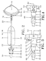
- FIG. 1 is a side view of the travois of the present invention shown elevated as if in use and with the saddlebags removed.
- FIG. 2 is a top view of the travois of the present invention, with the cables, the backpack pad and straps omitted for clarity.
- FIG. 3 is a side view detail of a presently preferred quick release/universal joint assembly of the travois of the present invention.
- FIG. 4 is a top view detail of the quick release/universal joint assembly of FIG. 3.
- a single wheeled travois and backpack apparatus wherein the travois is connected to the backpack at a single point.
- the structure employed at the place of connection provides several unique and desirable features including a quick release mechanism, and a universal joint assembly.
- FIGS. 1 and 2 side and top views of a presently preferred embodiment of the monowheel travois of the present invention are shown.
- a user worn backpack 10 is shown connected by a universal joint assembly 12 to a single wheeled travois 14.
- travois 14 includes a generally triangular shaped load bearing frame 16 which may be formed from a lightweight sturdy material such as aluminum tubing.
- load bearing frame 16 includes a main load bearing frame member 18 including two bends therein to form an upper end 20 and a lower end 22.
- a lower load bearing frame member 24 is bent near its midpoint and has its ends welded near the bends in the main load bearing member 18.
- a brace member 26 is welded between the bend in the lower load bearing frame member 24 and main load bearing frame member 18 to form a support between the main load bearing member 18 and the lower load bearing frame member 24 and strengthen load bearing frame 16.
- load bearing frame 16 While a particular embodiment which has actually been constructed according to the principles of the present invention has been described, those of ordinary skill in the art will recognize that different configurations of load bearing frame 16 are possible. Non-limiting examples include, a single load bearing frame member, a "cage" for the load or a single large diameter cylindrical member with storage space in its interior. Other materials may also be used to fabricate the load bearing frame 16 including thin wall high tensile steel tube or carbon fibre-epoxy composite. Further, the load bearing frame 16 can be collapsible to facilitate storage in an automobile trunk, and the upper end 20 of main bearing frame member 18 can be formed from telescoping sections to allow for adjustment in length to suit individual users.
- the upper end 20 of the main load bearing frame member 16 is bent at an angle behind the universal joint assembly 12 such that it is attached to the universal joint assembly 12 in an approximately horizontal position when in use. This keeps the vertical side of the universal joint horizontal when the user and the travois are in a normal position to each other and allows more freedom of movement on steep slopes.
- a skidplate 26 may be attached to the underside of the lower load bearing frame member 24.
- the skidplate 26 may be formed from a material such as ABS plastic cut to shape and molded to fit the underside of the lower load bearing frame member 24.
- Other embodiments of the skidplate 26 include aluminum sheet or carbon fibre-epoxy composite molded integrally to the lower load bearing frame member 24.
- the skid plate 26 When the user encounters terrain that the wheel is unsuitable for, the skid plate 26, supported by the lower load bearing frame member 24 acts as a sled allowing the user to drag the travois 14 over virtually any terrain.
- the skid plate 26 also protects the load and may also be employed as a stand to keep the travois 14 in an upright position when sitting on the ground or during loading and unloading.
- saddlebag structure 28 may be removable for the convenience of the user and will be fastened to the load-carrying frame by any one of a number of conventional means, such as straps, etc.
- Saddlebags 28 can be any type of convenient arrangement of bags to serve this purpose.
- the current embodiment uses a pair of backpack-bags manufactured by Sierra Designs and modified with a series of grommets (not shown) to enable them to be fixed to the main load bearing frame member 18 with a series of clevis pins (not shown). It would be convenient to make use of a set of custom made saddlebags 28 to approximately conform to the shape of the load bearing frame 16.
- Several arrangements of straps (not shown) attached to the skid plate 26, the saddlebags 28 and/or the load bearing frame 16 may be used to further affix the load to the load bearing frame 16.
- One of ordinary skill in the art will recognize that many different types of load carrying bags and devices can be used to affix the load to the load bearing frame 16.
- a steel wheel fork 30 comprising a shaft 32 and a fork 34 is attached to the lower end 22 of the load bearing frame 16. This may be accomplished by, for example, fitting and pinning the lower end 22 of the load bearing frame 16 within a sleeve in the wheelshaft 32.
- a wheel assembly 36 is mounted on axle 38, which is mounted to fork 34 in a conventional manner.
- wheel assembly 36 comprising a ten inch injection molded wheel 38 and a radially mounted inflatable inner tube and rubber tire assembly 40.
- Posts 42 are attached to the fork 34 to form the attachment for a brake assembly 44 which in the preferred embodiment is a cantilever type.
- backpack 10 includes a harness and a external backpack frame.
- the harness comprises a pair of shoulder straps 46 and a waist belt 48.
- the external backpack frame comprises a horizontal backpack frame member 50, a vertical backpack frame member 52, and a backpad 54.
- the waist belt 48 and the lower ends of shoulder straps 46 are attached with a nut and bolt or clevis pin to the outer ends of the horizontal backpack frame member 50.
- the horizontal backpack frame member 50 is shown attached at its midpoint to the lower end of the vertical backpack frame member 52.
- An integrated assembly including backpad 54 and first adjustable clamp 56 is mounted on the upper end of vertical backpack frame member 52 using a first locking screw 58.
- the upper ends of shoulder straps 46 are then fastened to the first adjustable clamp 56 on the sides of the backpad 54.
- the horizontal backpack frame member 50 is radially curved to generally fit the curvature of a users back. This feature enhances the stability of the travois 14 and provides greater comfort to the user of the backpack 10.
- the integrated backpad 54 and first adjustable clamp 56 are adjustable to different heights relative to the horizontal backpad frame member 50 by loosening the first locking screw 58 and then sliding the integrated backpad 54 and first adjustable clamp 56 to a position in either direction along the vertical backpad frame member 52 and then tightening the first locking screw 58.
- Those of ordinary skill in the art will recognize that a variety of mechanisms may be employed to fasten and unfasten the first adjustable clamp 56.
- the adjustability of the backpad 54 and upper shoulder strap 46 to accommodate the height of a particular user greatly enhances comfort and stability.
- the backpack frame may be formed from tubular aluminum stock.
- the horizontal and vertical backpack frame members 50 and 52, respectively, are preferably welded at their juncture, although other known fastening means may be employed.
- Other embodiments of the backpack frame could make use of materials such as thin wall high tensile steel tubing, carbon fibre-epoxy composite construction, injection molded plastics, or a combination thereof.
- the backpad 54 may comprise foam covered ABS plastic shaped to fit the human back and encased in nylon mesh (not shown), and the integral first adjustable clamp 56 may comprise aluminum.
- Other embodiments of the integrated backpad 54 and first adjustable 56 may also include many types of injection molded plastics having both components molded as one piece.
- the quick release mechanism 60 includes a second adjustable clamp 62 including a female release member 64 into which fits a male release member 66 connected to universal joint assembly 12.
- a female release member 64 into which fits a male release member 66 connected to universal joint assembly 12.
- the present embodiment shows the male release member 66 of second adjustable clamp 62 connected to the universal joint assembly 12 and the female release member connected to the backpack frame 10, those of ordinary skill in the art will recognize that this arrangement could be reversed.
- the second adjustable clamp 62 is mounted on the vertical backpack frame member 52 and fastened to the vertical backpack frame member 52 by a locking screw 68.
- second adjustable clamp 62 is adjustable to different heights relative to the horizontal backpad frame member 50 by loosening the second locking screw 68 and then sliding the second adjustable clamp 62 to a selected position in either direction along the vertical backpad frame member 52 and then tightening the second locking screw 68.
- Those of ordinary skill in the art will recognize that a variety of mechanisms may be employed to fasten and unfasten the second adjustable clamp 62. This allows the load point to be configured for any given users height or personal preferences.
- Those of ordinary skill in the art will recognize that a variety of mechanisms may be employed to fasten and unfasten the second adjustable clamp 62. It is not necessary, however, that the mechanism employed to fasten and unfasten both the first adjustable clamp 56 and the second adjustable clamp 62 be the same.
- both the second adjustable clamp 62 and the male release member 66 of the universal joint assembly 12 are of milled aluminum.
- Other embodiments could make use of steel, carbon fibre-epoxy composite or injection molded plastic for these elements.
- the female release member 64 of the quick release mechanism 60 comprises an aperture 70 disposed in a sidewall of the second adjustable clamp 62, and a first quick release pinhole 72 passing vertically through the top of the second adjustable clamp 62 into the aperture 70.
- the aperture 70 is roughly rectangular in shape having inside corners that are rounded and a lip 74 at the base of the aperture 70.
- the male release member 66 of the universal joint assembly 12 is also roughly rectangular in shape having corners rounded to mate with the aperture 70, a groove 76 shaped to mate with the lip 74 of aperture 70, and a second quick release pinhole 78.
- the first quick release pinhole 72 and the second quick release pinhole 78 are formed such that when male release member 66 is mated with female release member 64, the first and second quick release pinholes 72 and 78 will be in alignment with one another.
- the quick release mechanism 60 is engaged by positioning the groove 76 over the lip 74, mating the male release member 66 with the female release member 64, and then inserting a quick release pin 80 through the first quick release pinhole 72 into the second quick release pinhole 78.
- female release member 64 could be spring loaded to actively eject a male release member 66 when quick release pin 80 is pulled.
- the configuration could also be altered to incorporate a ski-binding type release that will release the male member 66 when a preset maximum load setting has been reached.
- universal joint assembly 12 comprises an automotive universal joint from a domestic power steering system.
- a first end 82 of universal joint assembly 12 is attached to male release member 66, and a second end 84 of universal joint 12 is attached to upper end 20 of load bearing frame 16 (FIGS. 1 and 2).
- the first end 82 of universal joint assembly 12 is attached to male release member 66 by pinning it within a sleeve in male release member 66.
- the second end of universal joint assembly 12 is attached to upper end 20 of load bearing frame 16 by pinning upper end 20 of load bearing frame 16 within a sleeve in second end 84 of universal joint assembly 12.
- the universal joint assembly 12 enables the travois to be trailed on one wheel without sacrificing stability and further keeps the load and travois vertically positioned at all times no matter what the cross slope or terrain the user is walking across.
- FIG. 3 it may be seen that as the travois 14 starts to align vertically with the user's back, the first pair of universal joint arms 86 progressively engage the second pair of universal joint arms 88. At its extreme limit of travel this will lock the first pair of universal joint arms 86 between the second pair of universal joint arms 88 preventing rollover of the travois 14 on steep slopes. Referring to FIG.
- a third adjustable clamp 90 may be attached to the lower load bearing frame member 24 by a locking screw 92.
- Third adjustable clamp 90 is equipped with a male release member 94 shaped like the male release member 66 of quick release mechanism 60 and may be engaged within the female release member 64 of the quick release mechanism 60 in the same manner as male release member 66.
- the third adjustable clamp 90 may be positioned along the lower load bearing frame member 24 in the same manner recited for positioning the first and second adjustable clamps 56 and 62 along the vertical backpack frame member 52.
- lower load bearing frame member 24 is configured to keep the load from rotating about the frame and to keep the center of gravity of the load below the center of gravity of the travois 14.
- the lower load bearing frame member 24 also has a geometry that provides room for the user with a normal stride in front of and underneath the load bearing frame 16.
- the profile of the travois 14 is very narrow, and the ability to tow the travois 14 in narrow, confined or rough places is enhanced. All of these features work together to provide a travois 14 with increased comfort, maneuverability and function.
- the travois 14 user has an unprecedented freedom of movement while towing a load with the travois 14.
- a first cable 96 is shown attached at one end with a cable clamp (not shown) to a first ring 98 on quick release pin 80.
- a second ring 100 is attached with a cable clamp (not shown) to the other end of the first cable 96.
- First cable 96 may be draped over the shoulder of a user to be readily available or may be passed through a loop (not shown) fastened to shoulder straps 46 by a variety of means known in the art.
- First cable 96 is employed to operate the quick release mechanism 60.
- the quick release pin 80 By pulling on the second ring 100, the quick release pin 80 may be withdrawn from the first quick release pinhole 72 and the second quick release pinhole 78, disengaging the quick release mechanism 60.
- the weight of the travois 14, rotating on the universal joint assembly 12, will disengage the quick release mechanism 60, allowing the user to quickly detach the backpack 10 from the travois 14 while underway if necessary. This is an important safety feature.
- the quick release mechanism 60 is also an important convenience feature by making the travois 14 easy to disengage to be picked up and carried, drug, or reattached to the backpack 10 by the male release member 90 on load bearing member 24 so that it may be carried on the backpack 10.
- a second cable 102 is shown attached at one end to the brake assembly 44 and at the other end to a brake handle assembly 104 comprising a handle 106 and a brake lever 108.
- Second cable 102 may also be draped over the shoulder of a user to be readily available or may be passed through a loop (not shown) fastened to shoulder straps 46 by a variety of means known in the art.
- the braking system composed of brake assembly 44, second cable 102 and brake handle assembly 104 act as a normal bicycle brake on the wheel.
- the wheel could be replaced by a single ski, thus allowing the travois of the present invention to be used in the snow.
- the backpack could be eliminated and the second adjustable clamp 62 could be attached to a single point on a bicycle frame member, allowing the travois of the present invention to be towed behind a bicycle.
Applications Claiming Priority (2)
| Application Number | Priority Date | Filing Date | Title |
|---|---|---|---|
| US08/117,953 US5385355A (en) | 1993-09-07 | 1993-09-07 | Monowheel travois |
| US117953 | 1993-09-07 |
Publications (2)
| Publication Number | Publication Date |
|---|---|
| EP0641704A2 true EP0641704A2 (fr) | 1995-03-08 |
| EP0641704A3 EP0641704A3 (fr) | 1995-08-09 |
Family
ID=22375723
Family Applications (1)
| Application Number | Title | Priority Date | Filing Date |
|---|---|---|---|
| EP94306241A Withdrawn EP0641704A3 (fr) | 1993-09-07 | 1994-08-24 | Traîneau à une seule roue. |
Country Status (3)
| Country | Link |
|---|---|
| US (1) | US5385355A (fr) |
| EP (1) | EP0641704A3 (fr) |
| CA (1) | CA2131484C (fr) |
Cited By (1)
| Publication number | Priority date | Publication date | Assignee | Title |
|---|---|---|---|---|
| US20130192410A1 (en) * | 2010-10-05 | 2013-08-01 | Johria Innovation Ab | Safety arrangement |
Families Citing this family (39)
| Publication number | Priority date | Publication date | Assignee | Title |
|---|---|---|---|---|
| US5511802A (en) * | 1994-12-13 | 1996-04-30 | Warwick Aitken | Single wheel baby stroller |
| US5580069A (en) * | 1995-06-12 | 1996-12-03 | Trejo; Luis | Runner to bicycle connecting device |
| US5769431A (en) * | 1995-11-06 | 1998-06-23 | Cordova; Paul | Backpack and load conveyance apparatus |
| US5901968A (en) * | 1997-02-20 | 1999-05-11 | Niedersteiner; Anton M. | Pedestrian trailer system |
| US5842707A (en) * | 1997-08-19 | 1998-12-01 | Smith; Jeffrey Hayes | Single wheel zero turn riding sulky for use with a self-propelled vehicle |
| US6039333A (en) * | 1998-02-09 | 2000-03-21 | Hamblin; Steven Lee | Hiker's utility trail cart |
| US6139033A (en) * | 1998-11-20 | 2000-10-31 | Western; David Owen | Stable monowheel travois with counterweight feature |
| US6361063B1 (en) * | 1999-03-18 | 2002-03-26 | Douglas Lincoln Daeschner | Portage device |
| FR2817717B1 (fr) * | 2000-12-07 | 2003-08-15 | Michel Besancon | Dispositif d'aide au portage et a la traction des charges dorsales et des skis |
| US6685198B1 (en) * | 2002-03-18 | 2004-02-03 | Donald Dewayne Hartman | Cart |
| US6631777B1 (en) * | 2002-06-17 | 2003-10-14 | Allister Wade Thompson | Transport vehicle for skaters and skiers |
| US20040150175A1 (en) * | 2003-02-03 | 2004-08-05 | Cepull George F. | Travois apparatus and method |
| US6935643B1 (en) * | 2003-05-20 | 2005-08-30 | Donald V. Purpuro | Hiker's trail carrier |
| US7678026B2 (en) * | 2004-05-21 | 2010-03-16 | Robert Lewis | Mobile physical training system and method thereof |
| US20060079573A1 (en) * | 2004-10-10 | 2006-04-13 | Jakob Vinten-Johansen | Methods and compositions for preventing vasospasm |
| US7311313B1 (en) | 2004-11-04 | 2007-12-25 | Sarah Joan Ray | Hands-free jogging stroller adaptor with shock absorber |
| US20060108756A1 (en) * | 2004-11-24 | 2006-05-25 | Kerr Ben F | Hands-free vehicle control device |
| US7484737B2 (en) * | 2005-04-16 | 2009-02-03 | Dale Jeffrey Satorius | Towable pack carrier |
| US7195248B1 (en) * | 2005-04-26 | 2007-03-27 | Miesch Gregg B | Wheelbarrow attachment for the back of the bucket of a wheelbarrow |
| US7600764B1 (en) | 2005-07-27 | 2009-10-13 | George Parker | Pedestrian trailer |
| US7322584B1 (en) | 2005-07-27 | 2008-01-29 | Parker George C | Pedestrian trailer |
| US20070075105A1 (en) * | 2005-10-04 | 2007-04-05 | Petrin Raymond R | Trailable backpack |
| US20070187910A1 (en) * | 2006-02-15 | 2007-08-16 | Jacqueline Adams | Pusher for stroller |
| US7549648B2 (en) * | 2006-06-05 | 2009-06-23 | Daniel Girard | Human-powered, hands-free, maneuverable, multi-use trailer |
| US20080238024A1 (en) * | 2007-03-27 | 2008-10-02 | Gerald Heidenreich | Hands Free Baby Stroller Attachment |
| US20090243242A1 (en) * | 2008-03-26 | 2009-10-01 | Bruce Houston | Wheelbarrow Propulsion Device and Methods of Use |
| US8708206B2 (en) * | 2008-08-29 | 2014-04-29 | Shawn Onessimo | Bag that distributes weight over the back of a person |
| EP2501257B1 (fr) * | 2009-11-19 | 2015-01-21 | Tal & Hadas Ltd. | Système et procédé pour porter des charges |
| US8893937B1 (en) | 2011-06-28 | 2014-11-25 | Jared D. Bristol | Multiple mode portable wheeled backpack |
| WO2014172217A1 (fr) * | 2013-04-14 | 2014-10-23 | Eric Hjertberg | Remorque personnelle utilisant une seule roue sphérique |
| US9969412B2 (en) | 2013-07-13 | 2018-05-15 | Mcclellan Butte, Llc | Expedition carts and associated methods |
| US9409584B2 (en) | 2013-07-13 | 2016-08-09 | Thomas Joseph Jackson, JR. | Expedition carts and associated systems and methods |
| US9840266B2 (en) * | 2013-10-09 | 2017-12-12 | Glidemachines Llc | Apparatus and method for towing a load by a person |
| US9186538B1 (en) * | 2014-05-22 | 2015-11-17 | Grizzly Performance, LLC | Exercise sled and backpack combination |
| US10112638B2 (en) * | 2015-02-09 | 2018-10-30 | Kendall A. MORSE | Self-adjusting balanced multi-purpose transport carrier |
| US10569818B2 (en) | 2016-03-09 | 2020-02-25 | Joshua Dewain Rogers | Single wheeled transporter |
| US10085536B1 (en) * | 2016-10-25 | 2018-10-02 | David Costigan | Backpack support device |
| WO2020118230A2 (fr) * | 2018-12-06 | 2020-06-11 | Kelling Jeffery | Ensemble sac de roues séparable |
| CN113187794B (zh) * | 2021-04-19 | 2023-06-02 | 北京机械设备研究所 | 一种快速脱插卡扣机构及包括其的单兵负载牵引车 |
Citations (4)
| Publication number | Priority date | Publication date | Assignee | Title |
|---|---|---|---|---|
| US4664395A (en) * | 1985-10-03 | 1987-05-12 | Mccoy Melvin | Multi-purpose uniaxial litter enginery or M.U.L.E. |
| US5005844A (en) * | 1987-12-08 | 1991-04-09 | Douglas & Douglas, Inc. | Travois with roller assembly |
| US5106108A (en) * | 1988-09-19 | 1992-04-21 | Howell Patrick L | Child's sulky and attachment to a human |
| US5265891A (en) * | 1993-01-26 | 1993-11-30 | Diehl Stuart L | Jogger's baby carriage apparatus |
Family Cites Families (2)
| Publication number | Priority date | Publication date | Assignee | Title |
|---|---|---|---|---|
| US4045040A (en) * | 1976-01-13 | 1977-08-30 | Fails Hershell W | Deer stand and game carrier |
| US5215355A (en) * | 1992-10-01 | 1993-06-01 | Joe Klumpjan | Hands-free dumping wagon |
-
1993
- 1993-09-07 US US08/117,953 patent/US5385355A/en not_active Expired - Lifetime
-
1994
- 1994-08-24 EP EP94306241A patent/EP0641704A3/fr not_active Withdrawn
- 1994-09-06 CA CA002131484A patent/CA2131484C/fr not_active Expired - Fee Related
Patent Citations (4)
| Publication number | Priority date | Publication date | Assignee | Title |
|---|---|---|---|---|
| US4664395A (en) * | 1985-10-03 | 1987-05-12 | Mccoy Melvin | Multi-purpose uniaxial litter enginery or M.U.L.E. |
| US5005844A (en) * | 1987-12-08 | 1991-04-09 | Douglas & Douglas, Inc. | Travois with roller assembly |
| US5106108A (en) * | 1988-09-19 | 1992-04-21 | Howell Patrick L | Child's sulky and attachment to a human |
| US5265891A (en) * | 1993-01-26 | 1993-11-30 | Diehl Stuart L | Jogger's baby carriage apparatus |
Cited By (1)
| Publication number | Priority date | Publication date | Assignee | Title |
|---|---|---|---|---|
| US20130192410A1 (en) * | 2010-10-05 | 2013-08-01 | Johria Innovation Ab | Safety arrangement |
Also Published As
| Publication number | Publication date |
|---|---|
| US5385355A (en) | 1995-01-31 |
| CA2131484C (fr) | 1998-11-17 |
| CA2131484A1 (fr) | 1995-03-08 |
| EP0641704A3 (fr) | 1995-08-09 |
Similar Documents
| Publication | Publication Date | Title |
|---|---|---|
| US5385355A (en) | Monowheel travois | |
| US6039333A (en) | Hiker's utility trail cart | |
| US7484737B2 (en) | Towable pack carrier | |
| US6139033A (en) | Stable monowheel travois with counterweight feature | |
| EP1188637B1 (fr) | Chariot portable polyvalent | |
| US8091908B2 (en) | Bicycle trailer hitch | |
| US5884920A (en) | Infant carrier for rough terrain | |
| US3887208A (en) | Collapsible and portable utility cart | |
| EP3583014B1 (fr) | Chariot convertible "pression-traction" | |
| US7600764B1 (en) | Pedestrian trailer | |
| US6991243B2 (en) | Platform scooter for larger children and handicapped persons | |
| US20080174078A1 (en) | Pendent load-bearing device | |
| US20100270764A1 (en) | Adaptable Rugged Terrain Cart | |
| WO2002022070A2 (fr) | Déambulateur à roues | |
| US20200369307A1 (en) | Wheeled Pulk and Associated Systems | |
| US20040150175A1 (en) | Travois apparatus and method | |
| CA3122409A1 (fr) | Ensemble sac de roues separable | |
| US5624128A (en) | Transport system for disabled people | |
| US5779248A (en) | Wheeled child carrier | |
| US10882545B2 (en) | Hub and associated method | |
| US20010038190A1 (en) | Bicycle accessory | |
| US20130307231A1 (en) | Portable sled and litter, and methods of assembling same | |
| EP1018462A1 (fr) | Porte-bébé tout terrain | |
| CA2938328C (fr) | Chariots d'expedition et methodes asociees | |
| GB2110924A (en) | Invalid's seat |
Legal Events
| Date | Code | Title | Description |
|---|---|---|---|
| PUAI | Public reference made under article 153(3) epc to a published international application that has entered the european phase |
Free format text: ORIGINAL CODE: 0009012 |
|
| AK | Designated contracting states |
Kind code of ref document: A2 Designated state(s): AT CH DE FR GB IT LI SE |
|
| PUAL | Search report despatched |
Free format text: ORIGINAL CODE: 0009013 |
|
| AK | Designated contracting states |
Kind code of ref document: A3 Designated state(s): AT CH DE FR GB IT LI SE |
|
| STAA | Information on the status of an ep patent application or granted ep patent |
Free format text: STATUS: THE APPLICATION IS DEEMED TO BE WITHDRAWN |
|
| 18D | Application deemed to be withdrawn |
Effective date: 19960210 |