EP0641700B1 - Proportional control of a permanent magnet brake - Google Patents
Proportional control of a permanent magnet brake Download PDFInfo
- Publication number
- EP0641700B1 EP0641700B1 EP19940306588 EP94306588A EP0641700B1 EP 0641700 B1 EP0641700 B1 EP 0641700B1 EP 19940306588 EP19940306588 EP 19940306588 EP 94306588 A EP94306588 A EP 94306588A EP 0641700 B1 EP0641700 B1 EP 0641700B1
- Authority
- EP
- European Patent Office
- Prior art keywords
- electromagnet
- pulses
- braking
- brake
- current
- Prior art date
- Legal status (The legal status is an assumption and is not a legal conclusion. Google has not performed a legal analysis and makes no representation as to the accuracy of the status listed.)
- Expired - Lifetime
Links
Images




Classifications
-
- B—PERFORMING OPERATIONS; TRANSPORTING
- B60—VEHICLES IN GENERAL
- B60T—VEHICLE BRAKE CONTROL SYSTEMS OR PARTS THEREOF; BRAKE CONTROL SYSTEMS OR PARTS THEREOF, IN GENERAL; ARRANGEMENT OF BRAKING ELEMENTS ON VEHICLES IN GENERAL; PORTABLE DEVICES FOR PREVENTING UNWANTED MOVEMENT OF VEHICLES; VEHICLE MODIFICATIONS TO FACILITATE COOLING OF BRAKES
- B60T13/00—Transmitting braking action from initiating means to ultimate brake actuator with power assistance or drive; Brake systems incorporating such transmitting means, e.g. air-pressure brake systems
- B60T13/74—Transmitting braking action from initiating means to ultimate brake actuator with power assistance or drive; Brake systems incorporating such transmitting means, e.g. air-pressure brake systems with electrical assistance or drive
Definitions
- This invention relates to a brake control apparatus and particularly to a proportional control circuit for a permanent magnet brake of the type wherein a permanent magnet creates a magnetic flux path for applying braking force and an electromagnet provides a continuously variable magnetic flux in opposition to the permanent magnet.
- This invention has particular application to wheeled vehicles such as materials handling vehicles.
- a materials handling vehicle a turret stockpicker, includes brakes on the pair of load wheels which are adjusted to have one level of braking force, while brakes on the pair of steered wheels are adjusted to have a second, usually lower, level of braking force. Either pair of brakes may be applied individually or all together to provide three different levels of braking according to the vehicle speed.
- EP-A-0 412 786 discloses a vehicle brake controller including a variable pulse-width modulator operating at a constant frequency and with a variable pulse width to provide control pulses to a MOSFET element which actuates vehicle brakes.
- the controller further includes a visual indicator which displays different colours to representatively indicate the amount of current applied to the brakes, and also to indicate whether an operable connection exists between the electronic controller and the vehicle brakes.
- Proportional control of braking force for spring actuated brakes is difficult because of the variable gap between the brake armature and the solenoid or electromagnetic coil acting on the armature, and also the variable forces applied by the spring to the armature. It would be desirable, however, to provide a proportional control of braking force on a material handling vehicle.
- This invention relates to an electric brake control apparatus providing proportional control over braking force.
- this invention may be used with brakes that are applied by means of a permanent magnet and which are released by application of electrical current to an electromagnetic coil which modifies the intensity of the magnetic flux applied to a brake armature.
- Such a brake is fail safe in that, upon the loss of electric current, the brake will be fully applied through the action of the permanent magnet.
- this brake is fail safe.
- One such brake that might be used in connection with certain material handling vehicles is shown in US Patent No 3 899 061.
- This brake includes a permanent magnet for applying braking force and an electromagnet in the flux path to disengage the brake. Since temperature affects the resistance of the electromagnet, this patent also shows a compensating circuit so that control of the brake is properly maintained.
- the present invention consists in a brake control apparatus for controlling the application of braking torque to a permanent magnet brake of the type having a permanent magnet to create a magnetic flux path for applying a maximum braking torque and an electromagnet to provide a magnetic flux path in opposition to the permanent magnet to release completely said braking torque, the improvement being characterized by means for generating a braking command signal which varies continuously in relation to the amount of braking desired from zero braking to maximum braking, circuit means responsive to said braking command signal for controlling the width and/or frequency of pulses applied to said electromagnet whereby the braking torque may be controlled in direct proportion to the amount of braking torque desired, said circuit means including means for applying pulses of current to said electromagnet, means for applying a first predetermined width and/or frequency of pulses to said electromagnet when no braking torque is desired, which first predetermined width and/or frequency of pulses causes the magnetic flux produced by said permanent magnet to be counteracted by a magnetic flux of opposite polarity from said electromagnet, and means for modifying the
- current to the electromagnetic coil is pulsed at a variable frequency and/or pulse width in response to a brake control signal, which is typically generated according to the position of a brake pedal or a hand grip.
- the brake control signal is applied to a control circuit which controls the pulses applied to the electromagnet to provide a proportional control over braking force.
- the current during each pulse may provide information as to the temperature of the coil of the electromagnet, and in response thereto, appropriate compensation is made. Should the control circuit fail to operate properly, the brake would be fully applied, thus failing safe. Also, the control circuit may be responsive to other vehicle control functions, or an emergency power disconnect, to apply the brakes fully.
- the control circuit may monitor the speed of the wheel with which the brake is associated and an anti-skid algorithm is included in the control circuit to prevent the braking from locking up.
- a typical materials handling vehicle 10 is shown with its access cover removed.
- the vehicle may be of any type but might be a rider reach truck, such as a Series RR or RD truck or a stockpicker, such as a model SP36 truck, both manufactured by Crown Equipment Company.
- the truck shown in Fig. 1 includes a single steerable wheel 15, which is powered by a drive motor 20, stopped by a brake 25, and electrically steered by means of a steering motor 30.
- the drive motor is connected to the axle of the wheel 15 though a gear reduction mechanism 35. Also shown in Fig.
- a pair of motor driven hydraulic motors 40 for providing hydraulic fluid to power other vehicle devices, such as the fork lifting mechanism.
- An emergency disconnect switch 45 is provided within ready access by the operator for the purpose of removing battery power to all vehicle systems.
- the vehicle control electronic circuits including a brake control circuit 50.
- the size of the brake 25 may be reduced considerably over that required of a brake that is connected directly to the wheel of the vehicle.
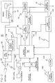
- FIG. 2 is an electrical block diagram of the control circuit 50, one side of an electromagnetic coil 55 of brake 25 is shown connected through a fail-safe device 60 to the vehicle's battery through terminal 65 and emergency disconnect switch 45, and the other side of the coil is connected to ground through a pulse applying circuit 70 and shunt resistor 75 the electromagnetic coil 55 creates a magnetic field in opposition to the field created by a permanent magnet 57.
- the pulsing applying circuit 70 is a typical power control device, such as a MOSFET, capable of handling one to ten amperes.
- the pulsing circuit 70 is driven by a pre-driver circuit 80 which in turn receives a pulse command signal on line 85 from microprocessor 90 which controls the frequency and duration of each pulse.
- the pulse command signal is typically a 5 volt pulse while the output of the pre-driver circuit 80 is 12 volts or higher.
- Pulse monitor circuit 100 is a device that detects the presence of pulses as they are applied to the electromagnet 55. The output of the pulse monitor circuit is applied to the microprocessor 90 as an indication that a continuous stream of pulses, regardless of width, is being applied to the brake. If the stream of pulses fails for any reason, either because the current to the brake is continuous or has fallen to zero, the microprocessor with provide an output to the fail-safe circuit 60 which will remove power entirely from the electromagnet, thus causing brake torque to be applied fully.
- the temperature compensation circuit 105 responds to a signal on line 110 from the microprocessor 90 to monitor the actual current being applied to the coil 55. As shown in Fig. 3, each pulse 120 has a minimum pulse width 125. As current is applied to the coil 55, current initially rises slowly due to the inductive reactance of the coil, but eventually reaches substantially its full current level at 130, at which time the microprocessor generates the signal on line 110 to cause a sample of the current level then flowing to the coil to be taken. This sample current level is converted to digital form and sent to the microprocessor 90 on line 135.
- the actual current flowing to the coil during the sample interval is a function of battery voltage and the resistance of the coil, which is affected by temperature.
- the microprocessor 90 uses either a look up table or a formula to adjust the characteristics of the pulse 120 to compensate for changes in resistance of the electromagnet due to temperature, thus providing for proportional control of braking regardless of temperature.
- the fail-safe circuit 60 may be either a relay or a P-channel MOSFET, Its purpose is either to allow full flow of current to the brake electromagnet or to cut off current flow entirely, either under the direction of the microprocessor 90 or in response to an external control signal on line 140 from a so-called Rip Cord or auxiliary control line designed to intervene directly in the full application of the brake, outside the operation of the microprocessor or any network input from the vehicle control systems to the microprocessor through a network interface 145.
- a signal on Rip Cord line 140 will be acted upon immediately, in real time, causing the brakes to be applied fully, and will not be delayed by the network 145 or action of the microprocessor 90.
- the Rip Cord signal may be initiated by a watch dog program in the vehicle's control system that is monitoring the proper operation of the microprocessor 90, and upon the detection of any failure, it will cause a signal to appear on line 140 to apply the brakes in the fail safe mode.
- a brake pedal or hand grip 150 provides means for generating a braking command signal in response to the amount of braking force desired, from 0% to 100% of the braking force available from the brake 25.
- the braking command signal is either a digital or analog signal, and it passes through filter 155 to the microprocessor 90.
- a tachometer 160 is associated with the wheel 15, the motor 20 or the brake 25 to provide information on the direction of travel, speed and acceleration of the wheel under all operating conditions.
- the output of the tachometer is a digital signal, which also include direction of rotation information, is applied through filter 165 to the microprocessor 90.
- a power supply regulator circuit 170 Also shown in Fig. 2 is a power supply regulator circuit 170. A digital representation of the power supply voltage on line 175 is also applied as an input to the microprocessor 90. The power supply output is provided to the other circuits within Fig. 2 as well as other associated circuits within the vehicle.
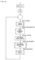
- Figs. 4-7 the brake control system is primarily microprocessor controlled.
- a POR or Power On Reset routine is employed, then the status of all components are checked for proper operation, that is, the input levels are checked to insure they are within acceptable ranges.
- Fig. 5 is a flow chart showing the Read Status routine which checks the various operating conditions of the vehicle, including fork height, travel direction, steering angle, weight on the forks, and the need for a rip cord command.
- the requested braking command from the operator controlled brake pedal or hand grip, is then compared with the actual acceleration, as monitored by reference to the wheel tachometer, and as a result, the appropriate width of the pulse applied to the brake electromagnet is generated, as shown in the flow chart of Fig. 6.
- Fig. 6 also contains the anti skid routine whereby the pulse width is modified to release brake torque whenever the wheel is observed as beginning to lockup.
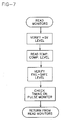
- the Read Monitor routine shown in the flow chart of Fig. 7, verifies the proper operation of the power supply, compensates for variations in temperature, verifies fail safe levels, and insures proper timing of the pulses applied to the electromagnet.
- the microprocessor Upon receipt of a braking command signal, the microprocessor generates pulses that are sent on line 85 to the predriver circuit 80 and then to the pulsing circuit 70 to modify the magnetic force already generated by the permanent magnet within the brake itself.
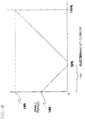
- the pulse width is varied from a minimum width, for maximum braking to a maximum pulse width representing no braking. For example, with a 24 volt, 24 watt electromagnet in the brake, the brake would be fully released at 30% of the rated current of the electromagnet, as shown in Fig. 8. At 0% current, the brake torque 180 would be entirely applied by the permanent magnet. At 100% current, brake torque 185 would be at its maximum.
- the braking force generated in zone 190 from 0 to 30% of electromagnet current, which results from the permanent magnet alone, is sufficient to meet industry standards. Since it is desired that the brake be fail safe, removal of all current from the electromagnet should provide maximum desired or necessary braking force. Of course, if greater torque is desired, the electromagnet could be energized to its higher levels, and the invention described herein could be employed in that mode of operation as well.
- the pulse monitor 100 and temperature compensating circuit 105 are being monitored to insure that the system is operating properly and that the amount of current to the coil is being adjusted for changes in resistance due to temperature.
- the present invention provides for a fail safe, proportional control over a permanent magnet brake of the type where the permanent magnet provides the braking force and where an electromagnet modifies that braking force.
- Full braking torque is applied by a number of systems including the brake command signal in response to the operator depressing a brake pedal, the activation of an emergency stop or disconnect button, which removes all power to the brake coil, a rip cord signal which bypasses the microprocessor and communications network, the microprocessor upon detection of a fault in any of the internal systems or upon failure to detect the regular application of pulses to the brake coil.
- An anti skid algorithm monitors the acceleration of the braked wheel and prevents wheel lockup.
Landscapes
- Engineering & Computer Science (AREA)
- Transportation (AREA)
- Mechanical Engineering (AREA)
- Regulating Braking Force (AREA)
- Braking Systems And Boosters (AREA)
Description
Claims (12)
- A brake control apparatus for controlling the application of braking torque to a permanent magnet brake of the type having a permanent magnet (57) to create a magnetic flux path for applying a maximum braking torque and an electromagnet (55) to provide a magnetic flux path in opposition to the permanent magnet (57) to release completely said braking torque, the improvement being characterized by:-means (150) for generating a braking command signal which varies continuously in relation to the amount of braking desired from zero braking to maximum braking,circuit means responsive to said braking command signal for controlling the width and/or frequency of pulses applied to said electromagnet (55) whereby the braking torque may be controlled in direct proportion to the amount of braking torque desired, said circuit means including:-means (70) for applying pulses of current to said electromagnet (55),means (80,90) for applying a first predetermined width and/or frequency of pulses to said electromagnet (55) when no braking torque is desired, which first predetermined width and/or frequency of pulses causes the magnetic flux produced by said permanent magnet (57) to be counteracted by a magnetic flux of opposite polarity from said electromagnet (55), andmeans (90) for modifying the width and/or frequency of pulses applied to said electromagnet (55) by a continuously variable amount thereby to change the effective magnetic flux generated by said electromagnet (55) as said braking command signal increases from zero braking until maximum braking torque is obtained,means (100) for sensing the presence of said pulses of current to said electromagnet (55), andmeans (60,90) responsive to said sensing means (100) for removing all current to said electromagnet (55) upon the failure of said sensing means (100) to detect the presence of said pulses of current.
- An apparatus as claimed in claim 1, wherein said modifying means (90) includes means for increasing the width and/or frequency of pulses applied to said electromagnet (55) to increase the magnetic flux of a polarity opposite that of said permanent magnet (57) as said braking command signal increases from zero to maximum braking.
- An apparatus as claimed in claim 1, wherein said modifying means (90) includes means for decreasing the width and/or frequency of pulses applied to said electromagnet (55) to decrease the magnetic flux of a polarity opposite that of said permanent magnet (57) as said braking command signal increases from zero to maximum braking, thus allowing the flux from said permanent magnet (57) to apply a continuously increasing braking torque.
- An apparatus as claimed in claim 3, wherein said apparatus is used on a wheel (15) of a vehicle, said apparatus further including means (160) for sensing the speed of the wheel (15), anti-skid means responsive to said wheel speed sensing means (160) for controlling the application of said pulses to said electromagnet (55) for preventing the onset of wheel lockup.
- An apparatus as claimed in claim 3, further including means (105) for sensing the magnitude of the current flowing through said electromagnet (55) during said pulses as an indication of the temperature of said electromagnet (55), and means (70,90) responsive to said current sensing means (105) for adjusting the pulse width to compensate for changes in resistance of said electromagnet (55) due to temperature.
- An apparatus as claimed in claim 5, wherein said current sensing means (105) and said pulse width adjusting means (70,90) includes a microprocessor (90), said microprocessor (90) providing control signals for controlling the frequency and duration of said pulses and for providing a sampling pulse at a predetermined time interval after the beginning of each of said pulses, and means for monitoring the current level at said predetermined time interval after the beginning of each pulse and for providing a representation of said current level to said microprocessor (90) as an indication of the actual temperature of said electromagnet (55).
- An apparatus as claimed in claim 6, wherein said microprocessor (90) for controlling the frequency and duration of said pulses includes an algorithm.
- An apparatus as claimed in claim 7, further including a look-up table for modifying the frequency and duration of said pulses in response to said current sensing means (105).
- An apparatus as claimed in claim 6, 7, or 8, wherein said apparatus includes a fail safe circuit (60) for removing current from said electromagnet (55) upon the occurrence of a stop signal on a direct communications wire or a signal from said microprocessor (90).
- An apparatus as claimed in claim 6, 7, 8, or 9, wherein a malfunction of said microprocessor (90) will cause said brake to fully engage.
- An apparatus as claimed in claim 6, 7, 8, or 9, wherein the absence of regular application of said pulses to said electromagnet (55) will cause said brake to fully engage.
- An apparatus as claimed in any preceding claim, wherein the deviation of any power supply voltage beyond predetermined limits will cause said brake to fully engage.
Applications Claiming Priority (2)
| Application Number | Priority Date | Filing Date | Title |
|---|---|---|---|
| US11697693A | 1993-09-07 | 1993-09-07 | |
| US116976 | 1993-09-07 |
Publications (2)
| Publication Number | Publication Date |
|---|---|
| EP0641700A1 EP0641700A1 (en) | 1995-03-08 |
| EP0641700B1 true EP0641700B1 (en) | 1998-12-16 |
Family
ID=22370366
Family Applications (1)
| Application Number | Title | Priority Date | Filing Date |
|---|---|---|---|
| EP19940306588 Expired - Lifetime EP0641700B1 (en) | 1993-09-07 | 1994-09-07 | Proportional control of a permanent magnet brake |
Country Status (3)
| Country | Link |
|---|---|
| EP (1) | EP0641700B1 (en) |
| DE (1) | DE69415242T2 (en) |
| ES (1) | ES2125414T3 (en) |
Families Citing this family (3)
| Publication number | Priority date | Publication date | Assignee | Title |
|---|---|---|---|---|
| US5509509A (en) * | 1993-09-07 | 1996-04-23 | Crown Equipment Corporation | Proportional control of a permanent magnet brake |
| EP1480862B1 (en) | 2002-03-01 | 2011-07-13 | Continental Teves AG & Co. oHG | Method and circuit system for calibrating voltage and temperature deviations of the effective current of hydraulic valves in a pwm drive |
| DE102014226857A1 (en) * | 2014-12-22 | 2016-06-23 | Robert Bosch Gmbh | Method and device for operating a braking device, braking device |
Family Cites Families (6)
| Publication number | Priority date | Publication date | Assignee | Title |
|---|---|---|---|---|
| US3899061A (en) * | 1974-04-29 | 1975-08-12 | Warner Electric Brake & Clutch | Excitation control for normally engaged, electrically released magnetic coupling |
| SU765064A1 (en) * | 1978-11-29 | 1980-09-23 | Днепропетровский Ордена Трудового Красного Знамени Горный Институт Им. Артема | Control device of rail-mounted electromagnetic brake |
| EP0089347B1 (en) * | 1981-09-25 | 1986-08-13 | Dr.-Ing. Ludwig Pietzsch GmbH & Co. | Brake installation for a vehicle |
| US5050937A (en) * | 1989-08-07 | 1991-09-24 | Tekonsha Engineering Company | Controller for electric braking systems |
| US5205620A (en) * | 1989-12-05 | 1993-04-27 | Crown Equipment Corporation | Two force levels of mechanical braking for materials handling vehicles |
| US5057728A (en) * | 1990-11-29 | 1991-10-15 | Crown Equipment Corporation | Three step electric brake |
-
1994
- 1994-09-07 EP EP19940306588 patent/EP0641700B1/en not_active Expired - Lifetime
- 1994-09-07 ES ES94306588T patent/ES2125414T3/en not_active Expired - Lifetime
- 1994-09-07 DE DE1994615242 patent/DE69415242T2/en not_active Expired - Lifetime
Also Published As
| Publication number | Publication date |
|---|---|
| DE69415242T2 (en) | 1999-07-01 |
| DE69415242D1 (en) | 1999-01-28 |
| ES2125414T3 (en) | 1999-03-01 |
| EP0641700A1 (en) | 1995-03-08 |
Similar Documents
| Publication | Publication Date | Title |
|---|---|---|
| EP0595445B1 (en) | Service braking technique for material handling vehicles | |
| US6081081A (en) | Electric motor-driven wheel brake for vehicles | |
| US6611116B2 (en) | Anti-spin control for a separately excited motor drive system | |
| US5050937A (en) | Controller for electric braking systems | |
| EP0125660B1 (en) | Anti-skid brake control system with fail-safe system responsive to abnormal power supply | |
| CA2682628C (en) | Track brake controller | |
| EP0870641B1 (en) | Performance event sensing for control of electric motor driven golf car | |
| WO1992017355A1 (en) | Hydraulic braking system with anti-lock and drive slip control | |
| GB2255809A (en) | Vehicle anti-lock brake system | |
| EP2096010A1 (en) | Braking system for an industrial truck | |
| CA2658940A1 (en) | Anti-rollaway device for trucks and equipment with fluid and electrically actuated brakes | |
| US5509509A (en) | Proportional control of a permanent magnet brake | |
| JPH02296570A (en) | Anti-lock brake of automobile | |
| EP0908348B1 (en) | Method of braking an electrically driven vehicle | |
| EP0337645B1 (en) | Electric power steering device having a fail-safe relay | |
| EP0641700A1 (en) | Proportional control of a permanent magnet brake | |
| EP0141626B1 (en) | Power steering control apparatus | |
| US7275794B2 (en) | Braking system for a battery powered industrial truck | |
| JPH0826910B2 (en) | Short circuit ground fault detection device for electromagnetic clutch for vehicle | |
| US4350219A (en) | Battery powered electric motor vehicle | |
| JP3747836B2 (en) | Electric car | |
| JPH05135684A (en) | Overcurrent protection device for electrical equipment | |
| KR950007000B1 (en) | A. b. s. electronic control and system for a four-wheel drive vehicle | |
| RU2021156C1 (en) | Control device of heavy truck electric transmission | |
| GB2321684A (en) | A vehicle brake system with electric-motor driven brake actuators |
Legal Events
| Date | Code | Title | Description |
|---|---|---|---|
| PUAI | Public reference made under article 153(3) epc to a published international application that has entered the european phase |
Free format text: ORIGINAL CODE: 0009012 |
|
| AK | Designated contracting states |
Kind code of ref document: A1 Designated state(s): DE ES FR GB IT |
|
| 17P | Request for examination filed |
Effective date: 19950821 |
|
| 17Q | First examination report despatched |
Effective date: 19960716 |
|
| GRAG | Despatch of communication of intention to grant |
Free format text: ORIGINAL CODE: EPIDOS AGRA |
|
| GRAG | Despatch of communication of intention to grant |
Free format text: ORIGINAL CODE: EPIDOS AGRA |
|
| GRAG | Despatch of communication of intention to grant |
Free format text: ORIGINAL CODE: EPIDOS AGRA |
|
| GRAH | Despatch of communication of intention to grant a patent |
Free format text: ORIGINAL CODE: EPIDOS IGRA |
|
| GRAH | Despatch of communication of intention to grant a patent |
Free format text: ORIGINAL CODE: EPIDOS IGRA |
|
| GRAA | (expected) grant |
Free format text: ORIGINAL CODE: 0009210 |
|
| AK | Designated contracting states |
Kind code of ref document: B1 Designated state(s): DE ES FR GB IT |
|
| REF | Corresponds to: |
Ref document number: 69415242 Country of ref document: DE Date of ref document: 19990128 |
|
| ITF | It: translation for a ep patent filed | ||
| REG | Reference to a national code |
Ref country code: ES Ref legal event code: FG2A Ref document number: 2125414 Country of ref document: ES Kind code of ref document: T3 |
|
| ET | Fr: translation filed | ||
| PLBE | No opposition filed within time limit |
Free format text: ORIGINAL CODE: 0009261 |
|
| STAA | Information on the status of an ep patent application or granted ep patent |
Free format text: STATUS: NO OPPOSITION FILED WITHIN TIME LIMIT |
|
| 26N | No opposition filed | ||
| REG | Reference to a national code |
Ref country code: GB Ref legal event code: IF02 |
|
| PG25 | Lapsed in a contracting state [announced via postgrant information from national office to epo] |
Ref country code: IT Free format text: LAPSE BECAUSE OF NON-PAYMENT OF DUE FEES;WARNING: LAPSES OF ITALIAN PATENTS WITH EFFECTIVE DATE BEFORE 2007 MAY HAVE OCCURRED AT ANY TIME BEFORE 2007. THE CORRECT EFFECTIVE DATE MAY BE DIFFERENT FROM THE ONE RECORDED. Effective date: 20050907 |
|
| PGFP | Annual fee paid to national office [announced via postgrant information from national office to epo] |
Ref country code: ES Payment date: 20130927 Year of fee payment: 20 Ref country code: DE Payment date: 20130919 Year of fee payment: 20 |
|
| PGFP | Annual fee paid to national office [announced via postgrant information from national office to epo] |
Ref country code: FR Payment date: 20130919 Year of fee payment: 20 Ref country code: GB Payment date: 20130919 Year of fee payment: 20 |
|
| REG | Reference to a national code |
Ref country code: DE Ref legal event code: R071 Ref document number: 69415242 Country of ref document: DE |
|
| REG | Reference to a national code |
Ref country code: GB Ref legal event code: PE20 Expiry date: 20140906 |
|
| PG25 | Lapsed in a contracting state [announced via postgrant information from national office to epo] |
Ref country code: DE Free format text: LAPSE BECAUSE OF EXPIRATION OF PROTECTION Effective date: 20140909 |
|
| PG25 | Lapsed in a contracting state [announced via postgrant information from national office to epo] |
Ref country code: GB Free format text: LAPSE BECAUSE OF EXPIRATION OF PROTECTION Effective date: 20140906 |
|
| REG | Reference to a national code |
Ref country code: ES Ref legal event code: FD2A Effective date: 20150108 |
|
| PG25 | Lapsed in a contracting state [announced via postgrant information from national office to epo] |
Ref country code: ES Free format text: LAPSE BECAUSE OF EXPIRATION OF PROTECTION Effective date: 20140908 |
|
| P01 | Opt-out of the competence of the unified patent court (upc) registered |
Effective date: 20230529 |