EP0641070A1 - Method and circuit for the adjustment of the level of sound sources in accordance with the ambient noise level - Google Patents
Method and circuit for the adjustment of the level of sound sources in accordance with the ambient noise level Download PDFInfo
- Publication number
- EP0641070A1 EP0641070A1 EP94105948A EP94105948A EP0641070A1 EP 0641070 A1 EP0641070 A1 EP 0641070A1 EP 94105948 A EP94105948 A EP 94105948A EP 94105948 A EP94105948 A EP 94105948A EP 0641070 A1 EP0641070 A1 EP 0641070A1
- Authority
- EP
- European Patent Office
- Prior art keywords
- level
- signal
- output
- input
- integrator
- Prior art date
- Legal status (The legal status is an assumption and is not a legal conclusion. Google has not performed a legal analysis and makes no representation as to the accuracy of the status listed.)
- Granted
Links
Images

Classifications
-
- H—ELECTRICITY
- H03—ELECTRONIC CIRCUITRY
- H03G—CONTROL OF AMPLIFICATION
- H03G3/00—Gain control in amplifiers or frequency changers without distortion of the input signal
- H03G3/20—Automatic control
- H03G3/30—Automatic control in amplifiers having semiconductor devices
- H03G3/32—Automatic control in amplifiers having semiconductor devices the control being dependent upon ambient noise level or sound level
Definitions
- the invention relates to a method for adapting the volume of a mobile playback device to the ambient noise according to the preamble of claim 1.
- the volume is adjusted according to the noise level in the vicinity of the loudspeaker so that the playback level of the loudspeaker, i.e. the useful signal level, is always a few decibels (dB) higher than the noise level, so that the useful signal emitted by the loudspeaker is from the Listeners, regardless of the level of environmental noise, are always about equally loud.
- the playback level of the loudspeaker i.e. the useful signal level
- dB decibels
- the control loop used to adjust the volume strives to continuously minimize the difference between the LF and the noise level.
- the difference is minimal when the control is steady.
- the control voltage for the control circuit which is taken from a level comparison circuit, suddenly takes a high value, which increases the gain factor of the actuator or reduces the passage loss of the actuator.
- the pause is suddenly ended with a loud NF use, the volume is temporarily too high; a control movement that is perceived as unpleasant occurs in the reproduction.
- a pause here means a period of time with a disappearing LF signal level, e.g. B. with a speech signal a pause between two words.
- the pauses must be recognized as such.
- a threshold value that is still sufficiently dimensioned for the greatest interference levels that occur, since in this case, when choosing a hardly disturbed LF source (e.g. CD) weak NF passages that still need to be raised fall below this threshold.
- a hardly disturbed LF source e.g. CD
- noise can be evaluated and raised as a useful signal with poorer quality LF sources.
- the invention is based on the object of specifying a method for adapting the volume of a car radio to the ambient noise, with which NF pauses are reliably detected and, as a result, these volume jumps are largely avoided.
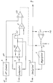
- an actuator 2 which can be controlled via a control element 1 is provided in the NF signal path AB of a car radio (not shown).
- the input of the control element 1 designed as an I controller is connected via a first electronic changeover switch S1 in its first switching position to the output of an operational amplifier V1 operated as a first level comparison stage, the inverting input of which is connected to the output of the actuator 2.
- the driving noise signal FG which is determined in a manner known per se, is fed to the non-inverting input.
- the electronic changeover switch S1 supplies the input of the control element 1 with a negative voltage constant.
- the output of an operational amplifier V2 operated as a second level comparison stage is connected to the control input of the electronic one Switch S1 and connected to a first reset input of an integrator 3.
- the output of the integrator 3 is connected to the inverting input of the operational amplifier V2, the non-inverting input of which is connected to the output of an LF envelope curve demodulator 4.
- the output of the envelope curve demodulator 4 is also connected to a second reset input of the integrator 3.
- Pulses i generated in a pulse generator (not shown) are fed to the input of the integrator 3.
- the first level comparison stage V1 forms, in a manner known per se, together with the control element 1 and the control element 2 a control circuit which strives to minimize the difference between the LF signal level and the driving noise level in the first switching position of S1.
- a signal taken from the LF signal path AB is fed to the LF envelope curve demodulator 4, which has a two-way rectifier and an arrangement for signal smoothing.
- the integrator output level IP rises continuously as long as it is smaller than the LF envelope curve level HP.
- the two levels IP and HP are compared with one another at arbitrary predeterminable time intervals ⁇ t. If IP becomes HP at the time of a query, the level IP in the integrator 3 is reset to the value of the level HP and the first changeover switch S1 is brought into the second switching position. The IP level now rises again until the next query.
- an offset voltage can be fed into the pause detection circuit by means of an adder 5.
- the control of the first switch S1 takes place here from the output of an operational amplifier V3 operated as a third level comparison stage, the non-inverting input of which is connected to the output of the envelope curve demodulator 4 and the inverting input of which is connected to the output of the adder 5.
- a second electronic changeover switch S2 controlled by the output of the second level comparison stage V2 connects an input of the adder 5 in a first switching position to the output of the integrator 3 and in a second switching position to the output of the envelope demodulator 4.
- V2 determined the envelope signal levels with the envelope signal levels raised by the amount of the offset voltage and outside the break compared the envelope curve levels with the integrator output levels raised by the amount of the offset voltage in the third level comparison stage. This achieves additional stabilization of the pause detection and the associated switchovers.
Abstract
Description
Die Erfindung betrifft ein Verfahren zur Anpassung der Lautstärke eines mobilen Wiedergabegerätes an das Umgebungsgeräusch nach dem Oberbegriff des Anspruchs 1.The invention relates to a method for adapting the volume of a mobile playback device to the ambient noise according to the preamble of
Mit einem derartigen Verfahren wird die Lautstärke entsprechend dem Geräuschpegel in der Umgebung des Lautsprechers so eingestellt, daß der Wiedergabepegel des Lautsprechers, also der Nutzsignalpegel, immer um einige Dezibel (dB) höher liegt als der Störgeräuschpegel, so daß das vom Lautsprecher abgestrahlte Nutzsignal von dem Hörenden, unabhängig von dem jeweiligen Grad der Umweltgeräusche, in etwa immer gleich laut empfunden wird. Insbesondere für den mobilen Betrieb des Lautsprechers bzw. des Rundfunkempfängers bedeutet das eine wesentliche Verbesserung des Komforts, da vermieden wird, daß der Hörende bei häufig wechselndem Geräuschpegel ständig die Lautstärke nachzustellen gezwungen ist.With such a method, the volume is adjusted according to the noise level in the vicinity of the loudspeaker so that the playback level of the loudspeaker, i.e. the useful signal level, is always a few decibels (dB) higher than the noise level, so that the useful signal emitted by the loudspeaker is from the Listeners, regardless of the level of environmental noise, are always about equally loud. Particularly for the mobile operation of the loudspeaker or the radio receiver, this means a significant improvement in comfort, since it is avoided that the listener is forced to constantly adjust the volume when the noise level changes frequently.
Der zur Anpassung der Lautstärke verwendete Regelkreis hat das Bestreben, ständig die Differenz zwischen dem NF- und dem Geräuschpegel zu minimieren. Bei eingeschwungener Regelung ist die Differenz minimal. Tritt jedoch beispielsweise im NF-Signal eine Pause bei gleichbleibendem Geräuschpegel auf, so nimmt die einer Pegelvergleichsschaltung entnommene Steuerspannung für den Regelkreis plötzlich einen hohen Wert an, der den Verstärkungsfaktor des Stellgliedes heraufsetzt bzw. die Durchgangsdämpfung des Stellgliedes herabsetzt. Wird nun die Pause schlagartig mit einem lauten NF-Einsatz beendet, so ist die Lautstärke kurzzeitig zu hoch; es tritt eine in der Wiedergabe als unangenehm empfundene Regelbewegung auf. Unter Pause ist hierbei ein Zeitabschnitt mit verschwindendem NF-Signalpegel gemeint, z. B. bei einem Sprachsignal eine Pause zwischen zwei Worten. Um die durch Pausen hervorgerufenen Störeffekte zu beheben, müssen die Pausen als solche erkannt werden. Bei der Ermittlung einer Pause mittels eines Schwellwertes ist es wenig sinnvoll, einen festen Schwellwert zu definieren, der für die größten auftretenden Störpegel noch ausreichend bemessen ist, da in diesem Fall bei der Wahl einer kaum gestörten NF-Quelle (z. B. CD) schwache NF-Passagen, die noch anhebungswürdig sind, unter diesen Schwellwert fallen. Bei einem für störarme NF-Quellen optimierten niedrigen festen Schwellwert kann hingegen bei qualitativ schlechteren NF-Quellen Rauschen als Nutzsignal gewertet und angehoben werden.The control loop used to adjust the volume strives to continuously minimize the difference between the LF and the noise level. The difference is minimal when the control is steady. However, if, for example, there is a pause in the LF signal with the noise level remaining the same, the control voltage for the control circuit, which is taken from a level comparison circuit, suddenly takes a high value, which increases the gain factor of the actuator or reduces the passage loss of the actuator. If the pause is suddenly ended with a loud NF use, the volume is temporarily too high; a control movement that is perceived as unpleasant occurs in the reproduction. A pause here means a period of time with a disappearing LF signal level, e.g. B. with a speech signal a pause between two words. To the through In order to eliminate perturbations caused by pauses, the pauses must be recognized as such. When determining a pause using a threshold value, it makes little sense to define a fixed threshold value that is still sufficiently dimensioned for the greatest interference levels that occur, since in this case, when choosing a hardly disturbed LF source (e.g. CD) weak NF passages that still need to be raised fall below this threshold. With a low fixed threshold value optimized for low-noise LF sources, on the other hand, noise can be evaluated and raised as a useful signal with poorer quality LF sources.
Der Erfindung liegt die Aufgabe zugrunde, ein Verfahren zur Anpassung der Lautstärke eines Autoradios an das Umgebungsgeräusch anzugeben, mit dem NF-Pausen sicher erkannt und durch diese bedingte Lautstärkensprünge weitgehend vermieden werden.The invention is based on the object of specifying a method for adapting the volume of a car radio to the ambient noise, with which NF pauses are reliably detected and, as a result, these volume jumps are largely avoided.
Diese Aufgabe wird erfindungsgemäß durch die im kennzeichnenden Teil des Anspruchs 1 angegebenen Maßnahmen gelöst.This object is achieved by the measures specified in the characterizing part of
Die mit der Erfindung erzielten Vorteile bestehen insbesondere darin, daß gemäß dem Verfahren NF-Signalpausen auch bei variierendem Störpegel sicher erkannt und somit als störend empfundene NF-Pegelsprünge weitgehend verhindert werden können.The advantages achieved by the invention consist in particular in that, according to the method, low-frequency signal pauses can be reliably recognized even with varying interference levels and thus largely avoided low-level jumps which are perceived as disturbing.
Weitere vorteilhafte Ausgestaltungen der Erfindung sind in den Unteransprüchen angegeben. Mit den in den Ansprüchen 2 und 3 angegebenen Maßnahmen wird bei einer relativ langen Pause der NF-Pegel spürbar abgesenkt. Dieses ist sinnvoll, da der Einsatzpegel der NF am Pausenende um so verschiedener - also auch lauter - vom NF-Pegel am Pausenanfang sein kann, je länger die Pause dauert. Bei einer relativ kurzen Pause ist der Unterschied hingegen an den Pausengrenzen mit großer Wahrscheinlichkeit klein, so daß keine größere Absenkung als Vorsichtsmaßnahme erforderlich ist. Mit den im Anspruch 4 angegebenen Maßnahmen läßt sich in vorteilhafter Weise die Pausenerkennung zusätzlich stabilisieren.Further advantageous embodiments of the invention are specified in the subclaims. With the measures specified in
Die Erfindung wird im folgenden anhand von ein Ausführungsbeispiel darstellenden Zeichnungen näher erläutert.The invention is explained in more detail below with reference to drawings showing an exemplary embodiment.
Es zeigen:
- Fig. 1
- Ein prinzipielles Blockschaltbild einer Einrichtung zur Anpassung der Lautstärke,
- Fig. 2
- ein Diagramm, welches den zeitlichen Ablauf von NF-Hüllkurvensignal und Integratorausgangssignal im Bereich einer gewerteten Signalpause darstellt und
- Fig. 3
- ein prinzipielles erweitertes Blockschaltbild einer Einrichtung, bei der einer Pegelvergleichsstufe eine Offset-Spannung zugeführt wird.
- Fig. 1
- A basic block diagram of a device for adjusting the volume,
- Fig. 2
- a diagram showing the temporal course of LF envelope signal and integrator output signal in the area of a weighted signal pause and
- Fig. 3
- a basic expanded block diagram of a device in which an offset voltage is supplied to a level comparison stage.
Im NF-Signalweg A-B eines nicht dargestellten Autoradios ist nach Fig. 1 ein über ein Regelglied 1 ansteuerbares Stellglied 2 vorgesehen. Der Eingang des als I-Regler ausgebildeten Regelgliedes 1 ist über einen ersten elektronischen Umschalter S1 in dessen erster Schaltstellung mit dem Ausgang eines als erste Pegelvergleichsstufe betriebenen Operationsverstärkers V1 verbunden, dessen invertierender Eingang mit dem Ausgang des Stellgliedes 2 verbunden ist. Dem nichtinvertierenden Eingang wird das in an sich bekannter Weise ermittelte Fahrgeräuschsignal FG zugeführt. In seiner zweiten Schaltstellung führt der elektronische Umschalter S1 dem Eingang des Regelgliedes 1 eine negative Spannungskonstante zu. Der Ausgang eines als zweite Pegelvergleichsstufe betriebenen Operationsverstärkers V2 ist mit dem Steuereingang des elektronischen Umschalters S1 sowie mit einem ersten Rücksetz-Eingang eines Integrators 3 verbunden. Der Ausgang des Integrators 3 ist mit dem invertierenden Eingang des Operationsverstärkers V2 verbunden, dessen nichtinvertierender Eingang mit dem Ausgang eines NF-Hüllkurvendemodulators 4 verbunden ist. Der Ausgang des Hüllkurvendemodulators 4 ist zudem mit einem zweiten Rücksetzeingang des Integrators 3 verbunden. Dem Eingang des Integrators 3 werden in einem nicht dargestellten Impulsgenerator erzeugte Impulse i zugeführt. Die erste Pegelvergleichsstufe V1 bildet in an sich bekannter Weise zusammen mit dem Regelglied 1 und dem Stellglied 2 einen Regelkreis, der bestrebt ist, in der ersten Schaltstellung von S1 die Differenz zwischen dem NF-Signalpegel und dem Fahrgeräuschpegel zu minimieren.According to FIG. 1, an
Zur Erkennung von Signalpausen oder diesen gleichzusetzenden leisen Musikpassagen wird ein dem NF-Signalweg A-B entnommenes Signal dem NF-Hüllkurvendemodulator 4, der einen Zweiweggleichrichter und eine Anordnung zur Signalglättung aufweist, zugeführt. Wie aus der Figur 2 zu ersehen ist, steigt der Integrator-Ausgangspegel IP, solange er kleiner als der NF-Hüllkurvenpegel HP ist, ständig an. Die beiden Pegel IP und HP werden in beliebig vorgebbaren Zeitabständen Δt miteinander verglichen. Wird zum Zeitpunkt einer Abfrage IP größer HP, so wird im Integrator 3 der Pegel IP auf den Wert des Pegels HP zurückgesetzt und der erste Umschalter S1 in die zweite Schaltstellung gebracht. Der Pegel IP steigt nun wieder bis zur nächsten Abfrage an. Solange IP größer HP ist, wird das Ausgangssignal von V2 negativ und der Pegel von IP bei der Abfrage auf den Pegel von HP zurückgesetzt. Bei IP kleiner HP wird der Pegelanstieg von IP ständig fortgesetzt, wobei das Ausgangssignal von V2 positiv ist. Ein negatives Ausgangssignal von V2 wird nun als Pause gewertet. Während der so gewerteten Pause wird die Regelschleife mittels des Umschalters S1 unterbrochen und das Regelglied von der negativen Spannungskonstante derart angesteuert, daß das Stellglied den Pegel des NF-Signals langsam absenkt. Mit dem Ende der Pause wird der Regelkreis wieder aktiviert. Es ist jedoch auch ohne weiteres möglich, den NF-Pegel während einer Pause nicht abzusenken, sondern ihn auch anderweitig zu beeinflussen sowie ihn konstant zu halten.To detect signal pauses or quiet music passages to be equated with this, a signal taken from the LF signal path AB is fed to the LF
Mit einer Erweiterung der Einrichtung nach Fig. 3 läßt sich mittels eines Addiergliedes 5 eine Offset-Spannung in die Pausenerkennungsschaltung einspeisen. Die Ansteuerung des ersten Umschalters S1 erfolgt hierbei vom Ausgang eines als dritte Pegelvergleichsstufe betriebenen Operationsverstärkers V3, dessen nichtinvertierender Eingang mit dem Ausgang des Hüllkurvendemodulators 4 und dessen invertierender Eingang mit dem Ausgang des Addiergliedes 5 verbunden ist. Ein vom Ausgang der zweiten Pegelvergleichsstufe V2 gesteuerter zweiter elektronischer Umschalter S2 verbindet einen Eingang des Addiergliedes 5 in einer ersten Schaltstellung mit dem Ausgang des Integrators 3 und in einer zweiten Schaltstellung mit dem Ausgang des Hüllkurvendemodulators 4. Durch diese Maßnahme werden während einer von der zweiten Pegelvergleichsstufe V2 ermittelten Pause die Hüllkurvensignalpegel mit den um den Betrag der Offset-Spannung angehobenen Hüllkurvensignalpegeln und außerhalb der Pause die Hüllkurvenpegel mit den um den Betrag der Offset-Spannung angehobenen Integrator-Ausgangspegeln in der dritten Pegelvergleichsstufe verglichen. Hiermit wird eine zusätzliche Stabilisierung der Pausenerkennung und der damit verbundenen Umschaltungen erreicht.With an expansion of the device according to FIG. 3, an offset voltage can be fed into the pause detection circuit by means of an adder 5. The control of the first switch S1 takes place here from the output of an operational amplifier V3 operated as a third level comparison stage, the non-inverting input of which is connected to the output of the
Claims (6)
dadurch gekennzeichnet,
daß in einer zweiten Pegelvergleichsstufe (V2) der Hüllkurvenpegel (HP) des NF-Signals mit einem ständig ansteigenden Ausgangssignal (IP) eines rücksetzbaren Integrators (3) in vorgegebenen Zeitabständen ( Δt) miteinander verglichen wird, daß, solange der Hüllkurvenpegel (HP) zu einem Vergleichszeitpunkt größer als der Integrator-Ausgangspegel (IP) ist, daß Integrator-Ausgangssignal (IP) weiter ansteigt sowie der Regelkreis wirksam geschaltet ist und daß, solange der Hüllkurvenpegel (HP) zu einem Vergleichszeitpunkt kleiner als der Integrator-Ausgangspegel (IP) ist, die
Regelschleife (1, 2, V1) des Regelkreises unwirksam geschaltet ist und daß der Integrator-Ausgangspegel (IP) auf den momentanen Wert des NF-Hüllkurvenpegels (HP) zurückgesetzt wird, von dem er bis zum nächsten Vergleichszeitpunkt ansteigt, und daß für die Dauer des als eine NF-Signalpause (T) gewerteten Zeitraums, dem Stellglied (2) ein den Pegel des NF-Signals beeinflussendes Steuersignal zugeführt wird und daß die Regelschleife (1, 2, V1) unmittelbar nach Beendigung einer NF-Signalpause (T) wieder wirksam wird.Method for adapting the volume of a mobile playback device, in particular car radios, to the ambient noise, the LF signal level present behind an actuator arranged in the LF signal path and the driving noise signal level being fed to a first level comparison stage, which uses a control element and the actuator to provide a control circuit tends to minimize the difference between the LF signal level and the driving noise signal level,
characterized,
that in a second level comparison stage (V2) the envelope level (HP) of the LF signal is compared with a constantly increasing output signal (IP) of a resettable integrator (3) at predetermined time intervals (Δt), that as long as the envelope level (HP) increases a comparison time is greater than the integrator output level (IP), the integrator output signal (IP) continues to rise and the control circuit is activated and that as long as the envelope level (HP) is lower than the integrator output level (IP) at a comparison time , the
Control loop (1, 2, V1) of the control circuit is ineffective and that the integrator output level (IP) is reset to the current value of the LF envelope curve level (HP), from which it increases until the next comparison time, and for the duration of the period evaluated as an LF signal pause (T), a control signal influencing the level of the LF signal is fed to the actuator (2) and that the control loop (1, 2, V1) again immediately after an LF signal pause (T) has ended takes effect.
dadurch gekennzeichnet,
daß während der Dauer einer NF-Signalpause (T) der NF-Pegel im NF-Signalweg (A-B) langsam abgesenkt wird.Method for adjusting the volume according to claim 1,
characterized,
that the LF level in the LF signal path (AB) is slowly lowered during the duration of an LF signal pause (T).
dadurch gekennzeichnet,
daß das dem Stellglied (2) während der Dauer einer NF-Signalpause (T) zugeführte externe Steuersignal derart beschaffen ist, daß es den NF-Signalpegel stetig absenkt.Method for adjusting the volume according to one of claims 1 or 2,
characterized,
that the external control signal supplied to the actuator (2) during the duration of an LF signal pause (T) is such that it constantly lowers the LF signal level.
dadurch gekennzeichnet,
daß die Umschaltung der Regelschleife (1, 2, V1) über eine dritte Pegelvergleichsstufe (V3) erfolgt, in der der Hüllkurvenpegel (HP) außerhalb einer von der zweiten Pegelvergleichsstufe (V2) ermittelten NF-Signalpause (T) mit dem um einen Offset-Spannungsbetrag angehobenen Integrator-Ausgangssignal (IP) und innerhalb einer ermittelten NF-Signalpause (T) mit dem um einen Offset-Spannungsbetrag angehobenen Hüllkurven-Signal (HP) verglichen wird, wobei diese Signale der dritten Pegelvergleichsstufe (V3) über ein Additionsglied (5) zugeführt werden, welches die Signale um den Betrag einer Offset-Spannung anhebt.Method for adjusting the volume according to one of claims 1 to 3,
characterized,
that the switching of the control loop (1, 2, V1) takes place via a third level comparison stage (V3), in which the envelope curve level (HP) outside of an LF signal pause (T) determined by the second level comparison stage (V2) with the by an offset Voltage amount raised integrator output signal (IP) and within a determined LF signal pause (T) is compared with the envelope signal (HP) raised by an offset voltage amount, these signals of the third level comparison stage (V3) via an addition element (5) are supplied, which raises the signals by the amount of an offset voltage.
dadurch gekennzeichnet,
daß die Eingangsklemme für das NF-Signal über einen Hüllkurvendemodulator (4) mit dem ersten Eingang der zweiten Pegelvergleichsstufe (V2) verbunden ist, daß der Ausgang des Integrators (3) mit dem zweiten Eingang der zweiten Pegelvergleichsstufe (V2) verbunden ist, daß der Ausgang der zweiten Pegelvergleichsstufe (V2) mit dem Steuereingang des ersten elektronischen Umschalters (S1) sowie mit einem zur Rücksetzung vorgesehenen Steuereingang des Integrators (3) verbunden ist. Daß der Ausgang des Hüllkurvendemodulators (4) mit einem weiteren Steuereingang des Integrators (3) verbunden ist und daß der Eingang des Integrators (3) mit einer Impulsquelle verbunden ist.Device for carrying out a method according to one of Claims 1 to 3, in which the input of the control element can be connected via an electronically controllable changeover switch in a first switch position to the output of the first level comparison stage and a second switch position to a control voltage source,
characterized,
that the input terminal for the AF signal is connected via an envelope demodulator (4) to the first input of the second level comparison stage (V2), that the output of the integrator (3) is connected to the second input of the second level comparison stage (V2), that the Output of the second level comparison stage (V2) is connected to the control input of the first electronic switch (S1) and to a control input of the integrator (3) provided for resetting. That the output of the envelope curve demodulator (4) is connected to a further control input of the integrator (3) and that the input of the integrator (3) is connected to a pulse source.
dadurch gekennzeichnet,
daß die Eingangsklemme für das NF-Signal über einen Hüllkurvendemodulator (4) mit dem ersten Eingang der zweiten Pegelvergleichsstufe (V2) verbunden ist, daß der Ausgang des Integrators (3) mit dem zweiten Eingang der zweiten Pegelvergleichsstufe (V2) verbunden ist, daß der Ausgang der zweiten Pegelvergleichsstufe (V2) mit dem Steuereingang eines zweiten elektronischen Umschalters (S2) sowie mit dem zur Rücksetzung vorgesehenen Steuereingang des Integrators (3) verbunden ist, daß der Ausgang der dritten Pegelvergleichsstufe (V3) mit dem Steuereingang des ersten elektronischen Umschalters (S1) verbunden ist, daß der erste Eingang der dritten Pegelvergleichsstufe mit dem Ausgang des Hüllkurvendemodulators (4) verbunden ist, daß der zweite Eingang der dritten Pegelvergleichsstufe (V3) mit dem Ausgang des Addiergliedes (5) verbunden ist, dessen einer Eingang über den zweiten elektronischen Umschalter (S2) an den Ausgang des Integrators (3) bzw. an den Ausgang des Hüllkurvendemodulators (4) legbar ist.Device for carrying out a method according to claim 4, in which the input of the control element can be connected via an electronically controllable first switch in a first switching position to the output of the first level comparison stage and in a second switching position to a control voltage source,
characterized,
that the input terminal for the AF signal is connected via an envelope demodulator (4) to the first input of the second level comparison stage (V2), that the output of the integrator (3) is connected to the second input of the second level comparison stage (V2), that the Output of the second level comparison stage (V2) with the control input of a second electronic Switch (S2) and to the control input of the integrator (3) provided for resetting, that the output of the third level comparison stage (V3) is connected to the control input of the first electronic switch (S1), that the first input of the third level comparison stage is connected to the Output of the envelope demodulator (4) is connected, that the second input of the third level comparison stage (V3) is connected to the output of the adder (5), one input of which via the second electronic switch (S2) to the output of the integrator (3) or . can be placed at the output of the envelope curve demodulator (4).
Applications Claiming Priority (2)
| Application Number | Priority Date | Filing Date | Title |
|---|---|---|---|
| DE4328798A DE4328798C2 (en) | 1993-08-27 | 1993-08-27 | Method and device for adjusting the volume of a mobile playback device to the ambient noise |
| DE4328798 | 1993-08-27 |
Publications (2)
| Publication Number | Publication Date |
|---|---|
| EP0641070A1 true EP0641070A1 (en) | 1995-03-01 |
| EP0641070B1 EP0641070B1 (en) | 1999-02-03 |
Family
ID=6496129
Family Applications (1)
| Application Number | Title | Priority Date | Filing Date |
|---|---|---|---|
| EP94105948A Expired - Lifetime EP0641070B1 (en) | 1993-08-27 | 1994-04-18 | Method and circuit for the adjustment of the level of sound sources in accordance with the ambient noise level |
Country Status (5)
| Country | Link |
|---|---|
| US (1) | US5550922A (en) |
| EP (1) | EP0641070B1 (en) |
| JP (1) | JPH0786857A (en) |
| AT (1) | ATE176560T1 (en) |
| DE (2) | DE4328798C2 (en) |
Families Citing this family (12)
| Publication number | Priority date | Publication date | Assignee | Title |
|---|---|---|---|---|
| US5907622A (en) * | 1995-09-21 | 1999-05-25 | Dougherty; A. Michael | Automatic noise compensation system for audio reproduction equipment |
| JP3482123B2 (en) * | 1998-04-27 | 2003-12-22 | 富士通テン株式会社 | Sound equipment |
| US7212640B2 (en) | 1999-11-29 | 2007-05-01 | Bizjak Karl M | Variable attack and release system and method |
| US7190292B2 (en) * | 1999-11-29 | 2007-03-13 | Bizjak Karl M | Input level adjust system and method |
| US6870830B1 (en) | 2000-11-30 | 2005-03-22 | 3Com Corporation | System and method for performing messaging services using a data communications channel in a data network telephone system |
| US7553288B2 (en) * | 2003-03-10 | 2009-06-30 | Cohen Daniel E | Sound and vibration transmission pad and system |
| US8668045B2 (en) * | 2003-03-10 | 2014-03-11 | Daniel E. Cohen | Sound and vibration transmission pad and system |
| NZ542420A (en) * | 2003-03-10 | 2008-03-28 | Daniel E Cohen | Sound and vibration transmission pad and system |
| US8195095B2 (en) * | 2006-05-19 | 2012-06-05 | International Business Machines Corporation | Mitigating audible acknowledgement volume in a vehicle security system |
| US8249271B2 (en) * | 2007-01-23 | 2012-08-21 | Karl M. Bizjak | Noise analysis and extraction systems and methods |
| EP3232688A1 (en) | 2016-04-12 | 2017-10-18 | Fraunhofer-Gesellschaft zur Förderung der angewandten Forschung e.V. | Apparatus and method for providing individual sound zones |
| DE102016220365B4 (en) * | 2016-10-18 | 2022-02-17 | Audi Ag | Method for operating an audio output device, audio output device for a motor vehicle and motor vehicle |
Citations (2)
| Publication number | Priority date | Publication date | Assignee | Title |
|---|---|---|---|---|
| FR2370376A1 (en) * | 1976-11-08 | 1978-06-02 | Philips Nv | DEVICE INTENDED TO AMPLIFY ACOUSTIC SIGNALS AND EQUIPPED WITH MEANS TO REMOVE UNDESIRABLE PARASITE SIGNALS |
| EP0141129A2 (en) * | 1983-09-22 | 1985-05-15 | Blaupunkt-Werke GmbH | Method of adapting the sound volume of a loudspeaker in accordance with the ambiant noise level |
Family Cites Families (5)
| Publication number | Priority date | Publication date | Assignee | Title |
|---|---|---|---|---|
| JPS57136811A (en) * | 1981-02-18 | 1982-08-24 | Nissan Motor Co Ltd | Automatic controller of sound volume |
| DE3426068A1 (en) * | 1983-09-22 | 1985-04-11 | Blaupunkt-Werke Gmbh, 3200 Hildesheim | METHOD FOR ADJUSTING THE VOLUME OF A SPEAKER TO AN INTERFERENCE NOISE LEVEL RULING AT THE SPEAKER LOCATION |
| JPH034611A (en) * | 1989-06-01 | 1991-01-10 | Pioneer Electron Corp | On-vehicle automatic sound volume adjustment device |
| US5054078A (en) * | 1990-03-05 | 1991-10-01 | Motorola, Inc. | Method and apparatus to suspend speech |
| US5243657A (en) * | 1992-07-31 | 1993-09-07 | Brian Cotton | Automatic microphone sensitivity control circuit |
-
1993
- 1993-08-27 DE DE4328798A patent/DE4328798C2/en not_active Expired - Fee Related
-
1994
- 1994-04-18 EP EP94105948A patent/EP0641070B1/en not_active Expired - Lifetime
- 1994-04-18 DE DE59407761T patent/DE59407761D1/en not_active Expired - Lifetime
- 1994-04-18 AT AT94105948T patent/ATE176560T1/en not_active IP Right Cessation
- 1994-08-10 US US08/288,563 patent/US5550922A/en not_active Expired - Fee Related
- 1994-08-26 JP JP6202347A patent/JPH0786857A/en active Pending
Patent Citations (2)
| Publication number | Priority date | Publication date | Assignee | Title |
|---|---|---|---|---|
| FR2370376A1 (en) * | 1976-11-08 | 1978-06-02 | Philips Nv | DEVICE INTENDED TO AMPLIFY ACOUSTIC SIGNALS AND EQUIPPED WITH MEANS TO REMOVE UNDESIRABLE PARASITE SIGNALS |
| EP0141129A2 (en) * | 1983-09-22 | 1985-05-15 | Blaupunkt-Werke GmbH | Method of adapting the sound volume of a loudspeaker in accordance with the ambiant noise level |
Non-Patent Citations (1)
| Title |
|---|
| T. TANIYAMA: "Automatic loudness adjusting circuits for automotive audio systems.", IEEE TRANSACTIONS ON CONSUMER ELECTRONICS, vol. CE-27, no. 3, August 1981 (1981-08-01), NEW YORK US, pages 227 - 233, XP011153262 * |
Also Published As
| Publication number | Publication date |
|---|---|
| DE4328798A1 (en) | 1995-03-16 |
| JPH0786857A (en) | 1995-03-31 |
| US5550922A (en) | 1996-08-27 |
| DE4328798C2 (en) | 1997-01-16 |
| EP0641070B1 (en) | 1999-02-03 |
| DE59407761D1 (en) | 1999-03-18 |
| ATE176560T1 (en) | 1999-02-15 |
Similar Documents
| Publication | Publication Date | Title |
|---|---|---|
| DE1487276C3 (en) | Module for a circuit arrangement for influencing the dynamics of audio signals through compression or expansion for the purpose of conveying background noise | |
| DE19611026C1 (en) | Noise suppression for hearing aid with signal level dependent AGC | |
| EP0641070B1 (en) | Method and circuit for the adjustment of the level of sound sources in accordance with the ambient noise level | |
| DE3904505C2 (en) | Noise suppression system for MW radio receivers | |
| DE2711524C2 (en) | Circuit arrangement for noise suppression in an FM receiver | |
| EP0027519A1 (en) | Circuit arrangement for the automatic volume control of a loudspeaker in dependence upon an interference noise level prevailing at the loudspeaker's location | |
| DE3019145C2 (en) | ||
| CH656994A5 (en) | CIRCUIT FOR NOISE REDUCTION, ESPECIALLY FOR SIGNAL RECORDING / PLAYBACK DEVICES. | |
| EP0069843B2 (en) | Lf amplifier for a television receiver | |
| EP0483701A2 (en) | Method of noise reduction in hearing aids | |
| AT403978B (en) | SINGLE CHANNEL CIRCUIT FOR A HEARING AID | |
| DE2752657C2 (en) | ||
| EP0364711B1 (en) | Signal level adjustment circuit arrangement | |
| EP0881779A2 (en) | Method and circuit for detecting multipath interference at FM broadcast reception | |
| DE3017781C2 (en) | ||
| DE4326097C2 (en) | Circuit arrangement for briefly muting the playback in a radio receiver | |
| DE3537837C1 (en) | Circuit arrangement for noise suppression with minimum volume of a low frequency amplifier | |
| EP1274175B1 (en) | Method of checking the reception of alternative reception frequencies in a car radio and car radio | |
| DE4421694B4 (en) | Circuit arrangement for a car radio for generating short-term mute pulses | |
| CH657485A5 (en) | NOISE REDUCTION CIRCUIT. | |
| DE19804922A1 (en) | Method and device for controlling the gain in a signal processing system | |
| DE2917100C2 (en) | Fade-in / fade-out switch for an audio amplifier | |
| DE4215420C2 (en) | Properly sound volume control circuit | |
| DE3008033A1 (en) | Crackle suppression system for ear testing equipment - uses transistors and resistance capacity members to control level and frequency regulating switches | |
| DE19617651A1 (en) | Circuit arrangement for the detection of signal pauses |
Legal Events
| Date | Code | Title | Description |
|---|---|---|---|
| PUAI | Public reference made under article 153(3) epc to a published international application that has entered the european phase |
Free format text: ORIGINAL CODE: 0009012 |
|
| AK | Designated contracting states |
Kind code of ref document: A1 Designated state(s): AT DE FR GB IT |
|
| 17P | Request for examination filed |
Effective date: 19950901 |
|
| 17Q | First examination report despatched |
Effective date: 19971126 |
|
| GRAG | Despatch of communication of intention to grant |
Free format text: ORIGINAL CODE: EPIDOS AGRA |
|
| GRAG | Despatch of communication of intention to grant |
Free format text: ORIGINAL CODE: EPIDOS AGRA |
|
| GRAH | Despatch of communication of intention to grant a patent |
Free format text: ORIGINAL CODE: EPIDOS IGRA |
|
| GRAH | Despatch of communication of intention to grant a patent |
Free format text: ORIGINAL CODE: EPIDOS IGRA |
|
| GRAA | (expected) grant |
Free format text: ORIGINAL CODE: 0009210 |
|
| AK | Designated contracting states |
Kind code of ref document: B1 Designated state(s): AT DE FR GB IT |
|
| REF | Corresponds to: |
Ref document number: 176560 Country of ref document: AT Date of ref document: 19990215 Kind code of ref document: T |
|
| REF | Corresponds to: |
Ref document number: 59407761 Country of ref document: DE Date of ref document: 19990318 |
|
| ET | Fr: translation filed | ||
| GBV | Gb: ep patent (uk) treated as always having been void in accordance with gb section 77(7)/1977 [no translation filed] |
Effective date: 19990203 |
|
| ITF | It: translation for a ep patent filed |
Owner name: F.T.IST.ART.90 ALLEGATA;STUDIO JAUMANN P. & C. S.N |
|
| REG | Reference to a national code |
Ref country code: GB Ref legal event code: 710B |
|
| PLBE | No opposition filed within time limit |
Free format text: ORIGINAL CODE: 0009261 |
|
| STAA | Information on the status of an ep patent application or granted ep patent |
Free format text: STATUS: NO OPPOSITION FILED WITHIN TIME LIMIT |
|
| 26N | No opposition filed | ||
| GBT | Gb: translation of ep patent filed (gb section 77(6)(a)/1977) |
Effective date: 20000323 |
|
| REG | Reference to a national code |
Ref country code: GB Ref legal event code: 911A Free format text: FOLLOWING A REQUEST UNDER RULE 110(4) OF THE RULES 1995 TO EXTEND THE PERIOD FOR FILING A TRANSLATION OF THE SPECIFICATION, A TRANSLATION HAS NOW BEEN FILED IN ACCORDANCE WITH SECTION 77(6)(A). THIS PATENT WAS ANNOUNCED AS VOID IN THE PATENTS AND DESIGNS JOURNAL DATED 04.08.1999. THE PATENT IS NOW REINSTATED WITH A GRANT DATE EFFECTIVE IN THE UK OF 03.02.1999. |
|
| REG | Reference to a national code |
Ref country code: GB Ref legal event code: IF02 |
|
| PGFP | Annual fee paid to national office [announced via postgrant information from national office to epo] |
Ref country code: GB Payment date: 20050407 Year of fee payment: 12 |
|
| PGFP | Annual fee paid to national office [announced via postgrant information from national office to epo] |
Ref country code: AT Payment date: 20050421 Year of fee payment: 12 |
|
| PG25 | Lapsed in a contracting state [announced via postgrant information from national office to epo] |
Ref country code: GB Free format text: LAPSE BECAUSE OF NON-PAYMENT OF DUE FEES Effective date: 20060418 Ref country code: AT Free format text: LAPSE BECAUSE OF NON-PAYMENT OF DUE FEES Effective date: 20060418 |
|
| PGFP | Annual fee paid to national office [announced via postgrant information from national office to epo] |
Ref country code: IT Payment date: 20060430 Year of fee payment: 13 |
|
| GBPC | Gb: european patent ceased through non-payment of renewal fee |
Effective date: 20060418 |
|
| PGFP | Annual fee paid to national office [announced via postgrant information from national office to epo] |
Ref country code: FR Payment date: 20080418 Year of fee payment: 15 |
|
| PG25 | Lapsed in a contracting state [announced via postgrant information from national office to epo] |
Ref country code: IT Free format text: LAPSE BECAUSE OF NON-PAYMENT OF DUE FEES Effective date: 20070418 |
|
| REG | Reference to a national code |
Ref country code: FR Ref legal event code: ST Effective date: 20091231 |
|
| PG25 | Lapsed in a contracting state [announced via postgrant information from national office to epo] |
Ref country code: FR Free format text: LAPSE BECAUSE OF NON-PAYMENT OF DUE FEES Effective date: 20091222 |
|
| PGFP | Annual fee paid to national office [announced via postgrant information from national office to epo] |
Ref country code: DE Payment date: 20100624 Year of fee payment: 17 |
|
| REG | Reference to a national code |
Ref country code: DE Ref legal event code: R119 Ref document number: 59407761 Country of ref document: DE |
|
| REG | Reference to a national code |
Ref country code: DE Ref legal event code: R119 Ref document number: 59407761 Country of ref document: DE |
|
| PG25 | Lapsed in a contracting state [announced via postgrant information from national office to epo] |
Ref country code: DE Free format text: LAPSE BECAUSE OF NON-PAYMENT OF DUE FEES Effective date: 20111031 |