EP0640367A1 - Destillationskolonne zur Trennung eines Flüssigkeitsgemisches in mehrere reine Fraktionen - Google Patents
Destillationskolonne zur Trennung eines Flüssigkeitsgemisches in mehrere reine Fraktionen Download PDFInfo
- Publication number
- EP0640367A1 EP0640367A1 EP94112560A EP94112560A EP0640367A1 EP 0640367 A1 EP0640367 A1 EP 0640367A1 EP 94112560 A EP94112560 A EP 94112560A EP 94112560 A EP94112560 A EP 94112560A EP 0640367 A1 EP0640367 A1 EP 0640367A1
- Authority
- EP
- European Patent Office
- Prior art keywords
- distillation column
- separating device
- liquid
- walls
- column according
- Prior art date
- Legal status (The legal status is an assumption and is not a legal conclusion. Google has not performed a legal analysis and makes no representation as to the accuracy of the status listed.)
- Granted
Links
- 238000004821 distillation Methods 0.000 title claims abstract description 32
- 239000007788 liquid Substances 0.000 title claims abstract description 15
- 239000000203 mixture Substances 0.000 title claims abstract description 9
- 239000007789 gas Substances 0.000 claims description 15
- 238000000926 separation method Methods 0.000 claims description 8
- 239000000463 material Substances 0.000 claims description 7
- 238000012856 packing Methods 0.000 claims description 7
- IJGRMHOSHXDMSA-UHFFFAOYSA-N Atomic nitrogen Chemical compound N#N IJGRMHOSHXDMSA-UHFFFAOYSA-N 0.000 claims description 4
- 125000006850 spacer group Chemical group 0.000 claims description 3
- 229910052757 nitrogen Inorganic materials 0.000 claims description 2
- 238000005192 partition Methods 0.000 abstract 2
- 238000009835 boiling Methods 0.000 description 4
- 238000000034 method Methods 0.000 description 4
- 239000011261 inert gas Substances 0.000 description 3
- 238000010276 construction Methods 0.000 description 1
- 230000001419 dependent effect Effects 0.000 description 1
- 238000007700 distillative separation Methods 0.000 description 1
- 210000002196 fr. b Anatomy 0.000 description 1
- 210000003918 fraction a Anatomy 0.000 description 1
- 210000000540 fraction c Anatomy 0.000 description 1
- 239000000126 substance Substances 0.000 description 1
Images

Classifications
-
- B—PERFORMING OPERATIONS; TRANSPORTING
- B01—PHYSICAL OR CHEMICAL PROCESSES OR APPARATUS IN GENERAL
- B01D—SEPARATION
- B01D3/00—Distillation or related exchange processes in which liquids are contacted with gaseous media, e.g. stripping
- B01D3/14—Fractional distillation or use of a fractionation or rectification column
- B01D3/141—Fractional distillation or use of a fractionation or rectification column where at least one distillation column contains at least one dividing wall
-
- B—PERFORMING OPERATIONS; TRANSPORTING
- B01—PHYSICAL OR CHEMICAL PROCESSES OR APPARATUS IN GENERAL
- B01D—SEPARATION
- B01D3/00—Distillation or related exchange processes in which liquids are contacted with gaseous media, e.g. stripping
- B01D3/14—Fractional distillation or use of a fractionation or rectification column
- B01D3/32—Other features of fractionating columns ; Constructional details of fractionating columns not provided for in groups B01D3/16 - B01D3/30
-
- Y—GENERAL TAGGING OF NEW TECHNOLOGICAL DEVELOPMENTS; GENERAL TAGGING OF CROSS-SECTIONAL TECHNOLOGIES SPANNING OVER SEVERAL SECTIONS OF THE IPC; TECHNICAL SUBJECTS COVERED BY FORMER USPC CROSS-REFERENCE ART COLLECTIONS [XRACs] AND DIGESTS
- Y10—TECHNICAL SUBJECTS COVERED BY FORMER USPC
- Y10S—TECHNICAL SUBJECTS COVERED BY FORMER USPC CROSS-REFERENCE ART COLLECTIONS [XRACs] AND DIGESTS
- Y10S203/00—Distillation: processes, separatory
- Y10S203/20—Power plant
Definitions
- the invention relates to a distillation column for separating a liquid mixture into several pure fractions, the distillation column being divided into two parts, an inlet and a removal part, in its central region by a separating device which is effective in the longitudinal direction.
- distillation column With such a distillation column, it is possible to separate a multicomponent mixture into several pure fractions in only one column.
- a disadvantage of the process described is that a heat flow through the separating device from the warmer to the colder part occurs in distillations with high temperature differences between the inlet and the outlet part. As a result, the separation performance of the distillation column drops as a result of the distribution of energy and the energy required to achieve the desired separation result increases.
- the invention is therefore based on the object of avoiding the disadvantages mentioned.
- the separating device consists of two walls with a gas space between them, the distance between the two walls being 1 to 50 mm, preferably 3 to 10 mm.
- the heat flow through the separating device is reduced or, in the best case, even prevented.
- a distillation column 1 is divided into an inlet section 2 and a removal section 3 by two walls 4 attached in the longitudinal direction. Between the two walls there is a gas space 5, which is either gas-tight with respect to the distillation space or is purged with an inert gas, for example nitrogen.
- the inert gas 6/7 preferably enters at the upper end of the gas space and is preferably conducted into the distillation space at the lower end of the gas space. It is also possible to fill the gas space 5 with a material with low thermal conductivity or to place spacers in the gas space between the two walls to increase the mechanical stability.
- the gas space can be flushed with inert gas as described above, or preferably sealed and evacuated in relation to the distillation space.
- the multicomponent mixture A, B, C is added to the feed section 2 and separated into the pure fractions in the distillation column 1 in accordance with the boiling sequence.
- the low-boiling fraction A is withdrawn from column 1 as the top product and the heaviest boiling fraction C as the bottom product.
- the medium-boiling fraction B is withdrawn as a side draw from the removal part 3.
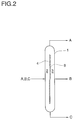
- the separating device is designed in such a way that liquid deflectors 8 are attached to one or both sides of the separating device 4, if necessary in sections, in such a way that the separating device cannot be wetted by the liquid.
- the liquid deflectors 8 are expediently attached to the side on which the lower operating temperature in There is a comparison between inlet part 2 and withdrawal part 3.
- the liquid deflectors 8 can also be attached to the pack. If wire mesh or perforated material is used as the packing material, the liquid deflectors are preferably designed such that there is a higher flow pressure loss between the separating device and the packing than in the packing.
Landscapes
- Chemical & Material Sciences (AREA)
- Chemical Kinetics & Catalysis (AREA)
- Vaporization, Distillation, Condensation, Sublimation, And Cold Traps (AREA)
- Separation By Low-Temperature Treatments (AREA)
- Organic Low-Molecular-Weight Compounds And Preparation Thereof (AREA)
Abstract
Description
- Die Erfindung betrifft eine Destillationskolonne zur Trennung eines Flüssigkeitsgemisches in mehrere reine Fraktionen, wobei die Destillationskolonne in ihrem mittleren Bereich durch eine in Längsrichtung wirksame Trenneinrichtung in 2 Teile, einen Zulauf- und einen Entnahmeteil, unterteilt ist.
- Die destillative Auftrennung von Mehrstoffgemischen ist in der Literatur vielfach beschrieben. So wird beispielsweise in Ullmann's Encyclopädie die Technische Chemie, 5. Auflage, Band B 3, Seite 58 ff die Auftrennung von Mehrstoffgemischen durch Hintereinanderschaltung mehrerer Destillationskolonnen beschrieben. Nachteilig an diesem Verfahren ist der hohe apparative Aufwand durch den Bau mehrerer Destillationskolonnnen. In der Zeitschrift Chemie-Ingenieur-Technik 61 (1989), Nr. 2, Seiten 104 - 112 wird ein Verfahren zur destillativen Auftrennung eines Mehrstoffgemisches in mehrere Fraktionen beschrieben, bei dem eine Destillationskolonne mit einer in Längsrichtung wirksamen Trenneinrichtung versehen ist, wodurch die Destillationskolonne in einen Zulauf- und einen Entnahmeteil unterteilt wird. Mit einer derartigen Destillationskolonne ist es möglich, ein Mehrstoffgemisch in nur einer Kolonne in mehrere reine Fraktionen zu trennen. Nachteilig bei dem beschriebenen Verfahren ist, daß es bei Destillationen mit hohen Temperaturdifferenzen zwischen Zulauf- und Entnahmeteil zu einem Wärmestrom durch die Trenneinrichtung hindurch von dem wärmeren in den kälteren Teil kommt. Dadurch sinkt infolge von Maldistribution die Trennleistung der Destillationskolonne und der Energiebedarf zur Erzielung des gewünschten Trennergebnisses steigt an.
- Die Erfindung liegt daher die Aufgabe zugrunde, die genannten Nachteile zu vermeiden.
- Diese Aufgabe wird erfindungsgemäß dadurch gelöst, daß die Trenneinrichtung aus zwei Wänden mit dazwischen liegendem Gasraum besteht, wobei der Abstand der beiden Wände 1 bis 50 mm, bevorzugt 3 - 10 mm, beträgt.
- Weitere Merkmale des erfindungsgemäßen Verfahrens sind Gegenstand der Unteransprüche.
- Mittels der erfindungsgemäßen Trenneinrichtung wird der Wärmestrom durch die Trenneinrichtung hindurch verringert oder im günstigsten Fall sogar verhindert.
- Ausführungsbeispiele der Erfindung sind in den Zeichnungen schematisch dargestellt und werden im folgenden näher beschrieben.
- Es zeigen
- Figur 1
Eine Destillationskolonne mit in Längsrichtung wirkender Trenneinrichtung, bei welcher die Trenneinrichtung aus zwei Wänden mit dazwischenliegendem Gasraum besteht. - Figur 2
Eine Destillationskolonne mit in Längsrichtung wirkender Trenneinrichtung, bei welcher die Trenneinrichtung aus einer Wand mit Flüssigkeitsabweisern besteht. - Gemäß Figur 1 wird eine Destillationskolonne 1 durch zwei in Längsrichtung angebrachte Wände 4 in einen Zulaufteil 2 und einen Entnahmeteil 3 unterteilt. Zwischen den beiden Wänden befindet sich ein Gasraum 5, welcher gegenüber dem Destillationsraum entweder gasdicht abgeschlossen ist oder aber mit einem inerten Gas, beispielsweise Stickstoff gespült wird. Das Inertgas 6/7 tritt dabei vorzugsweise am oberen Ende des Gasraums ein und wird bevorzugt am unteren Ende des Gasraums in den Destillationsraum geleitet. Möglich ist auch das Ausfüllen des Gasraums 5 durch ein Material mit geringer Wärmeleitfähigkeit oder die Anbringung von Abstandshaltern im Gasraum zwischen den beiden Wänden zur Erhöhung der mechanischen Stabilität. Bei einer Ausführung mit Abstandshaltern im Gasraum kann der Gasraum wie oben beschrieben mit Inertgas gespült werden oder aber vorzugsweise gegenüber dem Destillationsraum gasdicht abgeschlossen und evakuiert werden. Das Mehrstoffgemisch A, B, C wird in den Zulaufteil 2 zugegeben und in der Destillationskolonne 1 entsprechend der Siedefolge in die reinen Fraktionen getrennt. Die leichtestsiedende Fraktion A wird als Kopfprodukt und die schwerstsiedende Fraktion C als Sumpfprodukt aus der Kolonne 1 abgezogen. Die mittelsiedende Fraktion B wird als Seitenabzug aus dem Entnahmeteil 3 abgezogen.
- Gemäß Figur 2 wird die Trenneinrichtung so ausgeführt, daß auf einer oder auf beiden Seiten der Trenneinrichtung 4 Flüssigkeitsabweiser 8 - gegebenenfalls abschnittsweise - so angebracht werden, daß die Trenneinrichtung nicht von der Flüssigkeit benetzt werden kann. Zweckmäßig werden die Flüssigkeitsabweiser 8 auf der Seite angebracht, auf welcher die tiefere Betriebstemperatur im Vergleich zwischen Zulaufteil 2 und Entnahmeteil 3 herrscht. Bei der Verwendung von geordneten Packungen können die Flüssigkeitsabweiser 8 auch an der Packung angebracht werden. Wenn als Packungsmaterial Drahtgewebe oder perforiertes Material verwendet wird, werden die Flüssigkeitsabweiser bevorzugt konstruktiv so ausgeführt, daß zwischen der Trenneinrichtung und der Packung ein höherer Durchströmungsdruckverlust herrscht als in der Packung.
Claims (9)
- Destillationskolonne zur Trennung eines Flüssigkeitsgemisches in mehrere reine Fraktionen, wobei die Destillationskolonne in ihrem mittleren Bereich durch eine in Längsrichtung wirksame Trenneinrichtung in 2 Teile, einen Zulauf- und einen Entnahmeteil, unterteilt ist, dadurch gekennzeichnet, daß die Trenneinrichtung aus zwei Wänden mit dazwischen liegendem Gasraum besteht, wobei der Abstand der beiden Wände 1 bis 50 mm, bevorzugt 3 bis 10 mm, beträgt.
- Destillationskolonne nach Anspruch 1, dadurch gekennzeichnet, daß die beiden Wände eben ausgeführt, parallel angeordnet und mit dazwischen liegenden Abstandshaltern ausgeführt sind.
- Destillationskolonne nach den Ansprüchen 1 bis 2, dadurch gekennzeichnet, daß der zwischen den beiden Wänden der Trenneinrichtung liegende Gasraum gegenüber dem Destillationsraum gasdicht abgetrennt ist und der Druck im Gasraum gleich hoch oder bevorzugt niedriger ist als der Druck im Destillationsraum.
- Destillationskolonne nach den Ansprüchen 1 bis 3, dadurch gekennzeichnet, daß die Trenneinrichtung aus zwei parallelen Wänden besteht, zwischen denen ein Material mit geringerer Wärmeleitfähigkeit als die der Wände angeordnet ist.
- Destillationskolonne nach den Ansprüchen 1 bis 4, dadurch gekennzeichnet, daß an einem Ende der Trenneinrichtung, bevorzugt dem oberen Ende, ein Gasstrom, bevorzugt Stickstoff, eingeleiet wird und bevorzugt am entgegengesetzten Ende aus der Trenneinrichtung austritt und direkt in die Kolonne oder am Kopf der Kolonne eingeleitet wird.
- Destillationskolonne nach den Ansprüchen 1 bis 5, dadurch gekennzeichnet, daß auf einer Seite oder auf beiden Seiten der Trenneinrichtung ein Material von geringerer Wärmeleitfähigkeit als die der Trenneinrichtung aufgebracht wird.
- Destillationskolonne nach den Ansprüchen 1 bis 6, dadurch gekennzeichnet, daß die Trenneinrichtung auf beiden Seiten oder auf der Seite, die die niedrigeren Betriebstemperaturen der Kolonne aufweist, Flüssigkeitsabweiser besitzt, die Flüssigkeit von der Trenneinrichtung ableiten und dadurch zwischen Trenneinrichtung und flüssigkeitsbenetzten Kolonneneinbauten ein 1 bis 50 mm, bevorzugt 5 bis 20 mm dickes Gaspolster schaffen.
- Destillationskolonne nach den Ansprüchen 1 bis 7, dadurch gekennzeichnet, daß geordnete Packungen verwendet werden und diese Packungen auf beiden Seiten der Trenneinrichtung oder auf der Seite, die die niedrigeren Betriebstemperaturen aufweist, mit Flüssigkeitsabweisern ausgerüstet sind, die Flüssigkeit von der Trenneinrichtung ableiten und dadurch zwischen Trenneinrichtung und flüssigkeitsbenetzter Packung ein 1 bis 50 mm, bevorzugt 3 bis 15 mm, dickes Gaspolster schaffen.
- Destillationskolonne nach den Ansprüchen 7 bis 8, dadurch gekennzeichnet, daß das Material der Flüssigkeitsabweiser nicht perforiert ist oder bei Verwendung von geordneten Packungen aus Drahtgewebe oder perforiertem Material einen mindestens gleich großen oder bevorzugt höheren Durchströmungsdruckverlust als die geordnete Packung aufweist.
Applications Claiming Priority (2)
| Application Number | Priority Date | Filing Date | Title |
|---|---|---|---|
| DE4328424A DE4328424A1 (de) | 1993-08-24 | 1993-08-24 | Destillationskolonne zur Trennung eines Flüssigkeitsgemisches in mehrere reine Fraktionen |
| DE4328424 | 1993-08-24 |
Publications (2)
| Publication Number | Publication Date |
|---|---|
| EP0640367A1 true EP0640367A1 (de) | 1995-03-01 |
| EP0640367B1 EP0640367B1 (de) | 1998-07-08 |
Family
ID=6495889
Family Applications (1)
| Application Number | Title | Priority Date | Filing Date |
|---|---|---|---|
| EP94112560A Expired - Lifetime EP0640367B1 (de) | 1993-08-24 | 1994-08-11 | Destillationskolonne zur Trennung eines Flüssigkeitsgemisches in mehrere reine Fraktionen |
Country Status (5)
| Country | Link |
|---|---|
| US (1) | US5785819A (de) |
| EP (1) | EP0640367B1 (de) |
| JP (1) | JPH0780201A (de) |
| DE (2) | DE4328424A1 (de) |
| ES (1) | ES2119936T3 (de) |
Cited By (18)
| Publication number | Priority date | Publication date | Assignee | Title |
|---|---|---|---|---|
| EP0755707A1 (de) * | 1995-07-24 | 1997-01-29 | The M. W. Kellogg Company | Unterteilte Destillationskolonne |
| EP0804951A3 (de) * | 1996-04-30 | 1998-04-08 | BASF Aktiengesellschaft | Trennwandkolonne zur kontinuierlichen destillativen Zerlegung von Mehrstoffgemischen |
| WO2005070857A1 (de) * | 2004-01-21 | 2005-08-04 | Basf Aktiengesellschaft | Verfahren zur destillativen gewinnung von reinen isopropenylethern |
| US7169267B2 (en) | 2000-09-20 | 2007-01-30 | Basf Aktiengesellschaft | Method and device for carrying out the distillative separation of C5+ cuts |
| US7329330B2 (en) | 2001-01-09 | 2008-02-12 | Basf Aktiengesellschaft | Method and device for the distillative processing of 1,6-hexanediol, 1,5-pentanediol and caprolactone |
| WO2010031790A1 (de) | 2008-09-17 | 2010-03-25 | Basf Se | Vorrichtungen und verfahren zur kontinuierlichen destillativen auftrennung eines gemisches enthaltend ein oder mehrere alkanolamin/e |
| WO2011154330A1 (de) | 2010-06-10 | 2011-12-15 | Basf Se | Verfahren zur herstellung und isolierung von 2-substituierten tetrahydropyranolen |
| US8318985B2 (en) | 2007-11-30 | 2012-11-27 | Basf Se | Method for producing optically active, racemic menthol |
| US8414744B2 (en) | 2007-09-11 | 2013-04-09 | Basf Se | Continuous process for preparing menthol in pure or enriched form |
| US8461356B2 (en) | 2007-03-23 | 2013-06-11 | Basf Se | Process for obtaining maleic anhydride by distillation |
| US8779169B2 (en) | 2010-05-27 | 2014-07-15 | Basf Se | Process for the preparation of 2 substituted tetrahydropyranols |
| US8791276B2 (en) | 2010-06-10 | 2014-07-29 | Basf Se | Process for the preparation and isolation of 2-substituted tetrahydropyranols |
| US8933277B2 (en) | 2009-01-12 | 2015-01-13 | Basf Se | Process for preparing polymethylols |
| US9643910B2 (en) | 2013-12-18 | 2017-05-09 | Basf Se | Extraction column and process for extracting a constituent from a fluid |
| DE102015014676A1 (de) * | 2015-11-16 | 2017-06-01 | Julius Montz Gmbh | Kolonne mit zylindrischer Trennwand |
| WO2018001862A1 (de) | 2016-06-29 | 2018-01-04 | Basf Se | Verfahren zur aufreinigung von ethoxyquin |
| EP3301089A1 (de) | 2016-09-28 | 2018-04-04 | Basf Se | Verfahren zur aufreinigung von ethoxyquin |
| EP3613485A1 (de) * | 2018-08-24 | 2020-02-26 | JULIUS MONTZ GmbH | Kolonne mit trennwand |
Families Citing this family (17)
| Publication number | Priority date | Publication date | Assignee | Title |
|---|---|---|---|---|
| EP1084741A4 (de) * | 1998-05-06 | 2003-06-25 | Sumitomo Heavy Industries | Vorrichtung und verfahren zur destillation |
| DE19947246A1 (de) * | 1999-09-30 | 2001-04-05 | Montz Gmbh Julius | Kolonnentrennwand |
| US6479720B1 (en) * | 1999-12-29 | 2002-11-12 | Uop Llc | Alkylaromatic process using efficient prefractionation |
| DE10004311A1 (de) * | 2000-02-01 | 2001-08-02 | Basf Ag | Destillative Reinigung von Ammoniak |
| DE10021624A1 (de) * | 2000-05-04 | 2001-11-08 | Basf Ag | Trennwandkolonne |
| US6348637B1 (en) * | 2000-09-26 | 2002-02-19 | Uop Llc | Multifunction fractionation column for adsorptive separation processes |
| US6645350B1 (en) | 2001-06-15 | 2003-11-11 | Uop Llc | Dividing wall column fractionation tray |
| US7357378B2 (en) * | 2004-10-18 | 2008-04-15 | Air Prodcuts And Chemicals, Inc. | Divided wall exchange column |
| EP2008989A1 (de) | 2007-06-26 | 2008-12-31 | Basf Se | Kontinuierliches Verfahren zur Herstellung von Neral in reiner oder angereicherter Form |
| US8480860B2 (en) * | 2008-10-22 | 2013-07-09 | Air Products And Chemicals, Inc. | Divided wall columns for smaller sized plants |
| KR101632772B1 (ko) | 2013-08-30 | 2016-06-22 | 주식회사 엘지화학 | 펜탄 혼합물 분리용 증류장치 및 이를 이용한 펜탄 혼합물 분리방법 |
| CN104667557A (zh) * | 2015-02-17 | 2015-06-03 | 无锡昊瑜节能环保设备有限公司 | 一种高效能分馏器 |
| KR101819278B1 (ko) * | 2015-04-03 | 2018-01-17 | 주식회사 엘지화학 | 증류 장치 |
| US11999913B2 (en) | 2020-05-15 | 2024-06-04 | Arizona Fuel Operations I Llc | UMO-sourced, clean, efficient, non-catalytic cracking and re-refining methods and apparatus |
| CN113230682A (zh) * | 2021-05-08 | 2021-08-10 | 北京化工大学 | 一种双隔离壁反应精馏结构及设计方法 |
| WO2023140986A1 (en) | 2022-01-19 | 2023-07-27 | Exxonmobil Chemical Patents Inc. | Compositions containing tri-cyclopentadiene and processes for making same |
| WO2025244981A1 (en) | 2024-05-20 | 2025-11-27 | ExxonMobil Technology and Engineering Company | Processes for making exo-dicyclopentadiene and tricyclopentadiene |
Citations (5)
| Publication number | Priority date | Publication date | Assignee | Title |
|---|---|---|---|---|
| US2471134A (en) * | 1946-07-17 | 1949-05-24 | Standard Oil Dev Co | Fractionation apparatus |
| DE1031280B (de) * | 1954-11-02 | 1958-06-04 | Bergwerksgesellschaft Hibernia | Vorrichtung fuer Destillationskolonnen zur fraktionierten Trennung von Fluessigkeitsgemischen |
| DD143214A1 (de) * | 1979-04-25 | 1980-08-13 | Siegfried Weiss | Kontaktvorrichtung fuer fluessigkeit und dampf mit hohen geschwindigkeiten |
| US4230533A (en) * | 1978-06-19 | 1980-10-28 | Phillips Petroleum Company | Fractionation method and apparatus |
| EP0122367A2 (de) * | 1983-01-26 | 1984-10-24 | BASF Aktiengesellschaft | Destillationskolonne |
Family Cites Families (8)
| Publication number | Priority date | Publication date | Assignee | Title |
|---|---|---|---|---|
| DE143214C (de) * | ||||
| FI50208C (fi) * | 1973-10-29 | 1976-01-12 | Risto Saari | Menetelmä nesteeseen liuenneiden kaasujen poistamiseksi nesteestä |
| US4055577A (en) * | 1974-11-11 | 1977-10-25 | Davy Powergas Gmbh | Process for thermal treatment of crude phthalic acid |
| DE3268060D1 (en) * | 1981-01-22 | 1986-02-06 | Distillation Technology Limite | Mass transfer apparatus |
| US4832115A (en) * | 1986-07-09 | 1989-05-23 | Albers Technologies Corporation | Method and apparatus for simultaneous heat and mass transfer |
| GB8719349D0 (en) * | 1987-08-14 | 1987-09-23 | Boc Group Ltd | Liquefied gas boilers |
| US4919257A (en) * | 1988-04-04 | 1990-04-24 | Brigham Sr Leslie E | Condensate skimming reflux column |
| FR2655877B1 (fr) * | 1989-12-14 | 1994-09-16 | Air Liquide | Distributeur de fluides pour colonne d'echange de chaleur et de matiere, notamment a garnissage, et colonne munie d'un tel distributeur. |
-
1993
- 1993-08-24 DE DE4328424A patent/DE4328424A1/de not_active Withdrawn
-
1994
- 1994-08-11 EP EP94112560A patent/EP0640367B1/de not_active Expired - Lifetime
- 1994-08-11 ES ES94112560T patent/ES2119936T3/es not_active Expired - Lifetime
- 1994-08-11 DE DE59406396T patent/DE59406396D1/de not_active Expired - Lifetime
- 1994-08-22 JP JP6197023A patent/JPH0780201A/ja active Pending
-
1996
- 1996-07-03 US US08/674,973 patent/US5785819A/en not_active Expired - Lifetime
Patent Citations (5)
| Publication number | Priority date | Publication date | Assignee | Title |
|---|---|---|---|---|
| US2471134A (en) * | 1946-07-17 | 1949-05-24 | Standard Oil Dev Co | Fractionation apparatus |
| DE1031280B (de) * | 1954-11-02 | 1958-06-04 | Bergwerksgesellschaft Hibernia | Vorrichtung fuer Destillationskolonnen zur fraktionierten Trennung von Fluessigkeitsgemischen |
| US4230533A (en) * | 1978-06-19 | 1980-10-28 | Phillips Petroleum Company | Fractionation method and apparatus |
| DD143214A1 (de) * | 1979-04-25 | 1980-08-13 | Siegfried Weiss | Kontaktvorrichtung fuer fluessigkeit und dampf mit hohen geschwindigkeiten |
| EP0122367A2 (de) * | 1983-01-26 | 1984-10-24 | BASF Aktiengesellschaft | Destillationskolonne |
Non-Patent Citations (1)
| Title |
|---|
| ZBIGNIEW FIDKOWSKI: "minimum energy requirements of thermally coupled distillation systems", AICHE JOURNAL, vol. 33, no. 4, April 1987 (1987-04-01), pages 643 - 653, XP001255072 * |
Cited By (24)
| Publication number | Priority date | Publication date | Assignee | Title |
|---|---|---|---|---|
| EP0755707A1 (de) * | 1995-07-24 | 1997-01-29 | The M. W. Kellogg Company | Unterteilte Destillationskolonne |
| EP0804951A3 (de) * | 1996-04-30 | 1998-04-08 | BASF Aktiengesellschaft | Trennwandkolonne zur kontinuierlichen destillativen Zerlegung von Mehrstoffgemischen |
| US5914012A (en) * | 1996-04-30 | 1999-06-22 | Basf Aktiengesellschaft | Dividing wall column for continuous fractionation of multicomponent mixtures by distillation |
| MY119558A (en) * | 1996-04-30 | 2005-06-30 | Basf Ag | Rectification column for the continuous distillative separation of a multi-substance mixture |
| US7169267B2 (en) | 2000-09-20 | 2007-01-30 | Basf Aktiengesellschaft | Method and device for carrying out the distillative separation of C5+ cuts |
| US7329330B2 (en) | 2001-01-09 | 2008-02-12 | Basf Aktiengesellschaft | Method and device for the distillative processing of 1,6-hexanediol, 1,5-pentanediol and caprolactone |
| WO2005070857A1 (de) * | 2004-01-21 | 2005-08-04 | Basf Aktiengesellschaft | Verfahren zur destillativen gewinnung von reinen isopropenylethern |
| US8461356B2 (en) | 2007-03-23 | 2013-06-11 | Basf Se | Process for obtaining maleic anhydride by distillation |
| US8414744B2 (en) | 2007-09-11 | 2013-04-09 | Basf Se | Continuous process for preparing menthol in pure or enriched form |
| US9988331B2 (en) | 2007-11-30 | 2018-06-05 | Basf Se | Method for producing optically active, racemic menthol |
| US8318985B2 (en) | 2007-11-30 | 2012-11-27 | Basf Se | Method for producing optically active, racemic menthol |
| WO2010031790A1 (de) | 2008-09-17 | 2010-03-25 | Basf Se | Vorrichtungen und verfahren zur kontinuierlichen destillativen auftrennung eines gemisches enthaltend ein oder mehrere alkanolamin/e |
| US8933277B2 (en) | 2009-01-12 | 2015-01-13 | Basf Se | Process for preparing polymethylols |
| US8779169B2 (en) | 2010-05-27 | 2014-07-15 | Basf Se | Process for the preparation of 2 substituted tetrahydropyranols |
| US9428481B2 (en) | 2010-05-27 | 2016-08-30 | Basf Se | Process for the preparation of 2 substituted tetrahydropyranols |
| US8791276B2 (en) | 2010-06-10 | 2014-07-29 | Basf Se | Process for the preparation and isolation of 2-substituted tetrahydropyranols |
| WO2011154330A1 (de) | 2010-06-10 | 2011-12-15 | Basf Se | Verfahren zur herstellung und isolierung von 2-substituierten tetrahydropyranolen |
| US9643910B2 (en) | 2013-12-18 | 2017-05-09 | Basf Se | Extraction column and process for extracting a constituent from a fluid |
| DE102015014676A1 (de) * | 2015-11-16 | 2017-06-01 | Julius Montz Gmbh | Kolonne mit zylindrischer Trennwand |
| WO2018001862A1 (de) | 2016-06-29 | 2018-01-04 | Basf Se | Verfahren zur aufreinigung von ethoxyquin |
| US10889547B2 (en) | 2016-06-29 | 2021-01-12 | Basf Se | Method for the purification of ethoxyquin |
| EP3301089A1 (de) | 2016-09-28 | 2018-04-04 | Basf Se | Verfahren zur aufreinigung von ethoxyquin |
| EP3613485A1 (de) * | 2018-08-24 | 2020-02-26 | JULIUS MONTZ GmbH | Kolonne mit trennwand |
| DE102018006707A1 (de) * | 2018-08-24 | 2020-02-27 | Julius Montz Gmbh | Kolonne mit Trennwand |
Also Published As
| Publication number | Publication date |
|---|---|
| DE4328424A1 (de) | 1995-03-02 |
| US5785819A (en) | 1998-07-28 |
| JPH0780201A (ja) | 1995-03-28 |
| EP0640367B1 (de) | 1998-07-08 |
| DE59406396D1 (de) | 1998-08-13 |
| ES2119936T3 (es) | 1998-10-16 |
Similar Documents
| Publication | Publication Date | Title |
|---|---|---|
| EP0640367A1 (de) | Destillationskolonne zur Trennung eines Flüssigkeitsgemisches in mehrere reine Fraktionen | |
| EP1122213B1 (de) | Destillative Reinigung von Ammoniak | |
| EP1127601B1 (de) | Trennwandkolonne zur Auftrennung eines Vielstoffgemisches | |
| EP0804951B1 (de) | Trennwandkolonne zur kontinuierlichen destillativen Zerlegung von Mehrstoffgemischen | |
| DE69510000T2 (de) | Strukturierte Packung mit erhöhter Kapazität für Rektifikationssysteme | |
| DE69305840T2 (de) | Parallel-Rücklaufrohr mit Ablenkblech für eine Rektifikationsplatte | |
| EP1321175B1 (de) | Verfahren zur destillativen Auftrennung von Stoffgemischen in einer Trennwandkolonne mit ganz oder teilweise dampfförmigen Zulauf und/oder ganz oder teilweise dampfförmiger Seitenentnahme | |
| EP0684060B1 (de) | Verfahren und Vorrichtung zur destillativen Trennung von Stoffgemischen | |
| DE2943687A1 (de) | Trogartige vorrichtung zum sammeln und verteilen der fluessigkeit fuer eine gegenstromkolonne | |
| EP0151693B1 (de) | Stoffaustauschkolonne | |
| EP1040857B1 (de) | Verfahren zur kontinuierlich betriebenen destillativen Abtrennung eines höherschmelzenden Stoffes | |
| EP0122367A2 (de) | Destillationskolonne | |
| EP1209156B1 (de) | Verfahren zur Gewinnung von reinem Vitamin-E-acetat oder reinen Tocopherolen durch Rektifikation zwecks Reinigung von leichter siedenden und höher siedenden Verunreinigungen | |
| DE69515068T3 (de) | Atmospherisches Gastrennungsverfahren | |
| WO1993019336A1 (de) | Verfahren zur tieftemperaturzerlegung von luft und luftzerlegungsanlage | |
| DE112016003131T5 (de) | Stoffaustauschkolonne mit Kreuzstrom für Flüssig- und Gas-Phasen | |
| EP0329690B1 (de) | Wanderschichtreaktor zur entfernung von unerwünschten, gasförmigen bestandteilen aus gasen | |
| EP0264581A1 (de) | Vorrichtung zur Flüssigkeitsverteilung für Stoff- und Wärmeaustauschkolonnen | |
| DE3514365C2 (de) | Destillationssystem, bestehend aus zwei Destillationskolonnen zur destillativen energiegünstigen Zerlegung eines aus mehreren Fraktionen bestehenden Zulaufproduktes | |
| EP2214797B1 (de) | Vorrichtung und verfahren zur gewinnung hochreiner produkte aus einem kolonnenabzug | |
| DE3510365A1 (de) | Verfahren zur destillativen zerlegung eines gemisches mittels einer destillationskolonne | |
| DE69100539T3 (de) | Tieftemperatur-Luftzerlegungssystem mit hybrider Argonkolonne. | |
| DE971135C (de) | Kontaktverfahren und Vorrichtung, um eine Fluessigkeit mit einem Gas in Beruehrung zu bringen | |
| WO1993004773A1 (de) | Schüttgutreaktor | |
| DE1031280B (de) | Vorrichtung fuer Destillationskolonnen zur fraktionierten Trennung von Fluessigkeitsgemischen |
Legal Events
| Date | Code | Title | Description |
|---|---|---|---|
| PUAI | Public reference made under article 153(3) epc to a published international application that has entered the european phase |
Free format text: ORIGINAL CODE: 0009012 |
|
| AK | Designated contracting states |
Kind code of ref document: A1 Designated state(s): BE CH DE ES FR GB IT LI NL |
|
| 17P | Request for examination filed |
Effective date: 19950123 |
|
| 17Q | First examination report despatched |
Effective date: 19960320 |
|
| GRAG | Despatch of communication of intention to grant |
Free format text: ORIGINAL CODE: EPIDOS AGRA |
|
| GRAG | Despatch of communication of intention to grant |
Free format text: ORIGINAL CODE: EPIDOS AGRA |
|
| GRAH | Despatch of communication of intention to grant a patent |
Free format text: ORIGINAL CODE: EPIDOS IGRA |
|
| GRAH | Despatch of communication of intention to grant a patent |
Free format text: ORIGINAL CODE: EPIDOS IGRA |
|
| GRAA | (expected) grant |
Free format text: ORIGINAL CODE: 0009210 |
|
| AK | Designated contracting states |
Kind code of ref document: B1 Designated state(s): BE CH DE ES FR GB IT LI NL |
|
| REG | Reference to a national code |
Ref country code: CH Ref legal event code: EP |
|
| REF | Corresponds to: |
Ref document number: 59406396 Country of ref document: DE Date of ref document: 19980813 |
|
| GBT | Gb: translation of ep patent filed (gb section 77(6)(a)/1977) |
Effective date: 19980729 |
|
| ITF | It: translation for a ep patent filed | ||
| REG | Reference to a national code |
Ref country code: ES Ref legal event code: FG2A Ref document number: 2119936 Country of ref document: ES Kind code of ref document: T3 |
|
| ET | Fr: translation filed | ||
| PLBE | No opposition filed within time limit |
Free format text: ORIGINAL CODE: 0009261 |
|
| STAA | Information on the status of an ep patent application or granted ep patent |
Free format text: STATUS: NO OPPOSITION FILED WITHIN TIME LIMIT |
|
| 26N | No opposition filed | ||
| REG | Reference to a national code |
Ref country code: GB Ref legal event code: IF02 |
|
| PGFP | Annual fee paid to national office [announced via postgrant information from national office to epo] |
Ref country code: DE Payment date: 20101029 Year of fee payment: 17 |
|
| PGFP | Annual fee paid to national office [announced via postgrant information from national office to epo] |
Ref country code: CH Payment date: 20110829 Year of fee payment: 18 |
|
| PGFP | Annual fee paid to national office [announced via postgrant information from national office to epo] |
Ref country code: GB Payment date: 20110831 Year of fee payment: 18 Ref country code: FR Payment date: 20110905 Year of fee payment: 18 |
|
| PGFP | Annual fee paid to national office [announced via postgrant information from national office to epo] |
Ref country code: NL Payment date: 20110829 Year of fee payment: 18 Ref country code: IT Payment date: 20110823 Year of fee payment: 18 |
|
| PGFP | Annual fee paid to national office [announced via postgrant information from national office to epo] |
Ref country code: ES Payment date: 20110930 Year of fee payment: 18 Ref country code: BE Payment date: 20110923 Year of fee payment: 18 |
|
| BERE | Be: lapsed |
Owner name: *BASF A.G. Effective date: 20120831 |
|
| REG | Reference to a national code |
Ref country code: NL Ref legal event code: V1 Effective date: 20130301 |
|
| REG | Reference to a national code |
Ref country code: CH Ref legal event code: PL |
|
| GBPC | Gb: european patent ceased through non-payment of renewal fee |
Effective date: 20120811 |
|
| PG25 | Lapsed in a contracting state [announced via postgrant information from national office to epo] |
Ref country code: LI Free format text: LAPSE BECAUSE OF NON-PAYMENT OF DUE FEES Effective date: 20120831 Ref country code: CH Free format text: LAPSE BECAUSE OF NON-PAYMENT OF DUE FEES Effective date: 20120831 Ref country code: NL Free format text: LAPSE BECAUSE OF NON-PAYMENT OF DUE FEES Effective date: 20130301 |
|
| REG | Reference to a national code |
Ref country code: FR Ref legal event code: ST Effective date: 20130430 |
|
| PG25 | Lapsed in a contracting state [announced via postgrant information from national office to epo] |
Ref country code: IT Free format text: LAPSE BECAUSE OF NON-PAYMENT OF DUE FEES Effective date: 20120811 Ref country code: BE Free format text: LAPSE BECAUSE OF NON-PAYMENT OF DUE FEES Effective date: 20120831 |
|
| PG25 | Lapsed in a contracting state [announced via postgrant information from national office to epo] |
Ref country code: DE Free format text: LAPSE BECAUSE OF NON-PAYMENT OF DUE FEES Effective date: 20130301 Ref country code: GB Free format text: LAPSE BECAUSE OF NON-PAYMENT OF DUE FEES Effective date: 20120811 |
|
| PG25 | Lapsed in a contracting state [announced via postgrant information from national office to epo] |
Ref country code: FR Free format text: LAPSE BECAUSE OF NON-PAYMENT OF DUE FEES Effective date: 20120831 |
|
| REG | Reference to a national code |
Ref country code: DE Ref legal event code: R119 Ref document number: 59406396 Country of ref document: DE Effective date: 20130301 |
|
| REG | Reference to a national code |
Ref country code: ES Ref legal event code: FD2A Effective date: 20131021 |
|
| PG25 | Lapsed in a contracting state [announced via postgrant information from national office to epo] |
Ref country code: ES Free format text: LAPSE BECAUSE OF NON-PAYMENT OF DUE FEES Effective date: 20120812 |