EP0640001B1 - Linear contaminant remediation process - Google Patents
Linear contaminant remediation process Download PDFInfo
- Publication number
- EP0640001B1 EP0640001B1 EP93911177A EP93911177A EP0640001B1 EP 0640001 B1 EP0640001 B1 EP 0640001B1 EP 93911177 A EP93911177 A EP 93911177A EP 93911177 A EP93911177 A EP 93911177A EP 0640001 B1 EP0640001 B1 EP 0640001B1
- Authority
- EP
- European Patent Office
- Prior art keywords
- plume
- recovery
- water
- recovery pipes
- pipes
- Prior art date
- Legal status (The legal status is an assumption and is not a legal conclusion. Google has not performed a legal analysis and makes no representation as to the accuracy of the status listed.)
- Expired - Lifetime
Links
- 238000000034 method Methods 0.000 title claims description 24
- 239000000356 contaminant Substances 0.000 title abstract description 24
- 238000005067 remediation Methods 0.000 title 1
- 238000011084 recovery Methods 0.000 claims abstract description 103
- 239000007788 liquid Substances 0.000 claims abstract description 72
- XLYOFNOQVPJJNP-UHFFFAOYSA-N water Substances O XLYOFNOQVPJJNP-UHFFFAOYSA-N 0.000 claims abstract description 63
- 238000011109 contamination Methods 0.000 claims abstract description 42
- 239000002689 soil Substances 0.000 claims abstract description 41
- 238000005086 pumping Methods 0.000 claims description 13
- 230000001419 dependent effect Effects 0.000 claims description 7
- 239000003673 groundwater Substances 0.000 abstract description 4
- 239000002699 waste material Substances 0.000 description 9
- 238000009434 installation Methods 0.000 description 5
- 238000009933 burial Methods 0.000 description 3
- 239000003651 drinking water Substances 0.000 description 3
- 238000000605 extraction Methods 0.000 description 3
- 238000011010 flushing procedure Methods 0.000 description 3
- 238000000502 dialysis Methods 0.000 description 2
- 235000020188 drinking water Nutrition 0.000 description 2
- 239000004744 fabric Substances 0.000 description 2
- 239000000446 fuel Substances 0.000 description 2
- 239000007789 gas Substances 0.000 description 2
- 231100001261 hazardous Toxicity 0.000 description 2
- 238000010438 heat treatment Methods 0.000 description 2
- 230000002262 irrigation Effects 0.000 description 2
- 238000003973 irrigation Methods 0.000 description 2
- 230000000630 rising effect Effects 0.000 description 2
- 239000000126 substance Substances 0.000 description 2
- 239000003643 water by type Substances 0.000 description 2
- WHRZCXAVMTUTDD-UHFFFAOYSA-N 1h-furo[2,3-d]pyrimidin-2-one Chemical compound N1C(=O)N=C2OC=CC2=C1 WHRZCXAVMTUTDD-UHFFFAOYSA-N 0.000 description 1
- OKTJSMMVPCPJKN-UHFFFAOYSA-N Carbon Chemical compound [C] OKTJSMMVPCPJKN-UHFFFAOYSA-N 0.000 description 1
- 235000006173 Larrea tridentata Nutrition 0.000 description 1
- 244000073231 Larrea tridentata Species 0.000 description 1
- 230000032683 aging Effects 0.000 description 1
- 238000009412 basement excavation Methods 0.000 description 1
- 235000012206 bottled water Nutrition 0.000 description 1
- 229910052799 carbon Inorganic materials 0.000 description 1
- 229960002126 creosote Drugs 0.000 description 1
- 239000002283 diesel fuel Substances 0.000 description 1
- 230000002708 enhancing effect Effects 0.000 description 1
- 230000007613 environmental effect Effects 0.000 description 1
- 238000011049 filling Methods 0.000 description 1
- 239000012530 fluid Substances 0.000 description 1
- 231100000206 health hazard Toxicity 0.000 description 1
- 229920001903 high density polyethylene Polymers 0.000 description 1
- 239000004700 high-density polyethylene Substances 0.000 description 1
- 230000000977 initiatory effect Effects 0.000 description 1
- 238000005070 sampling Methods 0.000 description 1
- 239000004576 sand Substances 0.000 description 1
- 229920006395 saturated elastomer Polymers 0.000 description 1
- 238000000926 separation method Methods 0.000 description 1
- 238000009834 vaporization Methods 0.000 description 1
- 230000008016 vaporization Effects 0.000 description 1
- 238000005406 washing Methods 0.000 description 1
- 238000004065 wastewater treatment Methods 0.000 description 1
Images


Classifications
-
- E—FIXED CONSTRUCTIONS
- E21—EARTH DRILLING; MINING
- E21B—EARTH DRILLING, e.g. DEEP DRILLING; OBTAINING OIL, GAS, WATER, SOLUBLE OR MELTABLE MATERIALS OR A SLURRY OF MINERALS FROM WELLS
- E21B43/00—Methods or apparatus for obtaining oil, gas, water, soluble or meltable materials or a slurry of minerals from wells
- E21B43/30—Specific pattern of wells, e.g. optimizing the spacing of wells
- E21B43/305—Specific pattern of wells, e.g. optimizing the spacing of wells comprising at least one inclined or horizontal well
-
- B—PERFORMING OPERATIONS; TRANSPORTING
- B09—DISPOSAL OF SOLID WASTE; RECLAMATION OF CONTAMINATED SOIL
- B09C—RECLAMATION OF CONTAMINATED SOIL
- B09C1/00—Reclamation of contaminated soil
- B09C1/002—Reclamation of contaminated soil involving in-situ ground water treatment
-
- B—PERFORMING OPERATIONS; TRANSPORTING
- B09—DISPOSAL OF SOLID WASTE; RECLAMATION OF CONTAMINATED SOIL
- B09C—RECLAMATION OF CONTAMINATED SOIL
- B09C1/00—Reclamation of contaminated soil
- B09C1/007—Reclamation of contaminated soil by removing contaminants floating on the water table
-
- B—PERFORMING OPERATIONS; TRANSPORTING
- B09—DISPOSAL OF SOLID WASTE; RECLAMATION OF CONTAMINATED SOIL
- B09C—RECLAMATION OF CONTAMINATED SOIL
- B09C1/00—Reclamation of contaminated soil
- B09C1/02—Extraction using liquids, e.g. washing, leaching, flotation
-
- B—PERFORMING OPERATIONS; TRANSPORTING
- B09—DISPOSAL OF SOLID WASTE; RECLAMATION OF CONTAMINATED SOIL
- B09C—RECLAMATION OF CONTAMINATED SOIL
- B09C2101/00—In situ
Definitions
- This invention is concerned with placing a horizontally extending grid system across a plume of liquid contamination contained within the water table.
- the grid system will remove the plume of contamination by lowering the water table and evacuating the contamination plume.
- the US-A-4600508 describes a removal method for contaminated liquid using horizontal pipes.
- a method for removing a plume of contaminated liquid from the water table characterised by the steps of: locating a plume of contaminated liquid, positioning a plurality of rows of substantially horizontally extending perforated recovery pipes at a depth at least at or below the depth to which the plume of contaminated liquid extends, removing water from the water table to move the plume of contaminated liquid into contact with the recovery pipes, removing the plume of contaminated liquid from below ground level by passage through the recovery pipes as the plume moves into the recovery pipes, and positioning a vapour recovery system above the recovery pipes and below ground level to recover vapours generated by the plume including substantially horizontal pipes with open perforations.
- the drainage recovery pipes skim off the surface of the water table, along with the plume of contamination. This method minimizes the number of gallons of water that needs to be removed from the ground and cleaned.
- the contaminant is pumped from the ground, it is delivered to a conventional treatment system where it is cleaned and then the cleaned water is returned back to the ground water table.
- This cleaned water is reintroduced over the grid system of the invention and is drawn through the soil to flush out any remaining contaminants in the soil.
- the treated water reaches the water table, the liquid contaminants are usually less dense than water and rise towards the surface of the water table. The contaminants are then removed by the grid system for treatment.
- a plurality of horizontally extending drainage recovery pipes are located below the ground on (4.57 to 30.48m) 15 to 100 foot centers in or below the level of a plume of liquid contamination dependent on the volume and spread of the contamination. This depth of the horizontally extending drainage recovery pipes may vary from 8 to 30 feet (2.44 to 9.144m) below ground level and is dependent upon the variable height of the water table.
- the horizontally extending drainage pipes are used in cleanup efforts on contaminated sites, both for contaminated water and contaminate extraction.
- Aquifer recharge is obtained by using treated and/or processed water which is returned to the water table.
- the horizontally extending drainage recovery pipes are laid in a series of parallel trenches at or below the level of the plume of contamination. The trenches are dug by specialized equipment as described in my U.S. Patent No. 4,871,281.
- the recovery pipes are locatable at the desired pumping points, even in saturated soils. This minimizes the need for off-site handling and disposal of contaminated free product and water which is extremely costly and hazardous.
- the drainage recovery pipe including a filter casing, is placed along with filter sand in the trench and the trench is back-filled with the same soil removed to dig the trench.
- non-contaminated surface soils are excavated to depths of 3 - 6 feet (0.91 to 1.82m) and stored on site.
- the installation equipment is operated in the excavated or benched area to excavate contaminated soil.
- the excavated contaminated soils are deposited along the trench line in the bottom of the trenched area.
- the stored on-site, non-contaminated surface soils are replaced in and over the benched area.
- the grid system incorporating the horizontally extending drainage recovery pipe includes a plurality of lengths of pipe extending 600 linear feet (182.9 linear metres).
- the pipe is preferably six inch diameter high density polyethylene encased by a filter cloth.
- a central eight inch diameter PVC riser is located in the middle of each length of drainage pipe.
- each of the vertical risers are interconnected by a suction header which transfers withdrawn water and contamination to a processing facility.
- the horizontal extending pipes have a clean-out/air relief vertically rising section at the outer ends of each 600 foot (182.9 metre) length of pipe. Therefore, there are two clean-out/air relief sections for each horizontal length of pipe. Access is thereby facilitated at both ends and a mid-point of the drainage recovery pipe for removal of contaminated liquid.
- All of the liquid removed is passed through a carbon filter system and is ultimately treated for removal of contaminants.
- the filtered liquid may be returned to the ground above the horizontal pipe drainage recovery system so that the liquid passes through the soil to the water table in a soil washing system which assists in the removal of contamination from contaminated soil.
- This is equivalent to a "site dialysis" which is used to continuously circulate liquid to flush contaminant from the water supply. The level of contamination is thereby significantly reduced to an acceptable level.
- This system can also be utilized as a vapor extraction process, either independently or in conjunction with a free product/water recovery system.
- Upper vapor recovery piping can be utilized as recharge points of treated water at an area directly over a contaminated plume area, thereby enhancing soils flushing and the area cleanup process. Additional air can be induced into the lower free product and water recovery pipes which allows enhancement of vaporization of the plume contaminants and vapor recovery by the upper system.
- Flow recovery rates of free product and water recovery are adjustable from time to time with balancing valves from individual recovery runs to minimize the circulation in the recovery/treatment cycle of low contaminated waters. This maximizes the recovery and treatment of higher contaminated waters.
- the site specific grid systems of the invention can include a perimeter recovery system around the plume. This can not only be utilized in the recovery treatment process, but can also serve as a plume containment installation.
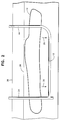
- Figure 1 is a top plan view of a contamination site having a plume of liquid contamination with a linear contaminated waste recovery system in place.
- Figure 2 is a sectional view of a linear contaminated waste recovery system in place having a horizontally extending drainage recovery pipe located below a plume of liquid contamination.
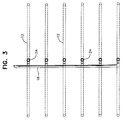
- Figure 3 is a plan view of a linear contaminated waste recovery system.
- Figure 4 is a partial sectional view of a horizontal well vertical header and riser.
- Figure 5 is a partial sectional view of a horizontal well flexible riser clean-out.
- Figure 6 is a sectional view of a linear contaminated waste recovery system with filtered liquid flushing system.
- Figure 7 is a sectional view of a linear contaminated waste recovery system and vapor recovery system.
- Figure 8 is a top plan view of the systems shown in Figure 7.
- Figure 9 is a perspective view of the systems shown in Figures 7 and 8.
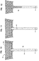
- FIGS 10 through 12 illustrate various trenching operations.
- a linear contaminated waste recovery system embodying the teachings of the subject invention is generally designated as 10.
- the containment system includes a plurality of buried horizontally extending drainage recovery pipes or horizontal well screen 12 which are located at or below the level of a buried plume of contaminated liquid 14.
- a former public works building 16 has, over the years, leaked fuel contaminant into the ground. These contaminants have collected and are a potential danger to the water supply.
- the recovery pipes 12 By burying the recovery pipes 12 below or at the level the plume 14 of liquid contamination, the water table is thereby lowered and the plume 14 is lowered into direct contact with the drainage recovery pipes 12 for evacuation from the water table.
- the recovery pipes 12 are connected to a suction header 16 which is above ground level.
- the suction header 16 is connected to the recovery pipes by a vertical riser 24 as shown in Figures 2, 4 and 5.
- the riser may actually rise vertically at an angle of from 30° to 90° dependent on the location of the pump, above or below ground, and the desired pumping volume.
- the suction header is connected by a transfer pipe 18 to an above ground pumping unit 20. It is not necessary that the pumping unit be located above ground, but rather the pumping unit may be of a below ground type as depicted in my U.S. Patent No. 4,927, 292.
- a discharge pipe 22 is connected to the pumping unit to convey the liquid withdrawn by the recovery pipes to a treatment facility. It is possible, as will be explained with reference to Figure 6 to return the treated liquid to the ground above the recovery pipes so as to use the treated liquid to help flush out the soil above the recovery pipes for evacuation of any remaining contaminants from the soil for treatment at a treatment facility.
- a recovery pipe 12 is shown connected to a vertical riser 24 which extends to above ground level 26 for removal of liquid below the upper surface 28 of the water table.
- the plume 14 of contaminated liquid is shown being located near the upper surface 28 of the water table.
- the contaminated liquid will be of a density less than water and will float to the upper surface of the water table.
- the level of the upper surface 28 of the water table and the plume 14 itself will be lowered as moved in the direction of arrows 30 and evacuated by the recovery pipe 12.
- a plurality of rows of recovery pipes 12, as shown in Figure 3 will be connected to their respective vertical risers 24 for connection to a suction header 16 and ultimate removal of contaminated liquid to a waste treatment facility.
- the recovery pipes extend for a distance of 600 feet (182.9 metre) and are spaced at 100 feet (30.48m) centers. The separation of the recovery pipes will depend upon the volume and the extent of spread of the plume 14 of contaminated liquid.
- FIG 4 the details of recovery of contaminated liquid from corrugated recovery pipe 12 are shown.
- the recovery pipe 12 surrounded by a filter cloth 32 is connected to an eight inch (20.3 cm) PVC vertical riser 24.
- Within the header 24 is a submersible pumping unit 34 having a surrounding seal 36.
- the pumping unit 34 is connected to a 3-inch (7.62cm) discharge pipe 36 and passes through a well head seal 38 in concrete seal 39 for connection with a suction header 16.
- Electric leads 40 pass through the well head seal to the pumping unit for energizing the pumping unit.
- the suction header 16 is a 4-inch (10.16cm) discharge pipe having a water meter 42 for measuring the amount of contaminated liquid extracted.
- a flexible riser 44 As shown in Figures 2 and 5.
- the flexible riser terminates at a concrete seal 46 having a six-inch (15.24cm) counter sunk plug 48 for access to the riser 44 and clean-out of the riser in the event the recovery pipe becomes clogged.
- recovery pipe 12 is located within plume 14 of contaminated liquid near the upper surface 28 of the water table. As the contaminated liquid of the plume 14 is gathered in the recovery pipes 12, it is pumped from the vertical riser 24 and ultimately to a waste treatment facility.
- the treated liquid is returned by return pipe 50 and spread over the soil by a plurality of vertical irrigation poles 52.
- Irrigation poles 52 include a sprinkler head 54 for distribution of the treated liquid over the soil.
- the treated liquid passing through the soil acts to flush the soil and move any contaminants that may be contained in the soil towards the recovery pipes 12 and its surrounding plume 14 of contaminated liquid.
- This "site dialysis” forces contaminants out of the soil and aids in removing the contaminants from the water table. This process is repeated until the level of contamination of the soil is reduced and of the plume 14 of contaminated liquid is removed.
- Flushing of the soil and removal of the plume is accomplished in a greatly reduced time period involving a substantially reduced amount of liquid to be treated. Therefore, once a site of liquid contamination is located, the horizontally extending recovery pipes 12 are located in place to draw down the water table and thereby encounter the plume of contaminated liquid to remove the plume.
- a vapor recovery or extraction system 60 is shown used in combination with a linear contaminated waste recovery system 10.
- System 60 includes a plurality of lengths of horizontally extending perforated pipe 62 spaced at a distance above the drainage recovery pipe 12 of system 10.
- Pipe 62 is positioned within the soil 63 above the water table.
- Pipe 62 is connected to a vertical riser 64 which is connected at a point 66 to an evacuation tube 68 for withdrawing air in the direction of arrow 70 as caused by a vacuum unit. Gases rising from the plume of contaminated liquid are forced into pipe 62 and removed from a site of contamination.
- FIG 8 the inter-lineation of pipes 62 of system 60 and pipes 12 of system 10 are shown.
- a header 72 is shown to which the plurality of pipes 64 are connected for evacuation through evacuation tube 68.
- Pipes 62 may also be used for a return of treated fluid to a site of a plume as described with respect to Figure 6 so as to rinse the soil and carry contaminants towards the recovery system 10 located adjacent to a plume of contaminated liquid.
- Each drainage recovery pipe 12 includes in a section of pipe 64 a flow meter A for measuring the rate of flow of product from recovery pipes 12 as controlled by an equalizing valve B.
- Dependent upon samples removed from a sampling port 76 it is determined to what extent contaminated product is being removed from a recovery site. If it is determined that a low level of contamination is being removed from a particular recovery pipe, its equalizing valve is varied to reduce the rate of flow as measured by flow meter A so as to reduce the amount of water being drawn from the water table through a particular recovery pipe.
- the equalizing valve is opened to increase the rate of flow of product and thereby increase the amount of contaminant removed.
- a length of pipe 78 includes an equalizing valve D and a manometer tap port E for each pipe section 62. Similar to recovery system 10, dependent upon the amount of gas removed by each pipe section 62, the amount of suction exerted on a particular pipe is varied by the turning of equalizing valve D as measured at the manometer tap port E.
- a benched area 80 of non-contaminated soil is removed over a 12-14 foot (3.65-4.26m) width to a depth dependent on a soil contamination survey to access non-contaminated soil.
- a trenching operation is performed through contaminated soil 82 at a width of approximately 14 inches (35.66cm) within which recovery pipe 12 is buried by back-filling contaminated soil within the trench 84.
- the non-contaminated soil 86 is then returned into the benched area 80 to seal the contaminated soil and prevent exposure of contamination to the trenching personnel.
Abstract
Description
- This invention is concerned with placing a horizontally extending grid system across a plume of liquid contamination contained within the water table. The grid system will remove the plume of contamination by lowering the water table and evacuating the contamination plume.
- Previous attempts to remove a plume of liquid contamination contained below ground have included placement of numerous vertical wells placed around the periphery of the plume. The vertical wells are operated continuously in an attempt to draw the liquid of a contamination plume towards the vertical well system. Great amounts of water are pumped out of the ground by these vertical wells at a great cost and over an extended period of time.
- These plumes of liquid are known to contain such dangerous substances as diesel fuel, jet fuel, gasoline, heating oil, creosote, and other chemicals, for example. Sources of contamination are thousands of aging underground tanks buried beneath schools, government offices, gasoline stations, businesses and abandoned property distributed throughout the United States. This problem has often times resulted in homeowners being forced from their homes due to condemning of their homes by public officials due to the extreme hazard and health risks involved.
- The presence of these contaminants in the water table present a continuous potential health hazard to the population. Rural and suburban residents who use wells for the source of their drinking water are particularly affected by this problem. It is estimated that half of the country relies on this type of source for their drinking water. The removal of these contaminates is therefore required to help ensure a potable water supply.
- In 1988, the Environmental Protection Agency (EPA) issued regulations requiring that new underground tanks meet minimum standards. Owners of older tanks were forced to close or upgrade their tanks. Since these regulations have been implemented, 130,000 leaks have been documented. Experts expect hundreds of thousands of more leaks to be discovered in the future. The new EPA rules have been estimated to apply to 1.8 million tanks nationwide. This number excludes millions of home heating oil, farm and other smaller underground tanks potentially subject to producing leaks.
- The US-A-4600508 describes a removal method for contaminated liquid using horizontal pipes.
- In accordance with the present invention, we provide a method for removing a plume of contaminated liquid from the water table, said method characterised by the steps of: locating a plume of contaminated liquid, positioning a plurality of rows of substantially horizontally extending perforated recovery pipes at a depth at least at or below the depth to which the plume of contaminated liquid extends, removing water from the water table to move the plume of contaminated liquid into contact with the recovery pipes, removing the plume of contaminated liquid from below ground level by passage through the recovery pipes as the plume moves into the recovery pipes, and positioning a vapour recovery system above the recovery pipes and below ground level to recover vapours generated by the plume including substantially horizontal pipes with open perforations.
- The drainage recovery pipes skim off the surface of the water table, along with the plume of contamination. This method minimizes the number of gallons of water that needs to be removed from the ground and cleaned.
- Once the contaminant is pumped from the ground, it is delivered to a conventional treatment system where it is cleaned and then the cleaned water is returned back to the ground water table. This cleaned water is reintroduced over the grid system of the invention and is drawn through the soil to flush out any remaining contaminants in the soil. Once the treated water reaches the water table, the liquid contaminants are usually less dense than water and rise towards the surface of the water table. The contaminants are then removed by the grid system for treatment.
- A plurality of horizontally extending drainage recovery pipes are located below the ground on (4.57 to 30.48m) 15 to 100 foot centers in or below the level of a plume of liquid contamination dependent on the volume and spread of the contamination. This depth of the horizontally extending drainage recovery pipes may vary from 8 to 30 feet (2.44 to 9.144m) below ground level and is dependent upon the variable height of the water table.
- The horizontally extending drainage pipes are used in cleanup efforts on contaminated sites, both for contaminated water and contaminate extraction. Aquifer recharge is obtained by using treated and/or processed water which is returned to the water table. The horizontally extending drainage recovery pipes are laid in a series of parallel trenches at or below the level of the plume of contamination. The trenches are dug by specialized equipment as described in my U.S. Patent No. 4,871,281.
- It is not required that personnel work in the excavated trenches for placement of the recovery pipes, thus reducing exposure to contaminants and other safety hazards. Also, the recovery pipes are locatable at the desired pumping points, even in saturated soils. This minimizes the need for off-site handling and disposal of contaminated free product and water which is extremely costly and hazardous.
- The drainage recovery pipe, including a filter casing, is placed along with filter sand in the trench and the trench is back-filled with the same soil removed to dig the trench. By the burial of the horizontally extended drainage recovery pipe at or below the site of contamination, ground water removal is minimized while containment recovery is maximized to thereby reduce waste water treatment volume and operational costs. As the water table is lowered, the plume of liquid contamination is lowered into direct contact with the drainage recovery pipes.
- By utilization of a soil benching installation method, the need to handle contaminated soils from the excavations, disposal, either on site or off-site, is minimized or eliminated. The project costs and hazardous exposure to personnel is thereby reduced.
- In the soil benching installation method, non-contaminated surface soils are excavated to depths of 3 - 6 feet (0.91 to 1.82m) and stored on site. The installation equipment is operated in the excavated or benched area to excavate contaminated soil. The excavated contaminated soils are deposited along the trench line in the bottom of the trenched area. After the recovery pipe installation is completed, the stored on-site, non-contaminated surface soils are replaced in and over the benched area.
- The grid system incorporating the horizontally extending drainage recovery pipe includes a plurality of lengths of pipe extending 600 linear feet (182.9 linear metres). The pipe is preferably six inch diameter high density polyethylene encased by a filter cloth. A central eight inch diameter PVC riser is located in the middle of each length of drainage pipe. At a location above ground, each of the vertical risers are interconnected by a suction header which transfers withdrawn water and contamination to a processing facility.
- The horizontal extending pipes have a clean-out/air relief vertically rising section at the outer ends of each 600 foot (182.9 metre) length of pipe. Therefore, there are two clean-out/air relief sections for each horizontal length of pipe. Access is thereby facilitated at both ends and a mid-point of the drainage recovery pipe for removal of contaminated liquid.
- It is possible to remove the upper level of the ground water table along with the harmful contamination plume by pumping out a plurality of horizontally extending drainage recovery pipes over a 24 hour period one time a week, for example. The actual pumping time will vary according to the extent of contamination and the proximity of the recovery pipes to the plume of contamination.
- All of the liquid removed is passed through a carbon filter system and is ultimately treated for removal of contaminants. The filtered liquid may be returned to the ground above the horizontal pipe drainage recovery system so that the liquid passes through the soil to the water table in a soil washing system which assists in the removal of contamination from contaminated soil. This is equivalent to a "site dialysis" which is used to continuously circulate liquid to flush contaminant from the water supply. The level of contamination is thereby significantly reduced to an acceptable level.
- This system can also be utilized as a vapor extraction process, either independently or in conjunction with a free product/water recovery system. Upper vapor recovery piping can be utilized as recharge points of treated water at an area directly over a contaminated plume area, thereby enhancing soils flushing and the area cleanup process. Additional air can be induced into the lower free product and water recovery pipes which allows enhancement of vaporization of the plume contaminants and vapor recovery by the upper system.
- Flow recovery rates of free product and water recovery are adjustable from time to time with balancing valves from individual recovery runs to minimize the circulation in the recovery/treatment cycle of low contaminated waters. This maximizes the recovery and treatment of higher contaminated waters.
- The site specific grid systems of the invention can include a perimeter recovery system around the plume. This can not only be utilized in the recovery treatment process, but can also serve as a plume containment installation.
- It is therefore an object of the present invention to provide a method of removing a plume of liquid contamination by reducing the level of the water table and thereby collect and remove the plume of liquid contamination.
- It is another object of the present invention to provide a method of removing a plume of liquid contamination by reducing the level of the water table and thereby collect and remove the plume of liquid contamination with a plurality of horizontally extending drainage recovery pipes located at or below the level of the plume of contamination.
- It is still another object of the present invention to provide a method of removing a plume of liquid contamination by reducing the level of the water table and thereby collect and remove the plume of liquid contamination with a plurality of horizontally extending drainage recovery pipes located at or below the level of the plume of contamination with the horizontally extending drainage recovery pipes having a vertical riser for removal of contaminated liquid and passage of the contaminated liquid to a filter system.
- It is still another of the present invention to provide a method of removing a plume of liquid contamination by reducing the level of the water table and thereby collect and remove the plume of liquid contamination with a plurality of horizontally extending drainage recovery pipes located at or below the level of the plume of contamination with the horizontally extending drainage recovery pipes having a vertical riser for removal of contaminated liquid and passage of the contaminated liquid to a filter system with the contaminated liquid being filtered and returned to the site of the horizontally extending drainage recovery pipes for passage through the soil above the drainage recovery pipes so as to flush contaminants from the soil and towards the drainage recovery pipes.
- These and other objects of the invention, as well as many of the intended advantages thereof, will become more readily apparent when reference is made to the following description taken in conjunction with the accompanying drawings.
- Figure 1 is a top plan view of a contamination site having a plume of liquid contamination with a linear contaminated waste recovery system in place.
- Figure 2 is a sectional view of a linear contaminated waste recovery system in place having a horizontally extending drainage recovery pipe located below a plume of liquid contamination.
- Figure 3 is a plan view of a linear contaminated waste recovery system.
- Figure 4 is a partial sectional view of a horizontal well vertical header and riser.
- Figure 5 is a partial sectional view of a horizontal well flexible riser clean-out.
- Figure 6 is a sectional view of a linear contaminated waste recovery system with filtered liquid flushing system.
- Figure 7 is a sectional view of a linear contaminated waste recovery system and vapor recovery system.
- Figure 8 is a top plan view of the systems shown in Figure 7.
- Figure 9 is a perspective view of the systems shown in Figures 7 and 8.
- Figures 10 through 12 illustrate various trenching operations.
- In describing a preferred embodiment of the invention illustrated in the drawings, specific terminology will be resorted to for the sake in clarity. However, the invention is not intended to be limited to the specific terms so selected, and it is to be understood that each specific term includes all technical equivalents which operate in a similar manner to accomplish a similar purpose.
- With reference to the drawings, in general, and to Figure 1 in particular, a linear contaminated waste recovery system embodying the teachings of the subject invention is generally designated as 10. The containment system includes a plurality of buried horizontally extending drainage recovery pipes or
horizontal well screen 12 which are located at or below the level of a buried plume of contaminatedliquid 14. - In this example, a former public works building 16 has, over the years, leaked fuel contaminant into the ground. These contaminants have collected and are a potential danger to the water supply. By burying the
recovery pipes 12 below or at the level theplume 14 of liquid contamination, the water table is thereby lowered and theplume 14 is lowered into direct contact with thedrainage recovery pipes 12 for evacuation from the water table. - The
recovery pipes 12 are connected to asuction header 16 which is above ground level. Thesuction header 16 is connected to the recovery pipes by avertical riser 24 as shown in Figures 2, 4 and 5. The riser may actually rise vertically at an angle of from 30° to 90° dependent on the location of the pump, above or below ground, and the desired pumping volume. - The suction header is connected by a
transfer pipe 18 to an aboveground pumping unit 20. It is not necessary that the pumping unit be located above ground, but rather the pumping unit may be of a below ground type as depicted in my U.S. Patent No. 4,927, 292. - A
discharge pipe 22 is connected to the pumping unit to convey the liquid withdrawn by the recovery pipes to a treatment facility. It is possible, as will be explained with reference to Figure 6 to return the treated liquid to the ground above the recovery pipes so as to use the treated liquid to help flush out the soil above the recovery pipes for evacuation of any remaining contaminants from the soil for treatment at a treatment facility. - In Figure 2, a
recovery pipe 12 is shown connected to avertical riser 24 which extends to aboveground level 26 for removal of liquid below theupper surface 28 of the water table. Theplume 14 of contaminated liquid is shown being located near theupper surface 28 of the water table. Typically, the contaminated liquid will be of a density less than water and will float to the upper surface of the water table. As the water table is lowered by water enteringrecovery pipes 12 and evacuation of the contaminated liquid throughvertical riser 24, the level of theupper surface 28 of the water table and theplume 14 itself, will be lowered as moved in the direction ofarrows 30 and evacuated by therecovery pipe 12. - Typically, a plurality of rows of
recovery pipes 12, as shown in Figure 3, will be connected to their respectivevertical risers 24 for connection to asuction header 16 and ultimate removal of contaminated liquid to a waste treatment facility. In the example shown, the recovery pipes extend for a distance of 600 feet (182.9 metre) and are spaced at 100 feet (30.48m) centers. The separation of the recovery pipes will depend upon the volume and the extent of spread of theplume 14 of contaminated liquid. - In Figure 4, the details of recovery of contaminated liquid from
corrugated recovery pipe 12 are shown. Therecovery pipe 12 surrounded by afilter cloth 32 is connected to an eight inch (20.3 cm) PVCvertical riser 24. Within theheader 24 is asubmersible pumping unit 34 having a surroundingseal 36. Thepumping unit 34 is connected to a 3-inch (7.62cm)discharge pipe 36 and passes through awell head seal 38 inconcrete seal 39 for connection with asuction header 16. Electric leads 40 pass through the well head seal to the pumping unit for energizing the pumping unit. Thesuction header 16 is a 4-inch (10.16cm) discharge pipe having awater meter 42 for measuring the amount of contaminated liquid extracted. - At the opposite end of the
recovery pipe 12 from thevertical header 24 is aflexible riser 44 as shown in Figures 2 and 5. The flexible riser terminates at aconcrete seal 46 having a six-inch (15.24cm) counter sunkplug 48 for access to theriser 44 and clean-out of the riser in the event the recovery pipe becomes clogged. - In a preferred embodiment as shown in Figure 6,
recovery pipe 12 is located withinplume 14 of contaminated liquid near theupper surface 28 of the water table. As the contaminated liquid of theplume 14 is gathered in therecovery pipes 12, it is pumped from thevertical riser 24 and ultimately to a waste treatment facility. - The treated liquid is returned by
return pipe 50 and spread over the soil by a plurality ofvertical irrigation poles 52.Irrigation poles 52 include asprinkler head 54 for distribution of the treated liquid over the soil. The treated liquid passing through the soil acts to flush the soil and move any contaminants that may be contained in the soil towards therecovery pipes 12 and its surroundingplume 14 of contaminated liquid. This "site dialysis" forces contaminants out of the soil and aids in removing the contaminants from the water table. This process is repeated until the level of contamination of the soil is reduced and of theplume 14 of contaminated liquid is removed. - Flushing of the soil and removal of the plume is accomplished in a greatly reduced time period involving a substantially reduced amount of liquid to be treated. Therefore, once a site of liquid contamination is located, the horizontally extending
recovery pipes 12 are located in place to draw down the water table and thereby encounter the plume of contaminated liquid to remove the plume. - In Figures 7 through 9, a vapor recovery or
extraction system 60 is shown used in combination with a linear contaminatedwaste recovery system 10.System 60 includes a plurality of lengths of horizontally extendingperforated pipe 62 spaced at a distance above thedrainage recovery pipe 12 ofsystem 10.Pipe 62 is positioned within thesoil 63 above the water table. -
Pipe 62 is connected to avertical riser 64 which is connected at apoint 66 to anevacuation tube 68 for withdrawing air in the direction ofarrow 70 as caused by a vacuum unit. Gases rising from the plume of contaminated liquid are forced intopipe 62 and removed from a site of contamination. - In Figure 8, the inter-lineation of
pipes 62 ofsystem 60 andpipes 12 ofsystem 10 are shown. In Figure 8, aheader 72 is shown to which the plurality ofpipes 64 are connected for evacuation throughevacuation tube 68.Pipes 62 may also be used for a return of treated fluid to a site of a plume as described with respect to Figure 6 so as to rinse the soil and carry contaminants towards therecovery system 10 located adjacent to a plume of contaminated liquid. - In Figure 9, additional details of the
systems drainage recovery pipe 12 includes in a section of pipe 64 a flow meter A for measuring the rate of flow of product fromrecovery pipes 12 as controlled by an equalizing valve B. Dependent upon samples removed from asampling port 76, it is determined to what extent contaminated product is being removed from a recovery site. If it is determined that a low level of contamination is being removed from a particular recovery pipe, its equalizing valve is varied to reduce the rate of flow as measured by flow meter A so as to reduce the amount of water being drawn from the water table through a particular recovery pipe. Conversely, in therecovery pipes 12 measuring a high degree of contaminant in the product removed from the recovery pipe, the equalizing valve is opened to increase the rate of flow of product and thereby increase the amount of contaminant removed. - In the
vapor recovery system 60, a length ofpipe 78 includes an equalizing valve D and a manometer tap port E for eachpipe section 62. Similar torecovery system 10, dependent upon the amount of gas removed by eachpipe section 62, the amount of suction exerted on a particular pipe is varied by the turning of equalizing valve D as measured at the manometer tap port E. - In Figures 10 and 11, a benched
area 80 of non-contaminated soil is removed over a 12-14 foot (3.65-4.26m) width to a depth dependent on a soil contamination survey to access non-contaminated soil. After initiating removal of the benched area, a trenching operation is performed through contaminated soil 82 at a width of approximately 14 inches (35.66cm) within whichrecovery pipe 12 is buried by back-filling contaminated soil within thetrench 84. Thenon-contaminated soil 86 is then returned into the benchedarea 80 to seal the contaminated soil and prevent exposure of contamination to the trenching personnel. - In Figure 11, a similar operation is performed with burial of a
vapor recovery pipe 62. This is contrasted to the trenching of non-contaminated soil as shown in Figure 12 for burial of anyrecovery pipe 12.
Claims (9)
- A method for removing a plume (14) of contaminated liquid from the water table, said method comprising the steps of:locating a plume of contaminated liquid,positioning a plurality of rows of substantially horizontally extending perforated recovery pipes (12) at a depth at least at or below the depth to which the plume (14) of contaminated liquid extends,removing water from the water table to move the plume (14) of contaminated liquid into contact with the recovery pipes,removing the plume (14) of contaminated liquid from below ground level by passage through the recovery pipes (12) as the plume (14) moves into the recovery pipes, and being characterized bypositioning a vapour recovery system (60) above the recovery pipes (12) and below ground level to recover vapours generated by the plume (14) including substantially horizontal pipes (62) with open perforations.
- A method according to claim 1, wherein said recovery pipes are positioned below the plume (14) of contaminated liquid.
- A method according to claim 1, wherein a pumping unit (20) forces liquid entering the recovery pipes (12) to an above ground location; and wherein a treatment facility treats water entered into the recovery pipes (12).
- A method according to claim 3, wherein the treatment facility is located above ground level.
- A method according to claim 3, wherein water treated by the treatment facility is returned to the site of the plume (14) of contaminated liquid for release above the site of the plume (14) of contaminated liquid so as to pass through the soil towards the site of the plume (14) of contaminated liquid.
- A method according to claim 5, wherein water treated by the treatment facility, after passing through the soil, is removed by the recovery pipes (12) for a second treatment at the treatment facility.
- A method according to claim 1, wherein the recovery pipes (12) are positioned to extend across, and are buried below, the plume (14) of contaminated liquid.
- A method according to claim 1, wherein a volume of flow through the recovery pipes (12) is variable dependent upon the degree of contamination passing through each recovery pipe (12).
- A method according to claim 1, wherein the recovery pipes (12) extend parallel to each other, and are substantially horizontal.
Applications Claiming Priority (3)
| Application Number | Priority Date | Filing Date | Title |
|---|---|---|---|
| US882228 | 1992-05-13 | ||
| US07/882,228 US5252226A (en) | 1992-05-13 | 1992-05-13 | Linear contaminate remediation system |
| PCT/US1993/004376 WO1993023134A1 (en) | 1992-05-13 | 1993-05-13 | Linear contaminant remediation system |
Publications (3)
| Publication Number | Publication Date |
|---|---|
| EP0640001A1 EP0640001A1 (en) | 1995-03-01 |
| EP0640001A4 EP0640001A4 (en) | 1996-05-15 |
| EP0640001B1 true EP0640001B1 (en) | 1997-08-06 |
Family
ID=25380166
Family Applications (1)
| Application Number | Title | Priority Date | Filing Date |
|---|---|---|---|
| EP93911177A Expired - Lifetime EP0640001B1 (en) | 1992-05-13 | 1993-05-13 | Linear contaminant remediation process |
Country Status (7)
| Country | Link |
|---|---|
| US (1) | US5252226A (en) |
| EP (1) | EP0640001B1 (en) |
| AT (1) | ATE156379T1 (en) |
| AU (1) | AU674319B2 (en) |
| DE (1) | DE69312934T2 (en) |
| NZ (1) | NZ252566A (en) |
| WO (1) | WO1993023134A1 (en) |
Families Citing this family (29)
| Publication number | Priority date | Publication date | Assignee | Title |
|---|---|---|---|---|
| US5348422A (en) * | 1993-02-25 | 1994-09-20 | Terranalysis Corporation | Methods for the formation and operation of an in situ process reactor |
| US5385677A (en) * | 1993-04-30 | 1995-01-31 | Venable; William B. | Fiber optic photochemical oxidation decontamination of aqueous leachate plumes |
| US5591115A (en) * | 1994-01-12 | 1997-01-07 | K & M Engineering & Consulting Corp. | Barrier for blocking movement of contaminants within an aggregate particulate substrate |
| US5639380A (en) * | 1994-05-31 | 1997-06-17 | Misquitta; Neale J. | System for automating groundwater recovery controlled by monitoring parameters in monitoring wells |
| GB9412997D0 (en) * | 1994-06-28 | 1994-08-17 | Pelletier Marc Antoine | Method of decontaminating soils in situ combining horizontal radial flow technique and depolluting agents in a confined site |
| US5605417A (en) * | 1994-07-18 | 1997-02-25 | The Dragun Corporation | Method and apparatus for improving degradation of an unsecured landfill |
| US5685668A (en) * | 1994-09-07 | 1997-11-11 | Justice; Donald R. | Barrier wall installation system |
| US5584605A (en) * | 1995-06-29 | 1996-12-17 | Beard; Barry C. | Enhanced in situ hydrocarbon removal from soil and groundwater |
| US5676207A (en) * | 1996-05-20 | 1997-10-14 | Simon; Philip B. | Soil vapor extraction system |
| AR008222A1 (en) * | 1996-05-30 | 1999-12-29 | Hwang Daekyoo | METHOD FOR CONTAINING AND RECOVERING LEACHING FROM A WASTE MANAGEMENT DISPOSAL IN A WASTE MANAGEMENT AREA, AND WASTE MANAGEMENT DISPOSAL |
| US5771976A (en) * | 1996-06-19 | 1998-06-30 | Talley; Robert R. | Enhanced production rate water well system |
| US5957665A (en) * | 1997-05-19 | 1999-09-28 | Reichhold Chemicals Inc. | Jet system total fluids recovery system |
| CA2252341A1 (en) * | 1997-11-03 | 1999-05-03 | Mcgill University | Method and apparatus for remediation of contaminated soil |
| US6422318B1 (en) * | 1999-12-17 | 2002-07-23 | Scioto County Regional Water District #1 | Horizontal well system |
| US7809538B2 (en) | 2006-01-13 | 2010-10-05 | Halliburton Energy Services, Inc. | Real time monitoring and control of thermal recovery operations for heavy oil reservoirs |
| US7832482B2 (en) | 2006-10-10 | 2010-11-16 | Halliburton Energy Services, Inc. | Producing resources using steam injection |
| US7770643B2 (en) | 2006-10-10 | 2010-08-10 | Halliburton Energy Services, Inc. | Hydrocarbon recovery using fluids |
| US7909094B2 (en) | 2007-07-06 | 2011-03-22 | Halliburton Energy Services, Inc. | Oscillating fluid flow in a wellbore |
| JP2010119916A (en) * | 2008-11-17 | 2010-06-03 | Kumagai Gumi Co Ltd | Oil recovery method of oil contaminated soil |
| US7862713B2 (en) * | 2009-03-24 | 2011-01-04 | Donald Justice | Reservoir water filtration system |
| US20120009015A1 (en) * | 2010-07-06 | 2012-01-12 | Donald Justice | Beach preservation system |
| CN102080530B (en) * | 2010-12-22 | 2013-05-22 | 北京奥瑞安能源技术开发有限公司 | Method for constructing horizontal coal bed gas well and vertical drainage and mining well |
| CA2972203C (en) | 2017-06-29 | 2018-07-17 | Exxonmobil Upstream Research Company | Chasing solvent for enhanced recovery processes |
| CA2974712C (en) | 2017-07-27 | 2018-09-25 | Imperial Oil Resources Limited | Enhanced methods for recovering viscous hydrocarbons from a subterranean formation as a follow-up to thermal recovery processes |
| CA2978157C (en) | 2017-08-31 | 2018-10-16 | Exxonmobil Upstream Research Company | Thermal recovery methods for recovering viscous hydrocarbons from a subterranean formation |
| CA2983541C (en) | 2017-10-24 | 2019-01-22 | Exxonmobil Upstream Research Company | Systems and methods for dynamic liquid level monitoring and control |
| EP3731980A1 (en) * | 2017-12-26 | 2020-11-04 | Earth Purified LLC | System and method for reclaiming and optimizing land |
| JP7296903B2 (en) * | 2020-02-27 | 2023-06-23 | 鹿島建設株式会社 | Methods of constructing fluid recovery systems and structures |
| CN113385526A (en) * | 2021-03-11 | 2021-09-14 | 江苏大地益源环境修复有限公司 | Horizontal well injection repairing method and device for shallow organic pollution site |
Family Cites Families (8)
| Publication number | Priority date | Publication date | Assignee | Title |
|---|---|---|---|---|
| US3425555A (en) * | 1966-11-25 | 1969-02-04 | Union Oil Co | Process for recovery of contaminants from the ground |
| US4435292A (en) * | 1980-01-28 | 1984-03-06 | Kbi Corp. | Portable method for decontaminating earth |
| US4600508A (en) * | 1984-02-21 | 1986-07-15 | Foster Wheeler Energy Corporation | Contamination removal system |
| US4895085A (en) * | 1988-01-11 | 1990-01-23 | Chips Mark D | Method and structure for in-situ removal of contamination from soils and water |
| US4871281A (en) * | 1988-02-28 | 1989-10-03 | Justice Donald R | Trenching tool for installing perforated pipe |
| WO1991003280A1 (en) * | 1989-08-31 | 1991-03-21 | Dames & Moore Pty. Ltd. | Apparatus for removing volatile contaminants from soil |
| DE4040838C2 (en) * | 1990-01-12 | 1998-09-17 | Messer Griesheim Gmbh | Process for removing volatile pollutants from soils and groundwater |
| US5118230A (en) * | 1990-12-27 | 1992-06-02 | Justice Donald R | Method and apparatus for installation of leachate containment system |
-
1992
- 1992-05-13 US US07/882,228 patent/US5252226A/en not_active Expired - Fee Related
-
1993
- 1993-05-13 AU AU42407/93A patent/AU674319B2/en not_active Ceased
- 1993-05-13 EP EP93911177A patent/EP0640001B1/en not_active Expired - Lifetime
- 1993-05-13 AT AT93911177T patent/ATE156379T1/en active
- 1993-05-13 NZ NZ252566A patent/NZ252566A/en unknown
- 1993-05-13 WO PCT/US1993/004376 patent/WO1993023134A1/en active IP Right Grant
- 1993-05-13 DE DE69312934T patent/DE69312934T2/en not_active Expired - Fee Related
Also Published As
| Publication number | Publication date |
|---|---|
| DE69312934T2 (en) | 1998-01-29 |
| EP0640001A1 (en) | 1995-03-01 |
| US5252226A (en) | 1993-10-12 |
| AU674319B2 (en) | 1996-12-19 |
| NZ252566A (en) | 1998-04-27 |
| EP0640001A4 (en) | 1996-05-15 |
| DE69312934D1 (en) | 1997-09-11 |
| WO1993023134A1 (en) | 1993-11-25 |
| AU4240793A (en) | 1993-12-13 |
| ATE156379T1 (en) | 1997-08-15 |
Similar Documents
| Publication | Publication Date | Title |
|---|---|---|
| EP0640001B1 (en) | Linear contaminant remediation process | |
| WO1993023134A9 (en) | Linear contaminant remediation system | |
| US4582611A (en) | Soil decontamination with wick drains | |
| CN108314106B (en) | DNAPL (deoxyribonucleic acid-styrene-acrylonitrile copolymer) polluted underground water in-situ remediation method | |
| US5161914A (en) | Slotted extraction trench remediation system | |
| US5120160A (en) | Method and apparatus for confining and reclaiming hydrocarbon contaminated land sites | |
| CN104043644B (en) | A kind of layered circulation that utilizes cleans the method for administering soil pollution | |
| US11041298B2 (en) | Trenchlessly installed subterranean collector drain for surface and subsurface water | |
| US5054961A (en) | Onsite soil treatment process | |
| US3425555A (en) | Process for recovery of contaminants from the ground | |
| Cohen et al. | Design guidelines for conventional pump-and-treat systems | |
| WO2023147543A1 (en) | Systems and methods for underground storage of storm and other water sources | |
| US7374691B2 (en) | In-situ hydraulic treatment conduit | |
| US6139221A (en) | Constant hydraulic head moat and method for controlling regional ground water flow | |
| CN113753981A (en) | Fourth series underground water and soil pollution treatment method | |
| RU134950U1 (en) | MOBILE DRAINAGE PLANT FOR THE RECULTIVATION OF SALTED SOILS | |
| CN109467143B (en) | Shallow groundwater extraction and restoration treatment system and method | |
| RU2047542C1 (en) | Method of gathering oil products from contaminated water-bearing beds and hydrogeodynamic trap for oil products | |
| CN218961836U (en) | Efficient deep DNAPL polluted groundwater extraction device | |
| JPS61178086A (en) | Method for embedding treatment of waste | |
| US6979150B1 (en) | In-situ containment and extraction of volatile soil contaminants | |
| CN212792389U (en) | A restoration well for driving soil and groundwater pollution | |
| RU2792986C1 (en) | Method for cleaning oil-contaminated surface soil | |
| CA2171833A1 (en) | Method and device for detecting soil pollution or cleaning up polluted soil in situ, respectively | |
| CN107082474A (en) | Leakage oil pollution soil and the quick repair system of underground water based on electric flocculation technique |
Legal Events
| Date | Code | Title | Description |
|---|---|---|---|
| PUAI | Public reference made under article 153(3) epc to a published international application that has entered the european phase |
Free format text: ORIGINAL CODE: 0009012 |
|
| 17P | Request for examination filed |
Effective date: 19941213 |
|
| AK | Designated contracting states |
Kind code of ref document: A1 Designated state(s): AT BE CH DE DK ES FR GB GR IE IT LI LU MC NL PT SE |
|
| A4 | Supplementary search report drawn up and despatched |
Effective date: 19960326 |
|
| AK | Designated contracting states |
Kind code of ref document: A4 Designated state(s): AT BE CH DE DK ES FR GB GR IE IT LI LU MC NL PT SE |
|
| 17Q | First examination report despatched |
Effective date: 19960730 |
|
| GRAG | Despatch of communication of intention to grant |
Free format text: ORIGINAL CODE: EPIDOS AGRA |
|
| GRAH | Despatch of communication of intention to grant a patent |
Free format text: ORIGINAL CODE: EPIDOS IGRA |
|
| GRAH | Despatch of communication of intention to grant a patent |
Free format text: ORIGINAL CODE: EPIDOS IGRA |
|
| GRAA | (expected) grant |
Free format text: ORIGINAL CODE: 0009210 |
|
| AK | Designated contracting states |
Kind code of ref document: B1 Designated state(s): AT BE CH DE DK ES FR GB GR IE IT LI LU MC NL PT SE |
|
| PG25 | Lapsed in a contracting state [announced via postgrant information from national office to epo] |
Ref country code: NL Free format text: LAPSE BECAUSE OF FAILURE TO SUBMIT A TRANSLATION OF THE DESCRIPTION OR TO PAY THE FEE WITHIN THE PRESCRIBED TIME-LIMIT Effective date: 19970806 Ref country code: LI Free format text: LAPSE BECAUSE OF FAILURE TO SUBMIT A TRANSLATION OF THE DESCRIPTION OR TO PAY THE FEE WITHIN THE PRESCRIBED TIME-LIMIT Effective date: 19970806 Ref country code: GR Free format text: LAPSE BECAUSE OF FAILURE TO SUBMIT A TRANSLATION OF THE DESCRIPTION OR TO PAY THE FEE WITHIN THE PRESCRIBED TIME-LIMIT Effective date: 19970806 Ref country code: ES Free format text: THE PATENT HAS BEEN ANNULLED BY A DECISION OF A NATIONAL AUTHORITY Effective date: 19970806 Ref country code: DK Free format text: LAPSE BECAUSE OF NON-PAYMENT OF DUE FEES Effective date: 19970806 Ref country code: CH Free format text: LAPSE BECAUSE OF FAILURE TO SUBMIT A TRANSLATION OF THE DESCRIPTION OR TO PAY THE FEE WITHIN THE PRESCRIBED TIME-LIMIT Effective date: 19970806 Ref country code: AT Effective date: 19970806 |
|
| REF | Corresponds to: |
Ref document number: 156379 Country of ref document: AT Date of ref document: 19970815 Kind code of ref document: T |
|
| REG | Reference to a national code |
Ref country code: CH Ref legal event code: EP |
|
| REF | Corresponds to: |
Ref document number: 69312934 Country of ref document: DE Date of ref document: 19970911 |
|
| ITF | It: translation for a ep patent filed |
Owner name: INTERPATENT ST.TECN. BREV. |
|
| PG25 | Lapsed in a contracting state [announced via postgrant information from national office to epo] |
Ref country code: SE Effective date: 19971106 |
|
| PG25 | Lapsed in a contracting state [announced via postgrant information from national office to epo] |
Ref country code: PT Effective date: 19971112 |
|
| ET | Fr: translation filed | ||
| NLV1 | Nl: lapsed or annulled due to failure to fulfill the requirements of art. 29p and 29m of the patents act | ||
| REG | Reference to a national code |
Ref country code: CH Ref legal event code: PL |
|
| PG25 | Lapsed in a contracting state [announced via postgrant information from national office to epo] |
Ref country code: LU Free format text: LAPSE BECAUSE OF NON-PAYMENT OF DUE FEES Effective date: 19980513 |
|
| PLBE | No opposition filed within time limit |
Free format text: ORIGINAL CODE: 0009261 |
|
| STAA | Information on the status of an ep patent application or granted ep patent |
Free format text: STATUS: NO OPPOSITION FILED WITHIN TIME LIMIT |
|
| 26N | No opposition filed | ||
| PG25 | Lapsed in a contracting state [announced via postgrant information from national office to epo] |
Ref country code: MC Free format text: LAPSE BECAUSE OF NON-PAYMENT OF DUE FEES Effective date: 19981130 |
|
| PGFP | Annual fee paid to national office [announced via postgrant information from national office to epo] |
Ref country code: GB Payment date: 20000508 Year of fee payment: 8 |
|
| PGFP | Annual fee paid to national office [announced via postgrant information from national office to epo] |
Ref country code: IE Payment date: 20000517 Year of fee payment: 8 |
|
| PGFP | Annual fee paid to national office [announced via postgrant information from national office to epo] |
Ref country code: FR Payment date: 20000525 Year of fee payment: 8 |
|
| PGFP | Annual fee paid to national office [announced via postgrant information from national office to epo] |
Ref country code: BE Payment date: 20000526 Year of fee payment: 8 |
|
| PGFP | Annual fee paid to national office [announced via postgrant information from national office to epo] |
Ref country code: DE Payment date: 20000728 Year of fee payment: 8 |
|
| PG25 | Lapsed in a contracting state [announced via postgrant information from national office to epo] |
Ref country code: GB Free format text: LAPSE BECAUSE OF NON-PAYMENT OF DUE FEES Effective date: 20010513 |
|
| PG25 | Lapsed in a contracting state [announced via postgrant information from national office to epo] |
Ref country code: IE Free format text: LAPSE BECAUSE OF NON-PAYMENT OF DUE FEES Effective date: 20010514 |
|
| PG25 | Lapsed in a contracting state [announced via postgrant information from national office to epo] |
Ref country code: BE Free format text: LAPSE BECAUSE OF NON-PAYMENT OF DUE FEES Effective date: 20010531 |
|
| BERE | Be: lapsed |
Owner name: JUSTICE DONALD R. Effective date: 20010531 |
|
| GBPC | Gb: european patent ceased through non-payment of renewal fee |
Effective date: 20010513 |
|
| PG25 | Lapsed in a contracting state [announced via postgrant information from national office to epo] |
Ref country code: FR Free format text: LAPSE BECAUSE OF NON-PAYMENT OF DUE FEES Effective date: 20020131 |
|
| PG25 | Lapsed in a contracting state [announced via postgrant information from national office to epo] |
Ref country code: DE Free format text: LAPSE BECAUSE OF NON-PAYMENT OF DUE FEES Effective date: 20020301 |
|
| REG | Reference to a national code |
Ref country code: IE Ref legal event code: MM4A |
|
| PG25 | Lapsed in a contracting state [announced via postgrant information from national office to epo] |
Ref country code: IT Free format text: LAPSE BECAUSE OF NON-PAYMENT OF DUE FEES;WARNING: LAPSES OF ITALIAN PATENTS WITH EFFECTIVE DATE BEFORE 2007 MAY HAVE OCCURRED AT ANY TIME BEFORE 2007. THE CORRECT EFFECTIVE DATE MAY BE DIFFERENT FROM THE ONE RECORDED. Effective date: 20050513 |