EP0639692B1 - Mechanical damper - Google Patents
Mechanical damper Download PDFInfo
- Publication number
- EP0639692B1 EP0639692B1 EP94302982A EP94302982A EP0639692B1 EP 0639692 B1 EP0639692 B1 EP 0639692B1 EP 94302982 A EP94302982 A EP 94302982A EP 94302982 A EP94302982 A EP 94302982A EP 0639692 B1 EP0639692 B1 EP 0639692B1
- Authority
- EP
- European Patent Office
- Prior art keywords
- segmented
- stator
- shaped
- inner shroud
- annular
- Prior art date
- Legal status (The legal status is an assumption and is not a legal conclusion. Google has not performed a legal analysis and makes no representation as to the accuracy of the status listed.)
- Expired - Lifetime
Links
- 239000000463 material Substances 0.000 claims description 4
- 239000012530 fluid Substances 0.000 claims description 2
- 230000000295 complement effect Effects 0.000 claims 1
- 238000013016 damping Methods 0.000 description 10
- 230000000717 retained effect Effects 0.000 description 2
- 238000009825 accumulation Methods 0.000 description 1
- 230000006378 damage Effects 0.000 description 1
- 230000007257 malfunction Effects 0.000 description 1
- 239000002184 metal Substances 0.000 description 1
Images
Classifications
-
- F—MECHANICAL ENGINEERING; LIGHTING; HEATING; WEAPONS; BLASTING
- F01—MACHINES OR ENGINES IN GENERAL; ENGINE PLANTS IN GENERAL; STEAM ENGINES
- F01D—NON-POSITIVE DISPLACEMENT MACHINES OR ENGINES, e.g. STEAM TURBINES
- F01D11/00—Preventing or minimising internal leakage of working-fluid, e.g. between stages
- F01D11/08—Preventing or minimising internal leakage of working-fluid, e.g. between stages for sealing space between rotor blade tips and stator
- F01D11/12—Preventing or minimising internal leakage of working-fluid, e.g. between stages for sealing space between rotor blade tips and stator using a rubstrip, e.g. erodible. deformable or resiliently-biased part
- F01D11/127—Preventing or minimising internal leakage of working-fluid, e.g. between stages for sealing space between rotor blade tips and stator using a rubstrip, e.g. erodible. deformable or resiliently-biased part with a deformable or crushable structure, e.g. honeycomb
-
- F—MECHANICAL ENGINEERING; LIGHTING; HEATING; WEAPONS; BLASTING
- F01—MACHINES OR ENGINES IN GENERAL; ENGINE PLANTS IN GENERAL; STEAM ENGINES
- F01D—NON-POSITIVE DISPLACEMENT MACHINES OR ENGINES, e.g. STEAM TURBINES
- F01D11/00—Preventing or minimising internal leakage of working-fluid, e.g. between stages
- F01D11/005—Sealing means between non relatively rotating elements
-
- F—MECHANICAL ENGINEERING; LIGHTING; HEATING; WEAPONS; BLASTING
- F01—MACHINES OR ENGINES IN GENERAL; ENGINE PLANTS IN GENERAL; STEAM ENGINES
- F01D—NON-POSITIVE DISPLACEMENT MACHINES OR ENGINES, e.g. STEAM TURBINES
- F01D25/00—Component parts, details, or accessories, not provided for in, or of interest apart from, other groups
- F01D25/04—Antivibration arrangements
Definitions
- This invention relates to mechanical spring-type dampers and particularly to means for damping cast stators used e.g. on compressors for gas turbine engines.
- stator vanes and shrouds are inherently not capable of providing damping.
- the compressor stators and particularly the stators used on the high pressure compressor have proven to be likely candidates where cast parts can be utilized.
- cast stator vanes and shrouds inherently do not have damping capabilities in comparison with other similar fabricated designs, the lack of damping has been a major obstacle standing in the way of utilizing cast parts.
- damping is essential. Damping is not only necessary to withstand the exceedingly high vibratory stresses incidental in aircraft operation, it must also keep the parts out of resonance to assure their adequate life. It is therefore imperative that damping be incorporated in cast parts in order to attain the desired structural integrity needed in this environment.
- this invention contemplates a mechanical spring-like damper that is capable of providing sufficient loading required for damping the vibratory energy existing in this hostile environment and being sufficiently small to be able to fit into the limited space of the available envelope of a high pressure compressor stator of a gas turbine engine.
- GB-2219355 discloses using a resilient spring member as a damper which is slidable on an inner air seal and/or a stator vane.
- An object of this invention is to provide a damper for a cast stator for a gas turbine engine.
- a feature of this invention is to provide a spring-like damper that is fabricated from a highly resilient, flexible preferably metallic spring material which is shaped in the form of an "E" in cross-section.
- Another feature of this invention is to provide an annular E-shaped spring damper (either segmented or continuous) that is sufficiently small to fit into a cavity located on the inside diameter of the shroud of the stator and retained by the honeycomb ring segments circumferentially disposed about the stator.
- the stator section generally illustrated by reference numeral 10 comprises three (3) rows of vanes 12, 14, and 16 supported to the annular segmented outer shrouds 18, 20 and 22 respectively.
- An inner shroud 24, 26 and 28 respectively supports the inner diameter of the vanes 12, 14 and 16, respectively.
- Supported to the inner diameter of the inner shrouds 24, 26 and 28 are the annular honeycomb segments 30, 32 and 34, respectively that form the labyrinth seal used to seal the fluid medium in the gas path defined between the inner shrouds 24, 26, and 28 and the outer shrouds 18, 20 and 22.
- a portion of the drum rotor 36 that carries the compressor rotor blades (not shown) that are rotary mounted to extend adjacent to the respective vanes and to receive the engine working medium to be compressed is shown to illustrate the teeth 38 of the labyrinth seal and how it cooperates with the respective honeycomb segments.
- this invention is only concerned with the damper aspects of the compressor stator, for the sake of convenience and simplicity the details of the compressor and gas turbine engine are omitted herefrom. For further details reference should be made to U. S. Patent Number 5,127,794.
- the segmented back rings 40, 42 and 44 of the honeycomb segments serve to attach the honeycomb to the depending flanges 46 and 48, 50 and 52, and 54 and 56, respectively.
- Each of the segmented back rings 40, 42 and 44 are bent to define a U-shaped channel to allow the respective flanges to slide into them.
- Pins 58, 60 and 62, respectively, serve to secure the honeycomb elements to the inner shrouds 24, 26 and 28 in a well known manner.
- a cavity is formed between the end flange and the depending member.
- This invention has been able to capitalize on this envelope and utilize this cavity, notwithstanding the fact that in actuality this area provides very little space.
- a judiciously shaped damper is discretely located so as to provide sufficient frictional damping to attenuate the frequencies encountered in this environment.
- dampers 70, 72 and 74 are formed from spring material, e.g. relatively thin metal spring stock, into E-shaped segments in cross-section that are fitted and compressed into cavities 76, 78 and 80 respectively.
- Each damper has a pair of end legs at its opposite ends, and between the end legs it is bent to form three generally parallel lobes giving it generally an E-shaped appearance. If the cross-section is regarded as a repeating wave shape, then there are 21 ⁇ 2 complete waves.
- Each segment is bent into an arcuate shaped segment to define the annular shape to conform to the annular cavity formed on the inner diameter of the inner shrouds 24, 26 and 28.
- the end legs of the E-shaped damper bear against the inner surface of the respective flange and the radial extending portion of the honeycomb ring back segment that bears against the depending flange (64, 66, 68) and defines the cavity, and are compressed into the cavity of the stator.
- Each end leg of the damper is bent back slightly away from the end of the damper to produce a convex outer contact surface which contacts the respective flange essentially along a line. It is retained in that location by the respective inner shrouds and honeycomb ring segments which slide circumferentially around the stator.
- the E-shaped damper is relatively simple to make and is effective to work in confined spaces and hence requires a minimum of space. As noted above, since it is flexible in its design, as one skilled in this art will appreciate, it has potential for being utilized for other applications. Because of its shape, the spring damper has a large load variation available which makes it efficacious in the hostile environment encountered in gas turbine engines. Of noteworthiness is the fact that because the E-shaped damper has a large deflection capability, it overcomes the problem of tolerance accumulation usually encountered with cast compressor stators.
- FIG. 5 exemplifies how the E-shaped damper may be assembled in similar applications for compressor stators.
- the "E" of the E-shaped damper is rotated 90 degrees so that the end legs of the E-shaped damper bear against the bottom surface 90 of the inner diameter of the inner shroud 28 and the outer surface 92 of the honeycomb segmented back ring 44.
- Identical results are obtainable in either configuration and the orientation of the E-shaped damper will depend on the particular design configuration.
Landscapes
- Engineering & Computer Science (AREA)
- Mechanical Engineering (AREA)
- General Engineering & Computer Science (AREA)
- Turbine Rotor Nozzle Sealing (AREA)
- Structures Of Non-Positive Displacement Pumps (AREA)
- Vibration Prevention Devices (AREA)
Description
- This invention relates to mechanical spring-type dampers and particularly to means for damping cast stators used e.g. on compressors for gas turbine engines.
- As is well known in the gas turbine engine art, integrally cast stator vanes and shrouds are inherently not capable of providing damping. In the interest of reducing cost in a gas turbine engine, it is desirable to utilize cast parts whenever and wherever practical. The compressor stators and particularly the stators used on the high pressure compressor have proven to be likely candidates where cast parts can be utilized. However, as was mentioned in the above, because cast stator vanes and shrouds inherently do not have damping capabilities in comparison with other similar fabricated designs, the lack of damping has been a major obstacle standing in the way of utilizing cast parts.
- As is obvious to one skilled in this art and well known in this industry, damping is essential. Damping is not only necessary to withstand the exceedingly high vibratory stresses incidental in aircraft operation, it must also keep the parts out of resonance to assure their adequate life. It is therefore imperative that damping be incorporated in cast parts in order to attain the desired structural integrity needed in this environment.
- Another obstacle that faces the designer of aircraft engine hardware is the limited available space for incorporating dampers. Obviously, commercially available dampers are non-existent and hence unavailable. To this end, this invention contemplates a mechanical spring-like damper that is capable of providing sufficient loading required for damping the vibratory energy existing in this hostile environment and being sufficiently small to be able to fit into the limited space of the available envelope of a high pressure compressor stator of a gas turbine engine.
- GB-2219355 discloses using a resilient spring member as a damper which is slidable on an inner air seal and/or a stator vane.
- An object of this invention is to provide a damper for a cast stator for a gas turbine engine.
- According to the present invention, there is provided the combination as claimed in
claims 1 and 2. - A feature of this invention is to provide a spring-like damper that is fabricated from a highly resilient, flexible preferably metallic spring material which is shaped in the form of an "E" in cross-section.
- Another feature of this invention is to provide an annular E-shaped spring damper (either segmented or continuous) that is sufficiently small to fit into a cavity located on the inside diameter of the shroud of the stator and retained by the honeycomb ring segments circumferentially disposed about the stator.
- The foregoing and other features of the present invention will become more apparent from the following description and accompanying drawings which show an embodiment of the invention by way of example only.
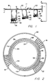
- Fig. 1 is a partial view in section illustrating three rows of stator vanes for a compressor of a gas turbine engine incorporating this invention;
- Fig. 2 is a front plan view of the stator vanes taken along line 2-2 in Fig. 1;
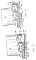
- Fig. 3 is an enlarged view in section of one row of stator vanes incorporating this invention;
- Fig. 4 is an enlarged view in section of another row of stator vanes incorporating this invention; and
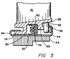
- Fig. 5 is an enlarged view in section of another row of stator vanes incorporating this invention where the E-shaped spring damper is disposed in a different orientation from the damper depicted in Figs. 3 and 4.
-
- While this invention in its preferred embodiment has particular utility for gas turbine engines, as one skilled in this art will appreciate, it has application in rotating machinery in other environments. Suffice it to say that this invention is particularly efficacious for damping vibratory stresses for rotating machinery where there is very little room available to accommodate dampers.
- As best seen in Fig. 1 which is a partial view illustrating the stator section of a high pressure compressor for a gas turbine engine, the stator section generally illustrated by
reference numeral 10 comprises three (3) rows ofvanes outer shrouds inner shroud vanes inner shrouds annular honeycomb segments inner shrouds outer shrouds drum rotor 36 that carries the compressor rotor blades (not shown) that are rotary mounted to extend adjacent to the respective vanes and to receive the engine working medium to be compressed is shown to illustrate theteeth 38 of the labyrinth seal and how it cooperates with the respective honeycomb segments. As this invention is only concerned with the damper aspects of the compressor stator, for the sake of convenience and simplicity the details of the compressor and gas turbine engine are omitted herefrom. For further details reference should be made to U. S. Patent Number 5,127,794. - As noted in Figs. 1 and 3-5, the segmented
back rings flanges back rings Pins inner shrouds members - What has been described in the immediate paragraphs above is the typical and well known design for compressor stators in gas turbine engines. These component parts may be fabricated or cast. As mentioned earlier, when the parts are cast, the cast parts cannot damp out the vibrations encountered. As a consequence, this vibratory energy can lead to the malfunction or destruction of the component parts of the stator.
- As noted in these designs, a cavity is formed between the end flange and the depending member. This invention has been able to capitalize on this envelope and utilize this cavity, notwithstanding the fact that in actuality this area provides very little space. A judiciously shaped damper is discretely located so as to provide sufficient frictional damping to attenuate the frequencies encountered in this environment.
- In accordance with this invention,
dampers cavities inner shrouds - As is apparent from the foregoing, the E-shaped damper is relatively simple to make and is effective to work in confined spaces and hence requires a minimum of space. As noted above, since it is flexible in its design, as one skilled in this art will appreciate, it has potential for being utilized for other applications. Because of its shape, the spring damper has a large load variation available which makes it efficacious in the hostile environment encountered in gas turbine engines. Of noteworthiness is the fact that because the E-shaped damper has a large deflection capability, it overcomes the problem of tolerance accumulation usually encountered with cast compressor stators.
- FIG. 5 exemplifies how the E-shaped damper may be assembled in similar applications for compressor stators. In this configuration the "E" of the E-shaped damper is rotated 90 degrees so that the end legs of the E-shaped damper bear against the
bottom surface 90 of the inner diameter of theinner shroud 28 and theouter surface 92 of the honeycomb segmentedback ring 44. Identical results are obtainable in either configuration and the orientation of the E-shaped damper will depend on the particular design configuration.
Claims (5)
- In combination, a stator (10) for rotating machinery comprising:characterised in that said combination further comprises:integrally cast stator vanes (12;14;16) ;an inner and outer shroud (18,24;20,26;22,28), the inner shroud (24;26;28) being disposed adjacent to the inner diameter of said stator vanes (12;14;16) and defining an annular surface;a segmented honeycomb seal element (30;32;34) concentrically supported to the inner shroud (24;26;28) and defining with said annular surface an annular cavity (76;78;80) ; andsegmented back rings (40;42;44) supporting said segmented honeycomb seal element (30;32;34) and support means (46-56) to support said segmented back rings (40;42;44) to said stator;an E-shaped mechanical damper (70;72;74) being E-shaped in cross-section and fabricated from flexible, resilient spring material adaptable to form an annular shape to fit within said annular cavity (76;78;80) and bear against the surface of said inner shroud (24;26;28) in frictional relationship to dissipate energy of the vibratory motion imparted to said stator (10);wherein the inner shroud (24;26;28) further comprises a pair of spaced radial depending walls (64;66;68) defining said annular cavity (76;78;80) of said inner shroud (24;26;28), said E-shaped mechanical damper (70;72;74) including a pair of end legs, one of said end legs bearing against one of said pair of radial depending walls; andwherein said segmented back rings (40;42;44) include a radial extending portion bearing against one of said radial depending walls (64;66;68), and the other of said end legs of said E-shaped damper (70;72;74) bears against said radial extending portion of said segmented back rings (40;42;44).
- In combination, a stator (10) for rotating machinery comprising:characterised in that said combination further comprises:integrally cast stator vanes (12;14;16) ;an inner and outer shroud (18,24;20,26;22,28), the inner shroud (24;26;28) being disposed adjacent to the inner diameter of said stator vanes (12;14;16) and defining an annular surface;a segmented honeycomb seal element (30;32;34) concentrically supported to the inner shroud (24;26;28) and defining with said annular surface an annular cavity (76;78;80) ; andsegmented back rings (40;42;44) supporting said segmented honeycomb seal element (30;32;34) and support means (46-56) to support said segmented back rings (40;42;44) to said stator;an E-shaped mechanical damper (70;72;74) being E-shaped in cross-section and fabricated from flexible, resilient spring material adaptable to form an annular shape to fit within said annular cavity (76;78;80) and bear against the surface of said inner shroud (24;26;28) in frictional relationship to dissipate energy of the vibratory motion imparted-to said stator (10); andwherein the E-shaped damper (70;72;74) includes end legs, one of said end legs bearing against the inner surface (90) of said inner shroud (24;26;28) and the other of said end legs bearing against the outer surface (92) of said segmented back rings (40;42;44).
- The combination as claimed in claim 1 or 2, wherein the inner shroud (24;26;28) is disposed in the compressor of a gas turbine engine and said compressor includes a drum rotor (36) having radially extending teeth (38) that engage the honeycomb of said segmented honeycomb seal element (30;32;34) to form a seal to prevent leakage of the working fluid medium of said gas turbine engine.
- The combination as claimed in any preceding claim, wherein said support means (46-56) includes axially extending flanges (46-56) disposed on opposite axial sides of said inner shroud (24;26;28), and said segmented back rings (40;42;44) include complementary U-shaped side portions defining annular channels to accommodate each of said axially extending flanges (46-56).
- The combination of any preceding claim, wherein said E-shaped damper (70;72;74) is circumferentially segmented.
Applications Claiming Priority (2)
| Application Number | Priority Date | Filing Date | Title |
|---|---|---|---|
| US52874 | 1979-06-28 | ||
| US08/052,874 US5346362A (en) | 1993-04-26 | 1993-04-26 | Mechanical damper |
Publications (2)
| Publication Number | Publication Date |
|---|---|
| EP0639692A1 EP0639692A1 (en) | 1995-02-22 |
| EP0639692B1 true EP0639692B1 (en) | 1999-06-30 |
Family
ID=21980465
Family Applications (1)
| Application Number | Title | Priority Date | Filing Date |
|---|---|---|---|
| EP94302982A Expired - Lifetime EP0639692B1 (en) | 1993-04-26 | 1994-04-26 | Mechanical damper |
Country Status (4)
| Country | Link |
|---|---|
| US (1) | US5346362A (en) |
| EP (1) | EP0639692B1 (en) |
| JP (1) | JP3461562B2 (en) |
| DE (1) | DE69419287T2 (en) |
Families Citing this family (55)
| Publication number | Priority date | Publication date | Assignee | Title |
|---|---|---|---|---|
| US5411370A (en) * | 1994-08-01 | 1995-05-02 | United Technologies Corporation | Vibration damping shroud for a turbomachine vane |
| US5639211A (en) * | 1995-11-30 | 1997-06-17 | United Technology Corporation | Brush seal for stator of a gas turbine engine case |
| JP3357377B2 (en) * | 1997-09-03 | 2002-12-16 | キョードー‐アライド・インダストリーズ・プライベート・リミテッド | Method and apparatus for minimizing noise from fan router units |
| US6042334A (en) * | 1998-08-17 | 2000-03-28 | General Electric Company | Compressor interstage seal |
| US6206155B1 (en) | 1998-09-22 | 2001-03-27 | The Unites States Of America As Represented By The Administrator Of The National Aeronautics And Space Administration | Energy absorbing protective shroud |
| US6113349A (en) * | 1998-09-28 | 2000-09-05 | General Electric Company | Turbine assembly containing an inner shroud |
| US6183192B1 (en) * | 1999-03-22 | 2001-02-06 | General Electric Company | Durable turbine nozzle |
| US6827551B1 (en) | 2000-02-01 | 2004-12-07 | The United States Of America As Represented By The Administrator Of The National Aeronautics And Space Administration | Self-tuning impact damper for rotating blades |
| DE10016912C1 (en) * | 2000-04-05 | 2001-12-13 | Aerodyn Eng Gmbh | Operation of offshore wind turbines dependent on the natural frequency of the tower |
| US6630761B1 (en) | 2000-08-10 | 2003-10-07 | Christopher W. Gabrys | Combination mechanical and magnetic support for a flywheel power supply |
| US6464215B1 (en) | 2000-09-25 | 2002-10-15 | Aer Energy Resources, Inc. | Vibration damping mount for a metal-air battery or the like |
| US7679245B2 (en) * | 2001-09-17 | 2010-03-16 | Beacon Power Corporation | Repulsive lift systems, flywheel energy storage systems utilizing such systems and methods related thereto |
| US6901821B2 (en) * | 2001-11-20 | 2005-06-07 | United Technologies Corporation | Stator damper anti-rotation assembly |
| DE10223997A1 (en) * | 2002-05-29 | 2003-12-18 | Infineon Technologies Ag | Process for the production of photomasks for structuring semiconductor substrates by optical lithography |
| GB0224962D0 (en) * | 2002-10-26 | 2002-12-04 | Rolls Royce Plc | Seal apparatus |
| US7291946B2 (en) * | 2003-01-27 | 2007-11-06 | United Technologies Corporation | Damper for stator assembly |
| US7032904B2 (en) * | 2003-08-13 | 2006-04-25 | United Technologies Corporation | Inner air seal anti-rotation device |
| US6942203B2 (en) * | 2003-11-04 | 2005-09-13 | General Electric Company | Spring mass damper system for turbine shrouds |
| JP4918263B2 (en) * | 2006-01-27 | 2012-04-18 | 三菱重工業株式会社 | Stator blade ring of axial compressor |
| US20070273104A1 (en) * | 2006-05-26 | 2007-11-29 | Siemens Power Generation, Inc. | Abradable labyrinth tooth seal |
| US9067091B2 (en) * | 2006-08-25 | 2015-06-30 | Siemens Industry, Inc. | Damper actuator assembly with speed control |
| US8950069B2 (en) * | 2006-12-29 | 2015-02-10 | Rolls-Royce North American Technologies, Inc. | Integrated compressor vane casing |
| JP2009068338A (en) * | 2007-09-10 | 2009-04-02 | Ihi Corp | Vibration reduction structure of wing |
| US8851844B2 (en) * | 2007-10-31 | 2014-10-07 | Mitsubishi Heavy Industries, Ltd. | Stationary blade and steam turbine |
| US8197189B2 (en) * | 2007-11-27 | 2012-06-12 | Pratt & Whitney Canada Corp. | Vibration damping of a static part using a retaining ring |
| US8033786B2 (en) * | 2007-12-12 | 2011-10-11 | Pratt & Whitney Canada Corp. | Axial loading element for turbine vane |
| US8500394B2 (en) | 2008-02-20 | 2013-08-06 | United Technologies Corporation | Single channel inner diameter shroud with lightweight inner core |
| FR2928961B1 (en) * | 2008-03-19 | 2015-11-13 | Snecma | SECTORIZED DISPENSER FOR A TURBOMACHINE. |
| FR2930592B1 (en) * | 2008-04-24 | 2010-04-30 | Snecma | TURBINE DISPENSER FOR A TURBOMACHINE |
| EP3054169B1 (en) * | 2008-12-25 | 2019-02-20 | Mitsubishi Hitachi Power Systems, Ltd. | Stator blade assembly and gas turbine |
| JP5501611B2 (en) * | 2008-12-25 | 2014-05-28 | 三菱重工業株式会社 | Turbine blade and gas turbine |
| FR2971022B1 (en) | 2011-02-02 | 2013-01-04 | Snecma | COMPRESSOR RECTIFIER STAGE FOR A TURBOMACHINE |
| US9151170B2 (en) * | 2011-06-28 | 2015-10-06 | United Technologies Corporation | Damper for an integrally bladed rotor |
| US8926269B2 (en) * | 2011-09-06 | 2015-01-06 | General Electric Company | Stepped, conical honeycomb seal carrier |
| US9109458B2 (en) * | 2011-11-11 | 2015-08-18 | United Technologies Corporation | Turbomachinery seal |
| US9045985B2 (en) | 2012-05-31 | 2015-06-02 | United Technologies Corporation | Stator vane bumper ring |
| EP2728123A1 (en) | 2012-11-06 | 2014-05-07 | MTU Aero Engines GmbH | Fluid flow engine and corresponding assembly method of a fluid flow engine |
| US9279325B2 (en) | 2012-11-08 | 2016-03-08 | General Electric Company | Turbomachine wheel assembly having slotted flanges |
| JP6121152B2 (en) * | 2012-12-07 | 2017-04-26 | 三菱日立パワーシステムズ株式会社 | Turbine blade and turbine |
| US10619496B2 (en) * | 2013-06-14 | 2020-04-14 | United Technologies Corporation | Turbine vane with variable trailing edge inner radius |
| WO2015076906A2 (en) * | 2013-09-10 | 2015-05-28 | United Technologies Corporation | Plug seal for gas turbine engine |
| EP3047130B1 (en) * | 2013-09-18 | 2020-01-15 | United Technologies Corporation | A gas turbine seal assembly comprising splined honeycomb seals |
| US10119410B2 (en) | 2013-10-03 | 2018-11-06 | United Technologies Corporation | Vane seal system having spring positively locating seal member in axial direction |
| US20150292344A1 (en) * | 2014-04-11 | 2015-10-15 | United Technologies Corporation | Ingestion blocking endwall feature |
| US10329931B2 (en) * | 2014-10-01 | 2019-06-25 | United Technologies Corporation | Stator assembly for a gas turbine engine |
| US9790809B2 (en) * | 2015-03-24 | 2017-10-17 | United Technologies Corporation | Damper for stator assembly |
| US10677312B2 (en) * | 2018-02-15 | 2020-06-09 | General Electric Company | Friction shaft damper for axial vibration mode |
| US11136896B2 (en) * | 2019-04-24 | 2021-10-05 | Raytheon Technologies Corporation | Rotating leaf spring seal |
| IT201900013218A1 (en) * | 2019-07-29 | 2021-01-29 | Ge Avio Srl | INTERNAL BAND FOR TURBINE ENGINE. |
| FR3108675B1 (en) * | 2020-03-25 | 2022-11-04 | Safran Aircraft Engines | Turbomachine stator distributor comprising a continuous and free sealing ring |
| FR3111383B1 (en) * | 2020-06-11 | 2022-05-13 | Safran Aircraft Engines | AIRCRAFT TURBOMACHINE RECTIFIER STAGE SYSTEM |
| FR3113298B1 (en) * | 2020-08-10 | 2023-09-01 | Safran Aircraft Engines | Abradable holder for a low pressure distributor comprising a single sheet |
| WO2022168951A1 (en) * | 2021-02-05 | 2022-08-11 | 三菱パワー株式会社 | Stationary vane ring and rotary machine |
| FR3119861B1 (en) * | 2021-02-12 | 2023-08-25 | Safran Aircraft Engines | Device for maintaining a turbomachine blade in position |
| CN113898421A (en) * | 2021-10-10 | 2022-01-07 | 中国航发沈阳发动机研究所 | Compressor stator inner ring and rotor stator sealing connection structure thereof |
Family Cites Families (14)
| Publication number | Priority date | Publication date | Assignee | Title |
|---|---|---|---|---|
| US3326523A (en) * | 1965-12-06 | 1967-06-20 | Gen Electric | Stator vane assembly having composite sectors |
| US4030288A (en) * | 1975-11-10 | 1977-06-21 | Caterpillar Tractor Co. | Modular gas turbine engine assembly |
| US4121843A (en) | 1977-10-04 | 1978-10-24 | Pressure Science, Incorporated | Multiple convolution sealing ring |
| US4199151A (en) * | 1978-08-14 | 1980-04-22 | General Electric Company | Method and apparatus for retaining seals |
| US4314792A (en) * | 1978-12-20 | 1982-02-09 | United Technologies Corporation | Turbine seal and vane damper |
| US4285633A (en) | 1979-10-26 | 1981-08-25 | The United States Of America As Represented By The Secretary Of The Air Force | Broad spectrum vibration damper assembly fixed stator vanes of axial flow compressor |
| US4621976A (en) * | 1985-04-23 | 1986-11-11 | United Technologies Corporation | Integrally cast vane and shroud stator with damper |
| US4721434A (en) * | 1986-12-03 | 1988-01-26 | United Technologies Corporation | Damping means for a stator |
| US4897021A (en) * | 1988-06-02 | 1990-01-30 | United Technologies Corporation | Stator vane asssembly for an axial flow rotary machine |
| FR2646221B1 (en) | 1989-04-19 | 1991-06-14 | Snecma | SEAL, DEVICE COMPRISING SAME AND APPLICATION TO A TURBOMACHINE |
| GB2239678B (en) * | 1989-12-08 | 1993-03-03 | Rolls Royce Plc | Gas turbine engine blade shroud assembly |
| US5127794A (en) * | 1990-09-12 | 1992-07-07 | United Technologies Corporation | Compressor case with controlled thermal environment |
| US5149250A (en) * | 1991-02-28 | 1992-09-22 | General Electric Company | Gas turbine vane assembly seal and support system |
| US5188507A (en) * | 1991-11-27 | 1993-02-23 | General Electric Company | Low-pressure turbine shroud |
-
1993
- 1993-04-26 US US08/052,874 patent/US5346362A/en not_active Expired - Lifetime
-
1994
- 1994-04-26 EP EP94302982A patent/EP0639692B1/en not_active Expired - Lifetime
- 1994-04-26 DE DE69419287T patent/DE69419287T2/en not_active Expired - Fee Related
- 1994-04-26 JP JP08833194A patent/JP3461562B2/en not_active Expired - Fee Related
Also Published As
| Publication number | Publication date |
|---|---|
| DE69419287D1 (en) | 1999-08-05 |
| US5346362A (en) | 1994-09-13 |
| JP3461562B2 (en) | 2003-10-27 |
| JPH06346703A (en) | 1994-12-20 |
| DE69419287T2 (en) | 2000-01-20 |
| EP0639692A1 (en) | 1995-02-22 |
Similar Documents
| Publication | Publication Date | Title |
|---|---|---|
| EP0639692A1 (en) | Mechanical damper | |
| US4621976A (en) | Integrally cast vane and shroud stator with damper | |
| US3326523A (en) | Stator vane assembly having composite sectors | |
| US7435049B2 (en) | Sealing device and method for turbomachinery | |
| EP1741878B1 (en) | Fluid flow machine | |
| US8105016B2 (en) | Damping arrangement for guide vanes | |
| US4361213A (en) | Vibration damper ring | |
| US3126149A (en) | Foamed aluminum honeycomb motor | |
| US4305696A (en) | Stator vane assembly for a gas turbine engine | |
| US5482433A (en) | Integral inner and outer shrouds and vanes | |
| EP2472065B1 (en) | Damper coverplate and sealing arrangement for turbine bucket shank | |
| US4743166A (en) | Blade root seal | |
| US9328926B2 (en) | Segmented combustion chamber head | |
| JPH11247999A (en) | Seal device of rotary machine | |
| US4721434A (en) | Damping means for a stator | |
| GB2117843A (en) | Compressor shrouds | |
| WO1998053228A1 (en) | Interstage vane seal apparatus | |
| JPH0223204A (en) | Mounting structure of stator blade for axial-flow rotary machine and spring used for said mounting structure | |
| EP1510655B1 (en) | Brush seal support | |
| CA2483391A1 (en) | Attachment of a ceramic shroud in a metal housing | |
| US20090214347A1 (en) | Split ring for a rotary part of a turbomachine | |
| KR100558796B1 (en) | An anti-rotation device and a stator assembly | |
| US5215432A (en) | Stator vane damper | |
| EP1712743A2 (en) | Turbine with an abradable seal between the rotor and a stationary component | |
| US7572098B1 (en) | Vane ring with a damper |
Legal Events
| Date | Code | Title | Description |
|---|---|---|---|
| PUAI | Public reference made under article 153(3) epc to a published international application that has entered the european phase |
Free format text: ORIGINAL CODE: 0009012 |
|
| AK | Designated contracting states |
Kind code of ref document: A1 Designated state(s): DE FR GB |
|
| 17P | Request for examination filed |
Effective date: 19950306 |
|
| 17Q | First examination report despatched |
Effective date: 19960130 |
|
| GRAG | Despatch of communication of intention to grant |
Free format text: ORIGINAL CODE: EPIDOS AGRA |
|
| GRAG | Despatch of communication of intention to grant |
Free format text: ORIGINAL CODE: EPIDOS AGRA |
|
| GRAH | Despatch of communication of intention to grant a patent |
Free format text: ORIGINAL CODE: EPIDOS IGRA |
|
| GRAH | Despatch of communication of intention to grant a patent |
Free format text: ORIGINAL CODE: EPIDOS IGRA |
|
| GRAA | (expected) grant |
Free format text: ORIGINAL CODE: 0009210 |
|
| AK | Designated contracting states |
Kind code of ref document: B1 Designated state(s): DE FR GB |
|
| REF | Corresponds to: |
Ref document number: 69419287 Country of ref document: DE Date of ref document: 19990805 |
|
| ET | Fr: translation filed | ||
| PLBE | No opposition filed within time limit |
Free format text: ORIGINAL CODE: 0009261 |
|
| STAA | Information on the status of an ep patent application or granted ep patent |
Free format text: STATUS: NO OPPOSITION FILED WITHIN TIME LIMIT |
|
| 26N | No opposition filed | ||
| REG | Reference to a national code |
Ref country code: GB Ref legal event code: IF02 |
|
| PGFP | Annual fee paid to national office [announced via postgrant information from national office to epo] |
Ref country code: DE Payment date: 20080430 Year of fee payment: 15 |
|
| PGFP | Annual fee paid to national office [announced via postgrant information from national office to epo] |
Ref country code: FR Payment date: 20080403 Year of fee payment: 15 |
|
| REG | Reference to a national code |
Ref country code: FR Ref legal event code: ST Effective date: 20091231 |
|
| PG25 | Lapsed in a contracting state [announced via postgrant information from national office to epo] |
Ref country code: DE Free format text: LAPSE BECAUSE OF NON-PAYMENT OF DUE FEES Effective date: 20091103 |
|
| PG25 | Lapsed in a contracting state [announced via postgrant information from national office to epo] |
Ref country code: FR Free format text: LAPSE BECAUSE OF NON-PAYMENT OF DUE FEES Effective date: 20091222 |
|
| PGFP | Annual fee paid to national office [announced via postgrant information from national office to epo] |
Ref country code: GB Payment date: 20130424 Year of fee payment: 20 |
|
| REG | Reference to a national code |
Ref country code: GB Ref legal event code: PE20 Expiry date: 20140425 |
|
| PG25 | Lapsed in a contracting state [announced via postgrant information from national office to epo] |
Ref country code: GB Free format text: LAPSE BECAUSE OF EXPIRATION OF PROTECTION Effective date: 20140425 |