EP0639689A2 - Multiple stage well cementing apparatus - Google Patents
Multiple stage well cementing apparatus Download PDFInfo
- Publication number
- EP0639689A2 EP0639689A2 EP94304412A EP94304412A EP0639689A2 EP 0639689 A2 EP0639689 A2 EP 0639689A2 EP 94304412 A EP94304412 A EP 94304412A EP 94304412 A EP94304412 A EP 94304412A EP 0639689 A2 EP0639689 A2 EP 0639689A2
- Authority
- EP
- European Patent Office
- Prior art keywords
- sleeve
- assembly
- housing
- port
- tapered
- Prior art date
- Legal status (The legal status is an assumption and is not a legal conclusion. Google has not performed a legal analysis and makes no representation as to the accuracy of the status listed.)
- Withdrawn
Links
- 239000012530 fluid Substances 0.000 claims abstract description 18
- 230000000717 retained effect Effects 0.000 claims abstract description 16
- 238000007789 sealing Methods 0.000 claims description 19
- 230000007704 transition Effects 0.000 description 12
- 239000004568 cement Substances 0.000 description 10
- 125000006850 spacer group Chemical group 0.000 description 10
- 239000002002 slurry Substances 0.000 description 8
- 238000004891 communication Methods 0.000 description 4
- 230000002829 reductive effect Effects 0.000 description 3
- XAGFODPZIPBFFR-UHFFFAOYSA-N aluminium Chemical compound [Al] XAGFODPZIPBFFR-UHFFFAOYSA-N 0.000 description 2
- 229910052782 aluminium Inorganic materials 0.000 description 2
- 230000003247 decreasing effect Effects 0.000 description 2
- 238000005553 drilling Methods 0.000 description 2
- 239000000463 material Substances 0.000 description 2
- 238000000034 method Methods 0.000 description 2
- 230000008439 repair process Effects 0.000 description 2
- 229910001018 Cast iron Inorganic materials 0.000 description 1
- 229910000831 Steel Inorganic materials 0.000 description 1
- 230000000712 assembly Effects 0.000 description 1
- 238000000429 assembly Methods 0.000 description 1
- 230000015572 biosynthetic process Effects 0.000 description 1
- 230000007797 corrosion Effects 0.000 description 1
- 238000005260 corrosion Methods 0.000 description 1
- 230000008878 coupling Effects 0.000 description 1
- 238000010168 coupling process Methods 0.000 description 1
- 238000005859 coupling reaction Methods 0.000 description 1
- 230000007812 deficiency Effects 0.000 description 1
- 230000006866 deterioration Effects 0.000 description 1
- 239000013536 elastomeric material Substances 0.000 description 1
- 230000002401 inhibitory effect Effects 0.000 description 1
- 239000000203 mixture Substances 0.000 description 1
- 238000012986 modification Methods 0.000 description 1
- 230000004048 modification Effects 0.000 description 1
- 238000005086 pumping Methods 0.000 description 1
- 230000000246 remedial effect Effects 0.000 description 1
- 239000010959 steel Substances 0.000 description 1
Images


Classifications
-
- E—FIXED CONSTRUCTIONS
- E21—EARTH DRILLING; MINING
- E21B—EARTH DRILLING, e.g. DEEP DRILLING; OBTAINING OIL, GAS, WATER, SOLUBLE OR MELTABLE MATERIALS OR A SLURRY OF MINERALS FROM WELLS
- E21B34/00—Valve arrangements for boreholes or wells
- E21B34/06—Valve arrangements for boreholes or wells in wells
- E21B34/14—Valve arrangements for boreholes or wells in wells operated by movement of tools, e.g. sleeve valves operated by pistons or wire line tools
-
- E—FIXED CONSTRUCTIONS
- E21—EARTH DRILLING; MINING
- E21B—EARTH DRILLING, e.g. DEEP DRILLING; OBTAINING OIL, GAS, WATER, SOLUBLE OR MELTABLE MATERIALS OR A SLURRY OF MINERALS FROM WELLS
- E21B33/00—Sealing or packing boreholes or wells
- E21B33/10—Sealing or packing boreholes or wells in the borehole
- E21B33/13—Methods or devices for cementing, for plugging holes, crevices, or the like
- E21B33/14—Methods or devices for cementing, for plugging holes, crevices, or the like for cementing casings into boreholes
- E21B33/146—Stage cementing, i.e. discharging cement from casing at different levels
-
- E—FIXED CONSTRUCTIONS
- E21—EARTH DRILLING; MINING
- E21B—EARTH DRILLING, e.g. DEEP DRILLING; OBTAINING OIL, GAS, WATER, SOLUBLE OR MELTABLE MATERIALS OR A SLURRY OF MINERALS FROM WELLS
- E21B33/00—Sealing or packing boreholes or wells
- E21B33/10—Sealing or packing boreholes or wells in the borehole
- E21B33/13—Methods or devices for cementing, for plugging holes, crevices, or the like
- E21B33/14—Methods or devices for cementing, for plugging holes, crevices, or the like for cementing casings into boreholes
- E21B33/16—Methods or devices for cementing, for plugging holes, crevices, or the like for cementing casings into boreholes using plugs for isolating cement charge; Plugs therefor
- E21B33/167—Cementing plugs provided with anti-rotation mechanisms, e.g. for easier drill-out
Definitions
- the present invention relates generally to apparatus for cementing a well and, more specifically, to apparatus for multiple stage cementing particularly useful in cementing operations performed within an existing casing string, otherwise known as "secondary cementing" operations.
- Secondary cementing procedures are utilized in wells during their productive lives, such as remedial cementing and repairs to existing cemented areas. This may be necessitated by a number of occurrences. For example, the inside surface of an existing casing string will often corrode or otherwise deteriorate over time, thereby decreasing fluid flow through the string. In addition, the corrosion may cause the casing string to become fluid permeable, thereby leading to fluid leakage. At such time, secondary cementing may be utilized to repair the deteriorated section of casing. In such operations, when the well cannot be cemented from the bottom of the casing, it is often preferable to cement the annulus in two or more stages. For example, two stage cementing may be necessitated when the formation will not support a column of cement slurry over the vertical zone to be cemented.
- an apparatus for cementing multiple stages within a well which apparatus comprises a housing assembly, said housing assembly having at least one port therein; a first sleeve retained within said housing, said sleeve being movable from a first position covering said port to a second position opening said port; a second sleeve assembly, said sleeve assembly being movable from a first position away from said port to a second position covering said port; said housing assembly further comprising an inwardly extending tapered shoulder, and said first sleeve comprising a tapered surface, said tapered shoulder and said tapered surface being cooperatively engageable such that engagement of said tapered surface with said tapered shoulder establishes said second position of said first sleeve and such that said engagement of said tapered surface with said tapered shoulder inhibits relation of said first sleeve relative to said housing assembly.
- the invention also provides a system for cementing multiple stages within a well, which system comprises a cementing valve assembly which valve assembly comprises a housing assembly defining at least one radial port; a first sleeve assembly, slightly retained within said housing for longitudinal movement relative thereto, said sleeve being movable from a first position substantially covering said port to a second position substantially opening said port; a second sleeve assembly retained within said housing for longitudinal movement relative thereto, said second sleeve assembly comprising a sealing sleeve and an actuation sleeve, said sealing sleeve being releasably coupled to said actuation sleeve, said second sleeve assembly being movable from a first position wherein said sealing sleeve is longitudinally above said port, to a second position wherein said sealing sleeve is substantially adjacent to and covering said port; said housing defining a generally radially extending engagement surface, and said first sleeve including a tapered
- the present invention provides a new method and apparatus for cementing multiple stages within a well.
- the apparatus includes a housing assembly which will define at least one cementing port, and which will preferably define a plurality of cementing ports.
- a first sleeve assembly is retained within the housing and is movable from a first position wherein the sleeve covers the cementing port, and thereby precludes fluid flow therethrough, to a second position wherein the sleeve opens the cementing port.
- the apparatus also includes a second sleeve assembly which is movable from a first position away from the cementing port, to a second position wherein the second sleeve assembly covers the port and precludes fluid flow therethrough.
- the housing assembly preferably defines an inwardly extending tapered shoulder surface which cooperates with a tapered surface on the first sleeve assembly such that the shoulder surface and the first sleeve surface are cooperatively engageable.
- the first and second sleeve assemblies are longitudinally movable relative to said housing, and therefore relative to said port, and said inwardly extending shoulder of said housing defines the second position of the first sleeve.
- the apparatus will include an engagement system, such as a lug and slot between the first sleeve and the closing seat, to minimise relative rotation between the two members when the two members are proximate one another.
- an engagement system such as a lug and slot between the first sleeve and the closing seat
- the closing seat may be released from the closing sleeve and moved to a third position.
- the first sleeve is in the described second position, and the closing seat is in a third position. In these positions, the first sleeve assembly will engage the inwardly extending shoulder of the housing to prevent relative rotation between the first sleeve assembly and the housing assembly, thereby facilitating the "drilling out" of the members to establish an open bore.
- multi-stage cementing tool 10 will be coupled in a string of casing or tubing to form a cementing assembly in a manner well-known to those skilled in the art. The assembly will then be lowered into the wellbore to a depth at which it is desired to cement the assembly in place.
- Multi-stage cementing tool 10 includes a housing assembly 12 having an upper housing section 14 and a lower housing section 16.
- Upper housing section 14 defines a first, upper, bore 20 and a longitudinally offset, but generally coaxial, second, lower, bore 18.
- Upper bore 20 is of a first, relatively small, diameter, while lower bore 18 is of a relatively enlarged diameter. The transition between upper and lower bores 20 and 18 is abrupt, forming a shoulder 21.
- Upper housing section 14 includes a plurality of generally radial ports 22 providing fluid communication between the interior and exterior of housing assembly 12 proximate lower bore 18 of upper housing section 14.
- two generally diametrically opposed ports 22 are provided in upper housing section 14.
- the inner surface of upper housing section 14 includes an annular recess 26 which extends partially across the horizon at which ports 22 are located, establishing a band having a diameter greater than that of lower bore 18.
- annular recess 26 which extends partially across the horizon at which ports 22 are located, establishing a band having a diameter greater than that of lower bore 18.
- the transition between annular recess 26 and lower bore 18 of upper housing section 14 is abrupt, forming a shoulder 28.
- the transition between annular recess 26 and lower bore 18 is relatively gradual, forming a tapered shoulder 30.
- Upper housing section 14 is preferably coupled to lower housing section 16 through a threaded coupling 17.
- Lower housing section 16 defines a first, upper, generally longitudinal bore 31 having an internal diameter essentially equal to that of upper bore 20 of upper housing section 14.
- Lower housing section 16 further includes a longitudinally offset second, intermediate, bore 35 having a relatively enlarged internal diameter. The transition between upper and intermediate bore sections 31 and 35 is relatively abrupt, forming a shoulder 33.
- Below second (intermediate) bore section 35 is a third bore 37 having an internal diameter which is relatively reduced relative to the diameters of bore sections 31 and 35.
- a tapered transition zone 36 is located between second (intermediate) bore section 35 and third bore section 37.
- Tapered transition zone 36 provides a smooth transition from the relatively large inside diameter in second bore section 35 to the relatively smaller inside diameter in third bore section 37 of lower housing 16.
- Upper, intermediate and lower bores 31, 35 and 37, respectively, of lower housing 16 are generally coaxial with one another, and are coaxial with upper and lower bores 18 and 20 of upper housing 14 when upper housing 14 and lower housing 16 are threadably coupled at 17 to form housing assembly 12.
- Multi-stage cementing tool 10 includes an annular opening sleeve 38 and a closing sleeve assembly 39.
- Closing sleeve assembly 39 includes a closing sleeve 40 and a closing seat 42.
- opening sleeve 38 isolates ports 22 in upper housing 14.
- First opening sleeve 38 is releasably secured in the unactuated position relative to housing assembly 12 by a plurality of shear pins 44. In one preferred embodiment, two shear pins 44 are used.
- Closing sleeve 40 is preferably an annular member which will selectively seal ports 22 in upper housing 14.
- Closing sleeve 40 is initially coupled to closing seat 42 by a plurality of releasable members, such as shear pins 48.
- Closing seat 42 will be initially retained with an upper end bore 20 and partially adjacent shoulder 21 by a plurality of shear pins 46.
- Shear pins 46 engage both closing seat 42 and upper housing section 14, and will initially retain closing seat 42, and thereby closing sleeve 40, in first, unactuated, position.
- closing seat 42 is retained in position by two shear pins 46 and closing sleeve 40 is retained in position by two shear pins 48.
- the yield strength of shear pins 46 is less than the yield strength of shear pins 48.
- Closing sleeve assembly 39 will therefore be releasable as a unit from upper housing 14 prior to the releasing of closing seat 42 from closing sleeve 40.
- Closing seat 42 and opening sleeve 38 are formed of any relatively rigid material which will be relatively drillable during drillout of closing seat 42 and opening sleeve 38.
- closing sleeve 42 and opening sleeve 38 are formed of aluminum.
- closing sleeve 42 and opening sleeve 38 can also be formed of cast iron.
- Closing sleeve 40 can be formed of any rigid material which will resist deterioration. Closing sleeve 40 is preferably formed of steel.
- a sealing member such as an O-ring 50 provides a fluid-tight seal between opening sleeve 38 and closing sleeve 40 when multi-stage cementing tool 10 is in the unactuated, or closed, position, as shown in FIG. 1.
- another sealing member such as O-ring 52, provides a fluid-tight seal between the outside surface of opening sleeve 38 and upper bore 31 of lower housing 16.
- a set of seals 54 and 55 retained within grooves 56 and 57, respectively, provide a fluid-tight seal between the outer surface of closing sleeve 40 and the inner surface defining lower bore 18 of upper housing 14.
- An O-ring 63 retained in a groove 53 in closing seat 42 provides a fluid-tight seal between closing sleeve 40 and closing seat 42.
- a locking ring 58 is retained in an annular groove 59 around the outer surface of closing sleeve 40.
- Locking ring 58 is an expanding-type split ring, as will be further discussed below.
- the circumferential surface of opening sleeve 38 includes one or more upwardly extending lugs 66 extending from proximate its upper end surface.
- the inner surface proximate the upper end of central bore 61 of opening sleeve 38 includes an annular taper to form a tapered seat 60.
- the lower end of opening sleeve 38 includes an externally tapered end to establish a circumferential chamfer 62.
- chamfer 62 of opening sleeve 38 has the same inclination as the inclination of tapered transition zone 36 in lower housing 16. However, the inclinations of the two tapered sections may be different.
- Chamfer 62 preferably includes a plurality of narrow longitudinal channels or grooves 63 from the lower end of opening sleeve 38 to the outer surface of opening sleeve 38 proximate shear pins 44.
- the lower circumferential lip 70 of closing seat 62 includes a circumferential recess 72.
- Lug 66 of opening sleeve 38 extends a smaller circumferential distance around upper lip 64 of opening sleeve 38, than the dimension of slot 72 around lower lip 70 of closing seat 42.
- lug 66 extends into slot 72.
- Closing seat 42 includes a taper at its upper inner surface to form a tapered seat 68.
- Lower housing section 16 includes a first, relatively large, outside diameter in upper region 32. Longitudinally adjacent and below upper region 32 is first packer seal receiving groove 75. The transition between upper region 32 and first packer receiving groove 75 is relatively abrupt, forming shoulder 73. In one preferred embodiment, shoulder 73 is located on the outer surface of lower housing 16 proximate and below the location on the outer surface which corresponds to tapered transition zone 36 on the inner surface of lower housing 16.
- First annular packer receiving groove 75 includes first and second component annular grooves 74a and 74b.
- First component annular groove 74a is relatively wide while second component annular groove 74b is lower, and relatively deeper.
- a second packer receiving groove 76 includes a relatively wide portion 77a and lower, relatively deeper, portion 77b.
- Adjacent and below first annular groove 74, and above annular groove 77 is a first annular ridge 78.
- Adjacent and below second annular groove 76 is a second annular ridge 80.
- the outside diameters of first and second annular ridges 78, 80 are preferably equal.
- the remainder of lower region 34 of lower housing 16 below second annular ridge 80 is of a relatively reduced diameter compared to that of upper region 32.
- a first packer cup 82 extends around lower mandrel 16, and is retained in first packer retaining groove 75.
- First packer cup 82 is preferably of a tapered radius, such that the diameter at the upper end of first packer cup 82 is greater than the diameter at the lower end of first packer cup 82.
- First packer cup 82 smoothly tapers from the diameter at the lower end of first packer cup 82 to the diameter at the upper end of first packer cup 82.
- a second packer cup 84 is retained in second packer retaining groove 76. The diameter of the upper end of second packer cup 84 is similarly greater than the diameter at the lower end of second packer cup 84.
- Second packer cup 84 smoothly tapers from the diameter at the lower end of second packer cup 84 to the diameter at the upper end of second packer cup 84.
- Packer cups 82 and 84 are each provided at their lower ends with an inwardly-extending protrusion or lip 86, 88, respectively, which extends into and is seated in a respective deeper annular grooves 74b, 77b, respectively.
- multi-stage cementing tool 10 The operation of multi-stage cementing tool 10 is as follows. After multi-stage cementing tool 10 has been assembled, as shown in FIG. 1, the tool is inserted as a portion of a workover casing string into the borehole. The upper end of first packer cup 82 and second packer cup 84 are in contact with the inner surface of the existing casing sidewalls as the workover casing string and associated multi-stage cementing tool 10 are lowered into the borehole.
- a spacer fluid is generally pumped down the workover casing string to clear mud and other debris out of the string.
- spacer plug may be a conventional apparatus known to the industry, typically including a mandrel with rubber wipers. The rubber wipers of the spacer plug clean the interior of the casing as the plug travels therethrough.
- the spacer plug also can be used to separate the spacer fluid from the first stage of cement slurry.
- the spacer plug is not required in applications where it is unimportant whether the spacer fluid and the cement slurry mix in the borehole annulus.
- the first stage of cement slurry is pumped through the casing string, out of the bottom of the casing string and up into the surrounding annulus.
- sealing plug 90 is dropped through the casing string, or is displaced behind the first stage of slurry, to engage opening seat 38.
- Free-fall plug 90 can be any of several plugs known to those skilled in the art.
- sealing plug 90 illustrated herein is a displacement-type plug.
- Sealing plug 90 includes coated body member 91, which is approximately 14 inches long. Body member 91 is provided at a lower end 92 with a first, lower, centralizer 94, and at its upper end 93 with second, upper, centralizer 95. Sealing plug 90 further includes upper and lower wipers 96, 98 between centralizers 94, 95.
- Centralizers 94 and 95 each have a decreased outside diameter compared to the outside diameter of wipers 96, 98 when wipers 96, 98 are fully extended.
- Centralizers 94 and 95, and wipers 96 and 98 are each preferably formed of an elastomeric material, such as rubber.
- Sealing plug 90 also includes a generally rigid seating block 100.
- the nominal diameter of centralizer 94 is greater than the inside diameter of, or bore through, opening sleeve 38.
- centralizer 94 will flex upward as sealing plug 90 continues downward, as will wipers 96, 98.
- Seating block 100 then seats in tapered seat 60 of opening sleeve 38. Sealing plug 90 is shown depicted with seating block 100 seated in tapered seat 60 of opening sleeve 38 in FIGS. 2 and 3.
- Seating block 100 has an outside diameter less than the inner diameter of closing seat 42, to enable seating block 100 to pass through closing seat 42 and seat in tapered seat 60.
- the multi-stage cementing tool 10 is still in the configuration shown in FIG. 1. As pressure is applied in the casing string above multi-stage cementing tool 10, shear pins 44 of opening sleeve 38 shear and opening sleeve 38 moves down from first bore section 31 and into second bore section 35 of upper region 32 of lower housing 16.
- opening sleeve 38 moves downwardly, O-ring 52 passes shoulder 33 and enters second bore section 35. O-ring 52 does not provide a fluid-tight seal in second bore section 35 because of the relatively enlarged diameter of second bore section 35 compared to that of first bore section 31. Opening sleeve 38 moves down until tapered region 62 of the outer surface of opening sleeve 38 engages and seats in tapered transition zone 36 of lower housing 16, as is shown in FIG. 2. Narrow grooves 63 provide fluid communication between upper housing 14 and lower region 34 of lower housing 16. With continuing reference to FIG. 2, ports 22 are exposed, thereby allowing fluid communication between the interior of the slimhole multi-stage cementing tool 10 and the borehole annulus.
- the second stage of cement slurry is pumped down the tubing string and through ports 22 in upper mandrel 14 into annulus 24 of well bore 11.
- a conventional, appropriately-sized closing plug is pumped into the casing string.
- the closing plug engages and seats in tapered seat 68 of closing seat 42.
- Closing seat 42 is held in a fixed position relative to upper mandrel 14 by shear pins 46. Pressure is applied within the workover casing until the pressure exceeds the design limits of shear pins 46. Shear pins 46 then shear and closing seat 42 moves downwardly.
- closing sleeve 40 Since closing sleeve 40 is shear-pinned to closing seat 42 by shear pins 48, closing sleeve 40 moves downward with closing seat 42.
- Locking ring 56 associated with closing sleeve 40 expands into annular recess 26 of upper housing 14 after locking ring 58 passes shoulder 28 of annular recess 26.
- narrow channels or grooves 63 in tapered region 62 of outer surface of opening sleeve 38 provide fluid communication between upper mandrel 14 and lower region 34 of lower mandrel 16. Thus, fluid is prevented from being trapped between opening sleeve 38 and closing seat 42 as closing seat 42 moves down, thereby allowing closing sleeve 40 to fully close and seal ports 22.
- O-rings 54, 55 provide a fluid-tight seal between closing sleeve 40 and second bore section 17 of upper housing 14 below and above ports 22, respectively. Should a force act on closing sleeve 40 in an upward direction, locking ring 58 will engage shoulder 28 of annular recess 26, thereby inhibiting further movement upward of closing sleeve 40. Pressure indicators at the surface will indicate when closing sleeve 40 has closed ports 22 in upper mandrel 14.
- closing sleeve 40 is restrained from further movement downward.
- shear pins 48 are sheared and closing seat 42 moves downwardly until lower lip 70 of closing seat 42 contacts upper lip 64 of opening sleeve 38.
- Extended lug 66 of opening sleeve 38 is received in slot 72 of closing seat 42 when upper lip 64 is in contact with lower lip 70 of closing seat 42.
- Opening sleeve 38 and closing seat 42 may be drilled out in a manner known to the art. Opening sleeve 38 is substantially prevented from rotation due to the force of friction between tapered transition zone 36 in lower mandrel 16 and tapered region 62 of opening sleeve 38. Likewise, closing seat 42 is prevented from rotating by the extended lug 66 and slot 72 combination.
- inserts may be inserted inside and seated in closing seat 42 and opening sleeve 38.
- Such a modified multi-stage cementing tool may then be used in conjunction with multi-stage cementing tool 10 to facilitate pumping a third stage of cement into the annulus between the casing string and the existing casing string or well-bore.
- the modified tool is inserted in the casing string below slimhole multi-stage cementing tool 10.
- a set of plugs having a relatively reduced outside diameter are used to actuate the modified slimhole multi-stage cementing tool.
- slimhole multi-stage cementing tool 10 without modifications is actuated as discussed above.
Abstract
A cementing tool for cementing multiple stages within a well includes a housing assembly (12) which defines one or more cementing ports (22). A first sleeve assembly (38) is retained within the housing (12) and is movable from a first position (Fig. 1), where the sleeve (38) covers the port (22), and thereby precludes fluid flow therethrough, to a second position (Fig. 3) wherein the sleeve opens the cementing port (22). A second sleeve assembly (39) is movable from a first position (Fig. 1) away from the cementing port (22) to a second position (Fig. 4) wherein the sleeve assembly covers the port (22). The first sleeve (38) is cooperatively configured with the housing assembly (12) to provide engaging surfaces which resist rotation of the first sleeve relative to the housing. Additionally, the first sleeve (38) and the second sleeve assembly (39) are configured to limit relative rotation when the two pieces are longitudinally adjacent one another.
Description
- The present invention relates generally to apparatus for cementing a well and, more specifically, to apparatus for multiple stage cementing particularly useful in cementing operations performed within an existing casing string, otherwise known as "secondary cementing" operations.
- Secondary cementing procedures are utilized in wells during their productive lives, such as remedial cementing and repairs to existing cemented areas. This may be necessitated by a number of occurrences. For example, the inside surface of an existing casing string will often corrode or otherwise deteriorate over time, thereby decreasing fluid flow through the string. In addition, the corrosion may cause the casing string to become fluid permeable, thereby leading to fluid leakage. At such time, secondary cementing may be utilized to repair the deteriorated section of casing. In such operations, when the well cannot be cemented from the bottom of the casing, it is often preferable to cement the annulus in two or more stages. For example, two stage cementing may be necessitated when the formation will not support a column of cement slurry over the vertical zone to be cemented.
- Conventional multi-stage cementing tools have suffered from the deficiencies of either being too large in diameter to be satisfactorily utilized in workover operations, or of having components which are relatively difficult to drill out to provide an optimally open bore through the casing once the operation is completed.
- We have now devised a multi-stage cementing tool which can be figured to provide an optimally minimized outer diameter, and which can have internal components adapted to facilitate drilling out of the components facilitating the establishing of a full open bore after the cementing operation is completed.
- According to the present invention, there is provided an apparatus for cementing multiple stages within a well, which apparatus comprises a housing assembly, said housing assembly having at least one port therein; a first sleeve retained within said housing, said sleeve being movable from a first position covering said port to a second position opening said port; a second sleeve assembly, said sleeve assembly being movable from a first position away from said port to a second position covering said port; said housing assembly further comprising an inwardly extending tapered shoulder, and said first sleeve comprising a tapered surface, said tapered shoulder and said tapered surface being cooperatively engageable such that engagement of said tapered surface with said tapered shoulder establishes said second position of said first sleeve and such that said engagement of said tapered surface with said tapered shoulder inhibits relation of said first sleeve relative to said housing assembly.
- The invention also provides a system for cementing multiple stages within a well, which system comprises a cementing valve assembly which valve assembly comprises a housing assembly defining at least one radial port; a first sleeve assembly, slightly retained within said housing for longitudinal movement relative thereto, said sleeve being movable from a first position substantially covering said port to a second position substantially opening said port; a second sleeve assembly retained within said housing for longitudinal movement relative thereto, said second sleeve assembly comprising a sealing sleeve and an actuation sleeve, said sealing sleeve being releasably coupled to said actuation sleeve, said second sleeve assembly being movable from a first position wherein said sealing sleeve is longitudinally above said port, to a second position wherein said sealing sleeve is substantially adjacent to and covering said port; said housing defining a generally radially extending engagement surface, and said first sleeve including a tapered wedging surface, said surfaces being cooperatively configured to establish a wedging engagement between said first sleeve and said housing assembly when said first sleeve is moved to said second position; and a first plug member which is selectively engageable with said first sleeve and adapted to block the flow fluid relative to said first sleeve such that the application of pressure above said first sleeve will cause movement of said first sleeve from said first position to said second position.
- The present invention provides a new method and apparatus for cementing multiple stages within a well. The apparatus includes a housing assembly which will define at least one cementing port, and which will preferably define a plurality of cementing ports. A first sleeve assembly is retained within the housing and is movable from a first position wherein the sleeve covers the cementing port, and thereby precludes fluid flow therethrough, to a second position wherein the sleeve opens the cementing port.
- The apparatus also includes a second sleeve assembly which is movable from a first position away from the cementing port, to a second position wherein the second sleeve assembly covers the port and precludes fluid flow therethrough. The housing assembly preferably defines an inwardly extending tapered shoulder surface which cooperates with a tapered surface on the first sleeve assembly such that the shoulder surface and the first sleeve surface are cooperatively engageable. In a particularly preferred embodiment, the first and second sleeve assemblies are longitudinally movable relative to said housing, and therefore relative to said port, and said inwardly extending shoulder of said housing defines the second position of the first sleeve.
- In this particularly preferred embodiment, the apparatus will include an engagement system, such as a lug and slot between the first sleeve and the closing seat, to minimise relative rotation between the two members when the two members are proximate one another. Accordingly, after the second sleeve assembly is moved to its second position, the closing seat may be released from the closing sleeve and moved to a third position. In this stage of operation, the first sleeve is in the described second position, and the closing seat is in a third position. In these positions, the first sleeve assembly will engage the inwardly extending shoulder of the housing to prevent relative rotation between the first sleeve assembly and the housing assembly, thereby facilitating the "drilling out" of the members to establish an open bore.
- In order that the invention may be more fully understood, reference is made to the accompanying drawings, in which:
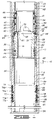
- FIG. 1 depicts one embodiment of multi-stage cementing tool in accordance with the present invention, depicted in a first, unactuated and closed, position; and illustrated partially in vertical section.
- FIG. 2 depicts the multi-stage cementing tool of Fig. 1 in a second actuated, position, illustrated partially in vertical section.
- FIG. 3 depicts the multi-stage cementing tool of Fig. 1 in a third, closed position, illustrated partially in vertical section, and
- FIG. 4 depicts the multi-stage tool of Fig. 1 in a fourth closed position illustrated partially in vertical section.
- Referring now to Fig. 1, therein is depicted an exemplary embodiment of a multi-stage cementing tool in accordance with the present invention, indicated generally at 10. In an intended operation,
multi-stage cementing tool 10 will be coupled in a string of casing or tubing to form a cementing assembly in a manner well-known to those skilled in the art. The assembly will then be lowered into the wellbore to a depth at which it is desired to cement the assembly in place. -
Multi-stage cementing tool 10 includes ahousing assembly 12 having anupper housing section 14 and alower housing section 16.Upper housing section 14 defines a first, upper, bore 20 and a longitudinally offset, but generally coaxial, second, lower, bore 18.Upper bore 20 is of a first, relatively small, diameter, whilelower bore 18 is of a relatively enlarged diameter. The transition between upper andlower bores shoulder 21. -
Upper housing section 14 includes a plurality of generallyradial ports 22 providing fluid communication between the interior and exterior ofhousing assembly 12 proximatelower bore 18 ofupper housing section 14. In one preferred embodiment, two generally diametrically opposedports 22 are provided inupper housing section 14. The inner surface ofupper housing section 14 includes anannular recess 26 which extends partially across the horizon at whichports 22 are located, establishing a band having a diameter greater than that oflower bore 18. At the upper end ofannular recess 26, the transition betweenannular recess 26 andlower bore 18 ofupper housing section 14 is abrupt, forming ashoulder 28. At the lower end ofannular recess 26, the transition betweenannular recess 26 andlower bore 18 is relatively gradual, forming atapered shoulder 30. -
Upper housing section 14 is preferably coupled tolower housing section 16 through a threadedcoupling 17.Lower housing section 16 defines a first, upper, generallylongitudinal bore 31 having an internal diameter essentially equal to that ofupper bore 20 ofupper housing section 14.Lower housing section 16 further includes a longitudinally offset second, intermediate, bore 35 having a relatively enlarged internal diameter. The transition between upper andintermediate bore sections shoulder 33. Below second (intermediate)bore section 35 is athird bore 37 having an internal diameter which is relatively reduced relative to the diameters ofbore sections tapered transition zone 36 is located between second (intermediate)bore section 35 andthird bore section 37. Taperedtransition zone 36 provides a smooth transition from the relatively large inside diameter insecond bore section 35 to the relatively smaller inside diameter inthird bore section 37 oflower housing 16. Upper, intermediate andlower bores lower housing 16 are generally coaxial with one another, and are coaxial with upper andlower bores upper housing 14 whenupper housing 14 andlower housing 16 are threadably coupled at 17 to formhousing assembly 12. -
Multi-stage cementing tool 10 includes anannular opening sleeve 38 and aclosing sleeve assembly 39. Closingsleeve assembly 39 includes aclosing sleeve 40 and aclosing seat 42. In a first, unactuated, position, openingsleeve 38isolates ports 22 inupper housing 14. First openingsleeve 38 is releasably secured in the unactuated position relative tohousing assembly 12 by a plurality ofshear pins 44. In one preferred embodiment, twoshear pins 44 are used. - Closing
sleeve 40 is preferably an annular member which will selectively sealports 22 inupper housing 14. Closingsleeve 40 is initially coupled to closingseat 42 by a plurality of releasable members, such asshear pins 48.Closing seat 42 will be initially retained with anupper end bore 20 and partiallyadjacent shoulder 21 by a plurality ofshear pins 46.Shear pins 46 engage bothclosing seat 42 andupper housing section 14, and will initially retainclosing seat 42, and thereby closingsleeve 40, in first, unactuated, position. In one preferred embodiment,closing seat 42 is retained in position by twoshear pins 46 and closingsleeve 40 is retained in position by twoshear pins 48. Preferably, the yield strength ofshear pins 46 is less than the yield strength ofshear pins 48. Closingsleeve assembly 39 will therefore be releasable as a unit fromupper housing 14 prior to the releasing ofclosing seat 42 from closingsleeve 40. -
Closing seat 42 andopening sleeve 38 are formed of any relatively rigid material which will be relatively drillable during drillout ofclosing seat 42 and openingsleeve 38. In a preferred embodiment, closingsleeve 42 and openingsleeve 38 are formed of aluminum. However, if aluminum does not provide sufficient integrity for a given application, closingsleeve 42 andopening sleeve 38 can also be formed of cast iron. Closingsleeve 40 can be formed of any rigid material which will resist deterioration. Closingsleeve 40 is preferably formed of steel. - A sealing member, such as an O-
ring 50 provides a fluid-tight seal betweenopening sleeve 38 and closingsleeve 40 whenmulti-stage cementing tool 10 is in the unactuated, or closed, position, as shown in FIG. 1. In a like manner, another sealing member, such as O-ring 52, provides a fluid-tight seal between the outside surface of openingsleeve 38 andupper bore 31 oflower housing 16. A set ofseals grooves sleeve 40 and the inner surface defininglower bore 18 ofupper housing 14. An O-ring 63 retained in agroove 53 in closingseat 42 provides a fluid-tight seal between closingsleeve 40 and closingseat 42. A lockingring 58 is retained in anannular groove 59 around the outer surface of closingsleeve 40. Lockingring 58 is an expanding-type split ring, as will be further discussed below. - The circumferential surface of opening
sleeve 38 includes one or more upwardly extendinglugs 66 extending from proximate its upper end surface. The inner surface proximate the upper end ofcentral bore 61 of openingsleeve 38 includes an annular taper to form atapered seat 60. The lower end of openingsleeve 38 includes an externally tapered end to establish acircumferential chamfer 62. In one preferred embodiment,chamfer 62 of openingsleeve 38 has the same inclination as the inclination of taperedtransition zone 36 inlower housing 16. However, the inclinations of the two tapered sections may be different.Chamfer 62 preferably includes a plurality of narrow longitudinal channels orgrooves 63 from the lower end of openingsleeve 38 to the outer surface of openingsleeve 38 proximate shear pins 44. - The lower
circumferential lip 70 of closingseat 62 includes acircumferential recess 72.Lug 66 of openingsleeve 38 extends a smaller circumferential distance aroundupper lip 64 of openingsleeve 38, than the dimension ofslot 72 aroundlower lip 70 of closingseat 42. Whenmulti-stage cementing tool 10 is in an unactuated, closed, position, lug 66 extends intoslot 72. Closingseat 42 includes a taper at its upper inner surface to form atapered seat 68. -
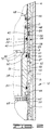
Lower housing section 16 includes a first, relatively large, outside diameter inupper region 32. Longitudinally adjacent and belowupper region 32 is first packerseal receiving groove 75. The transition betweenupper region 32 and firstpacker receiving groove 75 is relatively abrupt, formingshoulder 73. In one preferred embodiment,shoulder 73 is located on the outer surface oflower housing 16 proximate and below the location on the outer surface which corresponds to taperedtransition zone 36 on the inner surface oflower housing 16. - First annular
packer receiving groove 75 includes first and second componentannular grooves annular groove 74a is relatively wide while second componentannular groove 74b is lower, and relatively deeper. Similarly, a second packer receiving groove 76 includes a relatively wide portion 77a and lower, relatively deeper,portion 77b. Adjacent and below first annular groove 74, and aboveannular groove 77 is a firstannular ridge 78. Adjacent and below second annular groove 76 is a secondannular ridge 80. The outside diameters of first and secondannular ridges lower region 34 oflower housing 16 below secondannular ridge 80 is of a relatively reduced diameter compared to that ofupper region 32. - A
first packer cup 82 extends aroundlower mandrel 16, and is retained in firstpacker retaining groove 75.First packer cup 82 is preferably of a tapered radius, such that the diameter at the upper end offirst packer cup 82 is greater than the diameter at the lower end offirst packer cup 82.First packer cup 82 smoothly tapers from the diameter at the lower end offirst packer cup 82 to the diameter at the upper end offirst packer cup 82. Similarly, asecond packer cup 84 is retained in second packer retaining groove 76. The diameter of the upper end ofsecond packer cup 84 is similarly greater than the diameter at the lower end ofsecond packer cup 84.Second packer cup 84 smoothly tapers from the diameter at the lower end ofsecond packer cup 84 to the diameter at the upper end ofsecond packer cup 84. Packer cups 82 and 84 are each provided at their lower ends with an inwardly-extending protrusion orlip annular grooves - The operation of
multi-stage cementing tool 10 is as follows. Aftermulti-stage cementing tool 10 has been assembled, as shown in FIG. 1, the tool is inserted as a portion of a workover casing string into the borehole. The upper end offirst packer cup 82 andsecond packer cup 84 are in contact with the inner surface of the existing casing sidewalls as the workover casing string and associatedmulti-stage cementing tool 10 are lowered into the borehole. - When
multi-stage cementing tool 10 is at the desired depth, a spacer fluid is generally pumped down the workover casing string to clear mud and other debris out of the string. Such "spacer plug," may be a conventional apparatus known to the industry, typically including a mandrel with rubber wipers. The rubber wipers of the spacer plug clean the interior of the casing as the plug travels therethrough. The spacer plug also can be used to separate the spacer fluid from the first stage of cement slurry. However, the spacer plug is not required in applications where it is unimportant whether the spacer fluid and the cement slurry mix in the borehole annulus. After the spacer fluid, and the spacer plug (if a spacer plug is desired), has been pumped through the casing string, the first stage of cement slurry is pumped through the casing string, out of the bottom of the casing string and up into the surrounding annulus. - Referring now to FIGS. 2 and 3, after the first stage of cement slurry has been pumped, a sealing
plug 90 is dropped through the casing string, or is displaced behind the first stage of slurry, to engage openingseat 38. Free-fall plug 90 can be any of several plugs known to those skilled in the art. In this preferred embodiment, sealingplug 90 illustrated herein is a displacement-type plug. Sealingplug 90 includescoated body member 91, which is approximately 14 inches long.Body member 91 is provided at alower end 92 with a first, lower,centralizer 94, and at itsupper end 93 with second, upper,centralizer 95. Sealingplug 90 further includes upper andlower wipers centralizers wipers wipers wipers plug 90 also includes a generallyrigid seating block 100. - In this embodiment, the nominal diameter of
centralizer 94 is greater than the inside diameter of, or bore through, openingsleeve 38. However,centralizer 94 will flex upward as sealingplug 90 continues downward, as will wipers 96, 98. Seatingblock 100 then seats in taperedseat 60 of openingsleeve 38. Sealingplug 90 is shown depicted withseating block 100 seated in taperedseat 60 of openingsleeve 38 in FIGS. 2 and 3. Seatingblock 100 has an outside diameter less than the inner diameter of closingseat 42, to enable seating block 100 to pass through closingseat 42 and seat in taperedseat 60. - After seating
plug 90 has been dropped or displaced from the surface and has engaged and seated in taperedseat 60 of openingsleeve 38, themulti-stage cementing tool 10 is still in the configuration shown in FIG. 1. As pressure is applied in the casing string abovemulti-stage cementing tool 10, shear pins 44 of openingsleeve 38 shear and openingsleeve 38 moves down fromfirst bore section 31 and intosecond bore section 35 ofupper region 32 oflower housing 16. - As opening
sleeve 38 moves downwardly, O-ring 52passes shoulder 33 and enterssecond bore section 35. O-ring 52 does not provide a fluid-tight seal insecond bore section 35 because of the relatively enlarged diameter ofsecond bore section 35 compared to that offirst bore section 31. Openingsleeve 38 moves down until taperedregion 62 of the outer surface of openingsleeve 38 engages and seats in taperedtransition zone 36 oflower housing 16, as is shown in FIG. 2.Narrow grooves 63 provide fluid communication betweenupper housing 14 andlower region 34 oflower housing 16. With continuing reference to FIG. 2,ports 22 are exposed, thereby allowing fluid communication between the interior of the slimholemulti-stage cementing tool 10 and the borehole annulus. - At this time, the second stage of cement slurry is pumped down the tubing string and through
ports 22 inupper mandrel 14 intoannulus 24 of well bore 11. When the second stage of cement slurry has been fully pumped throughports 22, a conventional, appropriately-sized closing plug is pumped into the casing string. The closing plug engages and seats in taperedseat 68 of closingseat 42. Closingseat 42 is held in a fixed position relative toupper mandrel 14 by shear pins 46. Pressure is applied within the workover casing until the pressure exceeds the design limits of shear pins 46. Shear pins 46 then shear and closingseat 42 moves downwardly. Since closingsleeve 40 is shear-pinned to closingseat 42 byshear pins 48, closingsleeve 40 moves downward with closingseat 42. Lockingring 56 associated with closingsleeve 40 expands intoannular recess 26 ofupper housing 14 after lockingring 58passes shoulder 28 ofannular recess 26. As has already been described, narrow channels orgrooves 63 in taperedregion 62 of outer surface of openingsleeve 38 provide fluid communication betweenupper mandrel 14 andlower region 34 oflower mandrel 16. Thus, fluid is prevented from being trapped between openingsleeve 38 and closingseat 42 as closingseat 42 moves down, thereby allowing closingsleeve 40 to fully close and sealports 22. - O-
rings sleeve 40 andsecond bore section 17 ofupper housing 14 below and aboveports 22, respectively. Should a force act on closingsleeve 40 in an upward direction, lockingring 58 will engageshoulder 28 ofannular recess 26, thereby inhibiting further movement upward of closingsleeve 40. Pressure indicators at the surface will indicate when closingsleeve 40 has closedports 22 inupper mandrel 14. - When
lower lip 102 of closingsleeve 40 contactsupper edge 104 oflower housing 16, closingsleeve 40 is restrained from further movement downward. When the pressure in the casing string exceeds the design limits of shear pins 48, shear pins 48 are sheared and closingseat 42 moves downwardly untillower lip 70 of closingseat 42 contactsupper lip 64 of openingsleeve 38.Extended lug 66 of openingsleeve 38 is received inslot 72 of closingseat 42 whenupper lip 64 is in contact withlower lip 70 of closingseat 42. If either openingsleeve 38 or closingseat 42 rotate slightly during their respective downward motion,extended lug 66 will still be received inslot 72 of closingseat 42 becauseslot 72 extends further around the circumference of closingseat 42 than does extendedlug 66 extend around the circumference of openingsleeve 38. - Opening
sleeve 38 and closingseat 42 may be drilled out in a manner known to the art. Openingsleeve 38 is substantially prevented from rotation due to the force of friction between taperedtransition zone 36 inlower mandrel 16 and taperedregion 62 of openingsleeve 38. Likewise, closingseat 42 is prevented from rotating by theextended lug 66 andslot 72 combination. - If additional stages of operation are desired, inserts may be inserted inside and seated in closing
seat 42 and openingsleeve 38. Such a modified multi-stage cementing tool may then be used in conjunction withmulti-stage cementing tool 10 to facilitate pumping a third stage of cement into the annulus between the casing string and the existing casing string or well-bore. The modified tool is inserted in the casing string below slimholemulti-stage cementing tool 10. A set of plugs having a relatively reduced outside diameter are used to actuate the modified slimhole multi-stage cementing tool. Then, slimholemulti-stage cementing tool 10 without modifications is actuated as discussed above.
Claims (9)
- An apparatus (10) for cementing multiple stages within a well, which apparatus comprises a housing assembly (12), said housing assembly having at least one port (22) therein; a first sleeve (38) retained within said housing (12), said sleeve (38) being movable from a first position covering said port (22) to a second position opening said port (22); a second sleeve assembly (39), said sleeve assembly (39) being movable from a first position away from said port (22) to a second position covering said port (22); said housing assembly (12) further comprising an inwardly extending tapered shoulder (36), and said first sleeve (38) comprising a tapered surface (62), said tapered shoulder (36) and said tapered surface (62) being cooperatively engageable such that engagement of said tapered surface (62) with said tapered shoulder (36) establishes said second position of said first sleeve (38) and such that said engagement of said tapered surface (62) with said tapered shoulder (36) inhibits relation of said first sleeve (38) relative to said housing assembly (12).
- Apparatus according to claim 1, wherein the angle of taper of said tapered shoulder (36) of said housing assembly (12) is different from the angle of taper of said tapered surface (62) of said first sleeve (38).
- Apparatus according to claim 1 or 2, wherein said first sleeve (38) and said second sleeve assembly (39) are configured to be cooperatively engageable to establish a limited range of rotation between said first sleeve (38) and at least a portion of said second sleeve assembly (39) when said first sleeve (38) is in said second position, and wherein said portion of said second sleeve assembly(39) is further in said second position.
- Apparatus according to claim 1,2 or 3, wherein said second sleeve assembly (39) comprises a sealing sleeve (40) and an actuation sleeve (42), said actuation sleeve (42) being releasably coupled to said sealing sleeve (40).
- Apparatus according to claim 4, wherein said actuation sleeve (42) is cooperatively configured with said first sleeve (38) to establish a limited range of relative rotation therewith when said actuation sleeve (42) and said first sleeve (38) are in said first, unactuated, positions.
- Apparatus according to claim 5, wherein said actuation sleeve (42) and said first sleeve (38) are also cooperatively engageable when each said sleeve is in its respective second position.
- Apparatus according to any of claims 1 to 6, wherein at least one of said tapered shoulder (36) and said tapered surface (62) include a groove (63) to allow fluid passage between said two members.
- A system for cementing multiple stages within a well, which system comprises a cementing valve assembly which valve assembly comprises a housing assembly (12) defining at least one radial port (22); a first sleeve assembly (38), slightly retained within said housing (12) for longitudinal movement relative thereto, said sleeve (38) being movable from a first position substantially covering said port (22) to a second position substantially opening said port (22); a second sleeve assembly (39) retained within said housing (12) for longitudinal movement relative thereto, said second sleeve assembly (39) comprising a sealing sleeve (40) and an actuation sleeve (42), said sealing sleeve (40) being releasably coupled to said actuation sleeve (42), said second sleeve assembly (39) being movable from a first position wherein said sealing sleeve (40) is longitudinally above said port (22), to a second position wherein said sealing sleeve (40) is substantially adjacent to and covering said port (22); said housing (12) defining a generally radially extending engagement surface (36), and said first sleeve (38) including a tapered wedging surface (62), said surfaces being cooperatively configured to establish a wedging engagement between said first sleeve (38) and said housing assembly (12) when said first sleeve (38) is moved to said second position; and a first plug member (90) which is selectively engageable with said first sleeve (38) and adapted to block the flow fluid relative to said first sleeve (38) such that the application of pressure above said first sleeve (38) will cause movement of said first sleeve (38) from said first position to said second position.
- A system according to claim 8, wherein said actuation sleeve (42) is further movable to a third position relative to said housing assembly, and wherein said actuation sleeve (42) and said first sleeve (38) are cooperatively conformed to establish rotation limiting engagement between said actuation sleeve (42) and said first sleeve (38) when said first sleeve (38) is in said second position and said actuation sleeve (42) is in said third position.
Applications Claiming Priority (2)
| Application Number | Priority Date | Filing Date | Title |
|---|---|---|---|
| US08/107,486 US5348089A (en) | 1993-08-17 | 1993-08-17 | Method and apparatus for the multiple stage cementing of a casing string in a well |
| US107486 | 1993-08-17 |
Publications (2)
| Publication Number | Publication Date |
|---|---|
| EP0639689A2 true EP0639689A2 (en) | 1995-02-22 |
| EP0639689A3 EP0639689A3 (en) | 1995-07-26 |
Family
ID=22316876
Family Applications (1)
| Application Number | Title | Priority Date | Filing Date |
|---|---|---|---|
| EP94304412A Withdrawn EP0639689A3 (en) | 1993-08-17 | 1994-06-17 | Multiple stage well cementing apparatus. |
Country Status (5)
| Country | Link |
|---|---|
| US (1) | US5348089A (en) |
| EP (1) | EP0639689A3 (en) |
| AU (1) | AU6470594A (en) |
| CA (1) | CA2130302A1 (en) |
| NO (1) | NO942417L (en) |
Cited By (4)
| Publication number | Priority date | Publication date | Assignee | Title |
|---|---|---|---|---|
| US7748463B2 (en) | 2006-01-20 | 2010-07-06 | Peak Well Solutions As | Cementing valve |
| GB2522264A (en) * | 2014-01-21 | 2015-07-22 | Swellfix Bv | Sliding Sleeve Tool |
| CN110984904A (en) * | 2019-10-29 | 2020-04-10 | 东北大学 | Air pressure type separation high-pressure liquid injection device and method for complex fractured rock mass |
| WO2022231722A1 (en) * | 2021-04-29 | 2022-11-03 | Halliburton Energy Services, Inc. | Stage cementer packer |
Families Citing this family (18)
| Publication number | Priority date | Publication date | Assignee | Title |
|---|---|---|---|---|
| US5526878A (en) * | 1995-02-06 | 1996-06-18 | Halliburton Company | Stage cementer with integral inflation packer |
| US5738171A (en) * | 1997-01-09 | 1998-04-14 | Halliburton Company | Well cementing inflation packer tools and methods |
| US5957197A (en) * | 1997-04-10 | 1999-09-28 | Liaohe Petroleum Exploration Bureau Of Xinglongtai | Downhole cut-off valve used for cementing |
| US6651743B2 (en) * | 2001-05-24 | 2003-11-25 | Halliburton Energy Services, Inc. | Slim hole stage cementer and method |
| US7540325B2 (en) * | 2005-03-14 | 2009-06-02 | Presssol Ltd. | Well cementing apparatus and method |
| US20070068703A1 (en) * | 2005-07-19 | 2007-03-29 | Tesco Corporation | Method for drilling and cementing a well |
| WO2007134255A2 (en) * | 2006-05-12 | 2007-11-22 | Weatherford/Lamb, Inc. | Stage cementing methods used in casing while drilling |
| US7472752B2 (en) * | 2007-01-09 | 2009-01-06 | Halliburton Energy Services, Inc. | Apparatus and method for forming multiple plugs in a wellbore |
| US8800655B1 (en) * | 2010-02-01 | 2014-08-12 | Michael E. Bailey | Stage cementing tool |
| US20140251628A1 (en) * | 2013-03-08 | 2014-09-11 | James F. Wilkin | Anti-Rotation Assembly for Sliding Sleeve |
| US9394760B2 (en) * | 2013-08-02 | 2016-07-19 | Halliburton Energy Services, Inc. | Clutch apparatus and method for resisting torque |
| US9970258B2 (en) | 2014-05-16 | 2018-05-15 | Weatherford Technology Holdings, Llc | Remotely operated stage cementing methods for liner drilling installations |
| US9816351B2 (en) | 2014-11-14 | 2017-11-14 | Antelope Oil Tool & Mfg. Co. | Multi-stage cementing tool and method |
| WO2020040656A1 (en) | 2018-08-24 | 2020-02-27 | Schlumberger Canada Limited | Systems and methods for horizontal well completions |
| US11391117B2 (en) * | 2019-07-08 | 2022-07-19 | Halliburton Energy Services, Inc. | Annular casing packer collar stage tool for cementing operations |
| RU2741882C1 (en) * | 2020-11-12 | 2021-01-29 | Открытое акционерное общество «Тяжпрессмаш» | Method for multi-stage cuff cementing of wells |
| US11306562B1 (en) * | 2021-04-28 | 2022-04-19 | Weatherford Technology Holdings, Llc | Stage tool having composite seats |
| US11686182B2 (en) * | 2021-10-19 | 2023-06-27 | Weatherford Technology Holdings, Llc | Top-down cementing of liner assembly |
Citations (5)
| Publication number | Priority date | Publication date | Assignee | Title |
|---|---|---|---|---|
| US2998075A (en) * | 1957-07-29 | 1961-08-29 | Baker Oil Tools Inc | Subsurface well apparatus |
| US3768556A (en) * | 1972-05-10 | 1973-10-30 | Halliburton Co | Cementing tool |
| US3791448A (en) * | 1972-12-11 | 1974-02-12 | Atlantic Richfield Co | Well completion method |
| US3948322A (en) * | 1975-04-23 | 1976-04-06 | Halliburton Company | Multiple stage cementing tool with inflation packer and methods of use |
| US5109925A (en) * | 1991-01-17 | 1992-05-05 | Halliburton Company | Multiple stage inflation packer with secondary opening rupture disc |
Family Cites Families (6)
| Publication number | Priority date | Publication date | Assignee | Title |
|---|---|---|---|---|
| US3228473A (en) * | 1962-11-28 | 1966-01-11 | Halliburton Co | Cementing collar and means for actuating same |
| US3789926A (en) * | 1972-10-19 | 1974-02-05 | R Henley | Two stage cementing collar |
| US4246968A (en) * | 1979-10-17 | 1981-01-27 | Halliburton Company | Cementing tool with protective sleeve |
| US4260017A (en) * | 1979-11-13 | 1981-04-07 | The Dow Chemical Company | Cementing collar and method of operation |
| US4479545A (en) * | 1982-10-27 | 1984-10-30 | Eley Fred N | Well-cementing stage collar |
| US5137087A (en) * | 1991-08-07 | 1992-08-11 | Halliburton Company | Casing cementer with torque-limiting rotating positioning tool |
-
1993
- 1993-08-17 US US08/107,486 patent/US5348089A/en not_active Expired - Lifetime
-
1994
- 1994-06-15 AU AU64705/94A patent/AU6470594A/en not_active Abandoned
- 1994-06-17 EP EP94304412A patent/EP0639689A3/en not_active Withdrawn
- 1994-06-24 NO NO942417A patent/NO942417L/en unknown
- 1994-08-17 CA CA002130302A patent/CA2130302A1/en not_active Abandoned
Patent Citations (5)
| Publication number | Priority date | Publication date | Assignee | Title |
|---|---|---|---|---|
| US2998075A (en) * | 1957-07-29 | 1961-08-29 | Baker Oil Tools Inc | Subsurface well apparatus |
| US3768556A (en) * | 1972-05-10 | 1973-10-30 | Halliburton Co | Cementing tool |
| US3791448A (en) * | 1972-12-11 | 1974-02-12 | Atlantic Richfield Co | Well completion method |
| US3948322A (en) * | 1975-04-23 | 1976-04-06 | Halliburton Company | Multiple stage cementing tool with inflation packer and methods of use |
| US5109925A (en) * | 1991-01-17 | 1992-05-05 | Halliburton Company | Multiple stage inflation packer with secondary opening rupture disc |
Cited By (5)
| Publication number | Priority date | Publication date | Assignee | Title |
|---|---|---|---|---|
| US7748463B2 (en) | 2006-01-20 | 2010-07-06 | Peak Well Solutions As | Cementing valve |
| GB2522264A (en) * | 2014-01-21 | 2015-07-22 | Swellfix Bv | Sliding Sleeve Tool |
| CN110984904A (en) * | 2019-10-29 | 2020-04-10 | 东北大学 | Air pressure type separation high-pressure liquid injection device and method for complex fractured rock mass |
| CN110984904B (en) * | 2019-10-29 | 2021-06-18 | 东北大学 | Air pressure type separation high-pressure liquid injection device and method for complex fractured rock mass |
| WO2022231722A1 (en) * | 2021-04-29 | 2022-11-03 | Halliburton Energy Services, Inc. | Stage cementer packer |
Also Published As
| Publication number | Publication date |
|---|---|
| CA2130302A1 (en) | 1995-02-18 |
| AU6470594A (en) | 1995-03-02 |
| EP0639689A3 (en) | 1995-07-26 |
| NO942417D0 (en) | 1994-06-24 |
| US5348089A (en) | 1994-09-20 |
| NO942417L (en) | 1995-02-20 |
Similar Documents
| Publication | Publication Date | Title |
|---|---|---|
| US5348089A (en) | Method and apparatus for the multiple stage cementing of a casing string in a well | |
| US6267181B1 (en) | Method and apparatus for cementing a well | |
| US4246968A (en) | Cementing tool with protective sleeve | |
| US5871050A (en) | Well completion method | |
| US3948322A (en) | Multiple stage cementing tool with inflation packer and methods of use | |
| EP0633391B1 (en) | Sliding sleeve casing tool | |
| EP0774564B1 (en) | Well casing fill apparatus and method | |
| US5738171A (en) | Well cementing inflation packer tools and methods | |
| US5368098A (en) | Stage tool | |
| US5314015A (en) | Stage cementer and inflation packer apparatus | |
| US5117910A (en) | Packer for use in, and method of, cementing a tubing string in a well without drillout | |
| US5641023A (en) | Shifting tool for a subterranean completion structure | |
| US3768556A (en) | Cementing tool | |
| US5413172A (en) | Sub-surface release plug assembly with non-metallic components | |
| EP0618345A1 (en) | Method and apparatus for cementing a casing string | |
| US5372201A (en) | Annulus pressure actuated casing hanger running tool | |
| US5330000A (en) | Squeeze packer latch | |
| CA2276522C (en) | Drill string diverter apparatus and method | |
| US4250966A (en) | Insertion type cementing baffle | |
| US5226478A (en) | Cement port closure sleeve for a subsea well | |
| AU2005311155B2 (en) | Diverter tool | |
| SU1765367A1 (en) | Casing stepped cementation sleeve | |
| AU2018411293A1 (en) | Downhole check valve assembly with a ratchet mechanism | |
| US20230167711A1 (en) | Downhole degradable staging tool | |
| CA3140892A1 (en) | Downhole degradable staging tool |
Legal Events
| Date | Code | Title | Description |
|---|---|---|---|
| PUAI | Public reference made under article 153(3) epc to a published international application that has entered the european phase |
Free format text: ORIGINAL CODE: 0009012 |
|
| AK | Designated contracting states |
Kind code of ref document: A2 Designated state(s): DE DK ES FR GB IT NL |
|
| PUAL | Search report despatched |
Free format text: ORIGINAL CODE: 0009013 |
|
| AK | Designated contracting states |
Kind code of ref document: A3 Designated state(s): DE DK ES FR GB IT NL |
|
| STAA | Information on the status of an ep patent application or granted ep patent |
Free format text: STATUS: THE APPLICATION IS DEEMED TO BE WITHDRAWN |
|
| 18D | Application deemed to be withdrawn |
Effective date: 19960127 |