EP0639356A1 - Verfahren zur Erzeugung von äusseren Verankerungsflächen an Gelenkimplantaten - Google Patents
Verfahren zur Erzeugung von äusseren Verankerungsflächen an Gelenkimplantaten Download PDFInfo
- Publication number
- EP0639356A1 EP0639356A1 EP93810583A EP93810583A EP0639356A1 EP 0639356 A1 EP0639356 A1 EP 0639356A1 EP 93810583 A EP93810583 A EP 93810583A EP 93810583 A EP93810583 A EP 93810583A EP 0639356 A1 EP0639356 A1 EP 0639356A1
- Authority
- EP
- European Patent Office
- Prior art keywords
- shoulders
- shell
- blank
- anchoring
- shoulder
- Prior art date
- Legal status (The legal status is an assumption and is not a legal conclusion. Google has not performed a legal analysis and makes no representation as to the accuracy of the status listed.)
- Granted
Links
- 238000000034 method Methods 0.000 title claims abstract description 14
- 239000007943 implant Substances 0.000 title claims abstract description 13
- 238000004873 anchoring Methods 0.000 title claims description 54
- 238000007493 shaping process Methods 0.000 title description 3
- 238000003780 insertion Methods 0.000 claims abstract description 52
- 230000037431 insertion Effects 0.000 claims abstract description 52
- 238000003825 pressing Methods 0.000 claims abstract description 16
- 238000005266 casting Methods 0.000 claims abstract description 5
- 238000003754 machining Methods 0.000 claims abstract description 5
- 210000004394 hip joint Anatomy 0.000 claims description 12
- 238000004519 manufacturing process Methods 0.000 claims description 8
- RTAQQCXQSZGOHL-UHFFFAOYSA-N Titanium Chemical compound [Ti] RTAQQCXQSZGOHL-UHFFFAOYSA-N 0.000 claims description 4
- 239000010936 titanium Substances 0.000 claims description 4
- 229910052719 titanium Inorganic materials 0.000 claims description 4
- 229910052751 metal Inorganic materials 0.000 claims description 3
- 239000002184 metal Substances 0.000 claims description 3
- 229910000831 Steel Inorganic materials 0.000 claims description 2
- 238000013459 approach Methods 0.000 claims description 2
- 238000012545 processing Methods 0.000 claims description 2
- 239000010959 steel Substances 0.000 claims description 2
- 230000001154 acute effect Effects 0.000 claims 1
- 210000003049 pelvic bone Anatomy 0.000 claims 1
- 210000000988 bone and bone Anatomy 0.000 description 10
- 238000007514 turning Methods 0.000 description 4
- 210000000689 upper leg Anatomy 0.000 description 4
- 210000000629 knee joint Anatomy 0.000 description 3
- 239000000463 material Substances 0.000 description 2
- 230000013011 mating Effects 0.000 description 2
- 238000002271 resection Methods 0.000 description 2
- 208000000260 Warts Diseases 0.000 description 1
- 238000005520 cutting process Methods 0.000 description 1
- 238000013461 design Methods 0.000 description 1
- 238000006073 displacement reaction Methods 0.000 description 1
- 238000009760 electrical discharge machining Methods 0.000 description 1
- 230000002349 favourable effect Effects 0.000 description 1
- 238000010438 heat treatment Methods 0.000 description 1
- 238000002513 implantation Methods 0.000 description 1
- 210000003127 knee Anatomy 0.000 description 1
- 201000010153 skin papilloma Diseases 0.000 description 1
- 238000004018 waxing Methods 0.000 description 1
Images

Classifications
-
- B—PERFORMING OPERATIONS; TRANSPORTING
- B21—MECHANICAL METAL-WORKING WITHOUT ESSENTIALLY REMOVING MATERIAL; PUNCHING METAL
- B21D—WORKING OR PROCESSING OF SHEET METAL OR METAL TUBES, RODS OR PROFILES WITHOUT ESSENTIALLY REMOVING MATERIAL; PUNCHING METAL
- B21D31/00—Other methods for working sheet metal, metal tubes, metal profiles
-
- A—HUMAN NECESSITIES
- A61—MEDICAL OR VETERINARY SCIENCE; HYGIENE
- A61F—FILTERS IMPLANTABLE INTO BLOOD VESSELS; PROSTHESES; DEVICES PROVIDING PATENCY TO, OR PREVENTING COLLAPSING OF, TUBULAR STRUCTURES OF THE BODY, e.g. STENTS; ORTHOPAEDIC, NURSING OR CONTRACEPTIVE DEVICES; FOMENTATION; TREATMENT OR PROTECTION OF EYES OR EARS; BANDAGES, DRESSINGS OR ABSORBENT PADS; FIRST-AID KITS
- A61F2/00—Filters implantable into blood vessels; Prostheses, i.e. artificial substitutes or replacements for parts of the body; Appliances for connecting them with the body; Devices providing patency to, or preventing collapsing of, tubular structures of the body, e.g. stents
- A61F2/02—Prostheses implantable into the body
- A61F2/30—Joints
- A61F2/30767—Special external or bone-contacting surface, e.g. coating for improving bone ingrowth
- A61F2/30771—Special external or bone-contacting surface, e.g. coating for improving bone ingrowth applied in original prostheses, e.g. holes or grooves
-
- A—HUMAN NECESSITIES
- A61—MEDICAL OR VETERINARY SCIENCE; HYGIENE
- A61F—FILTERS IMPLANTABLE INTO BLOOD VESSELS; PROSTHESES; DEVICES PROVIDING PATENCY TO, OR PREVENTING COLLAPSING OF, TUBULAR STRUCTURES OF THE BODY, e.g. STENTS; ORTHOPAEDIC, NURSING OR CONTRACEPTIVE DEVICES; FOMENTATION; TREATMENT OR PROTECTION OF EYES OR EARS; BANDAGES, DRESSINGS OR ABSORBENT PADS; FIRST-AID KITS
- A61F2/00—Filters implantable into blood vessels; Prostheses, i.e. artificial substitutes or replacements for parts of the body; Appliances for connecting them with the body; Devices providing patency to, or preventing collapsing of, tubular structures of the body, e.g. stents
- A61F2/02—Prostheses implantable into the body
- A61F2/30—Joints
- A61F2/32—Joints for the hip
- A61F2/34—Acetabular cups
-
- A—HUMAN NECESSITIES
- A61—MEDICAL OR VETERINARY SCIENCE; HYGIENE
- A61F—FILTERS IMPLANTABLE INTO BLOOD VESSELS; PROSTHESES; DEVICES PROVIDING PATENCY TO, OR PREVENTING COLLAPSING OF, TUBULAR STRUCTURES OF THE BODY, e.g. STENTS; ORTHOPAEDIC, NURSING OR CONTRACEPTIVE DEVICES; FOMENTATION; TREATMENT OR PROTECTION OF EYES OR EARS; BANDAGES, DRESSINGS OR ABSORBENT PADS; FIRST-AID KITS
- A61F2/00—Filters implantable into blood vessels; Prostheses, i.e. artificial substitutes or replacements for parts of the body; Appliances for connecting them with the body; Devices providing patency to, or preventing collapsing of, tubular structures of the body, e.g. stents
- A61F2/02—Prostheses implantable into the body
- A61F2/30—Joints
- A61F2/3094—Designing or manufacturing processes
-
- A—HUMAN NECESSITIES
- A61—MEDICAL OR VETERINARY SCIENCE; HYGIENE
- A61F—FILTERS IMPLANTABLE INTO BLOOD VESSELS; PROSTHESES; DEVICES PROVIDING PATENCY TO, OR PREVENTING COLLAPSING OF, TUBULAR STRUCTURES OF THE BODY, e.g. STENTS; ORTHOPAEDIC, NURSING OR CONTRACEPTIVE DEVICES; FOMENTATION; TREATMENT OR PROTECTION OF EYES OR EARS; BANDAGES, DRESSINGS OR ABSORBENT PADS; FIRST-AID KITS
- A61F2/00—Filters implantable into blood vessels; Prostheses, i.e. artificial substitutes or replacements for parts of the body; Appliances for connecting them with the body; Devices providing patency to, or preventing collapsing of, tubular structures of the body, e.g. stents
- A61F2/02—Prostheses implantable into the body
- A61F2/30—Joints
- A61F2/38—Joints for elbows or knees
- A61F2/3859—Femoral components
-
- A—HUMAN NECESSITIES
- A61—MEDICAL OR VETERINARY SCIENCE; HYGIENE
- A61F—FILTERS IMPLANTABLE INTO BLOOD VESSELS; PROSTHESES; DEVICES PROVIDING PATENCY TO, OR PREVENTING COLLAPSING OF, TUBULAR STRUCTURES OF THE BODY, e.g. STENTS; ORTHOPAEDIC, NURSING OR CONTRACEPTIVE DEVICES; FOMENTATION; TREATMENT OR PROTECTION OF EYES OR EARS; BANDAGES, DRESSINGS OR ABSORBENT PADS; FIRST-AID KITS
- A61F2/00—Filters implantable into blood vessels; Prostheses, i.e. artificial substitutes or replacements for parts of the body; Appliances for connecting them with the body; Devices providing patency to, or preventing collapsing of, tubular structures of the body, e.g. stents
- A61F2/02—Prostheses implantable into the body
- A61F2/30—Joints
- A61F2/46—Special tools for implanting artificial joints
- A61F2/4603—Special tools for implanting artificial joints for insertion or extraction of endoprosthetic joints or of accessories thereof
- A61F2/4609—Special tools for implanting artificial joints for insertion or extraction of endoprosthetic joints or of accessories thereof of acetabular cups
-
- A—HUMAN NECESSITIES
- A61—MEDICAL OR VETERINARY SCIENCE; HYGIENE
- A61F—FILTERS IMPLANTABLE INTO BLOOD VESSELS; PROSTHESES; DEVICES PROVIDING PATENCY TO, OR PREVENTING COLLAPSING OF, TUBULAR STRUCTURES OF THE BODY, e.g. STENTS; ORTHOPAEDIC, NURSING OR CONTRACEPTIVE DEVICES; FOMENTATION; TREATMENT OR PROTECTION OF EYES OR EARS; BANDAGES, DRESSINGS OR ABSORBENT PADS; FIRST-AID KITS
- A61F2/00—Filters implantable into blood vessels; Prostheses, i.e. artificial substitutes or replacements for parts of the body; Appliances for connecting them with the body; Devices providing patency to, or preventing collapsing of, tubular structures of the body, e.g. stents
- A61F2/02—Prostheses implantable into the body
- A61F2/30—Joints
- A61F2002/30001—Additional features of subject-matter classified in A61F2/28, A61F2/30 and subgroups thereof
- A61F2002/30108—Shapes
- A61F2002/3011—Cross-sections or two-dimensional shapes
- A61F2002/30112—Rounded shapes, e.g. with rounded corners
- A61F2002/30113—Rounded shapes, e.g. with rounded corners circular
- A61F2002/30118—Rounded shapes, e.g. with rounded corners circular concentric circles
-
- A—HUMAN NECESSITIES
- A61—MEDICAL OR VETERINARY SCIENCE; HYGIENE
- A61F—FILTERS IMPLANTABLE INTO BLOOD VESSELS; PROSTHESES; DEVICES PROVIDING PATENCY TO, OR PREVENTING COLLAPSING OF, TUBULAR STRUCTURES OF THE BODY, e.g. STENTS; ORTHOPAEDIC, NURSING OR CONTRACEPTIVE DEVICES; FOMENTATION; TREATMENT OR PROTECTION OF EYES OR EARS; BANDAGES, DRESSINGS OR ABSORBENT PADS; FIRST-AID KITS
- A61F2/00—Filters implantable into blood vessels; Prostheses, i.e. artificial substitutes or replacements for parts of the body; Appliances for connecting them with the body; Devices providing patency to, or preventing collapsing of, tubular structures of the body, e.g. stents
- A61F2/02—Prostheses implantable into the body
- A61F2/30—Joints
- A61F2002/30001—Additional features of subject-matter classified in A61F2/28, A61F2/30 and subgroups thereof
- A61F2002/30316—The prosthesis having different structural features at different locations within the same prosthesis; Connections between prosthetic parts; Special structural features of bone or joint prostheses not otherwise provided for
- A61F2002/30329—Connections or couplings between prosthetic parts, e.g. between modular parts; Connecting elements
- A61F2002/30476—Connections or couplings between prosthetic parts, e.g. between modular parts; Connecting elements locked by an additional locking mechanism
- A61F2002/305—Snap connection
-
- A—HUMAN NECESSITIES
- A61—MEDICAL OR VETERINARY SCIENCE; HYGIENE
- A61F—FILTERS IMPLANTABLE INTO BLOOD VESSELS; PROSTHESES; DEVICES PROVIDING PATENCY TO, OR PREVENTING COLLAPSING OF, TUBULAR STRUCTURES OF THE BODY, e.g. STENTS; ORTHOPAEDIC, NURSING OR CONTRACEPTIVE DEVICES; FOMENTATION; TREATMENT OR PROTECTION OF EYES OR EARS; BANDAGES, DRESSINGS OR ABSORBENT PADS; FIRST-AID KITS
- A61F2/00—Filters implantable into blood vessels; Prostheses, i.e. artificial substitutes or replacements for parts of the body; Appliances for connecting them with the body; Devices providing patency to, or preventing collapsing of, tubular structures of the body, e.g. stents
- A61F2/02—Prostheses implantable into the body
- A61F2/30—Joints
- A61F2/30767—Special external or bone-contacting surface, e.g. coating for improving bone ingrowth
- A61F2/30771—Special external or bone-contacting surface, e.g. coating for improving bone ingrowth applied in original prostheses, e.g. holes or grooves
- A61F2002/30878—Special external or bone-contacting surface, e.g. coating for improving bone ingrowth applied in original prostheses, e.g. holes or grooves with non-sharp protrusions, for instance contacting the bone for anchoring, e.g. keels, pegs, pins, posts, shanks, stems, struts
- A61F2002/30879—Ribs
-
- A—HUMAN NECESSITIES
- A61—MEDICAL OR VETERINARY SCIENCE; HYGIENE
- A61F—FILTERS IMPLANTABLE INTO BLOOD VESSELS; PROSTHESES; DEVICES PROVIDING PATENCY TO, OR PREVENTING COLLAPSING OF, TUBULAR STRUCTURES OF THE BODY, e.g. STENTS; ORTHOPAEDIC, NURSING OR CONTRACEPTIVE DEVICES; FOMENTATION; TREATMENT OR PROTECTION OF EYES OR EARS; BANDAGES, DRESSINGS OR ABSORBENT PADS; FIRST-AID KITS
- A61F2/00—Filters implantable into blood vessels; Prostheses, i.e. artificial substitutes or replacements for parts of the body; Appliances for connecting them with the body; Devices providing patency to, or preventing collapsing of, tubular structures of the body, e.g. stents
- A61F2/02—Prostheses implantable into the body
- A61F2/30—Joints
- A61F2/30767—Special external or bone-contacting surface, e.g. coating for improving bone ingrowth
- A61F2/30771—Special external or bone-contacting surface, e.g. coating for improving bone ingrowth applied in original prostheses, e.g. holes or grooves
- A61F2002/30878—Special external or bone-contacting surface, e.g. coating for improving bone ingrowth applied in original prostheses, e.g. holes or grooves with non-sharp protrusions, for instance contacting the bone for anchoring, e.g. keels, pegs, pins, posts, shanks, stems, struts
- A61F2002/30891—Plurality of protrusions
- A61F2002/30892—Plurality of protrusions parallel
-
- A—HUMAN NECESSITIES
- A61—MEDICAL OR VETERINARY SCIENCE; HYGIENE
- A61F—FILTERS IMPLANTABLE INTO BLOOD VESSELS; PROSTHESES; DEVICES PROVIDING PATENCY TO, OR PREVENTING COLLAPSING OF, TUBULAR STRUCTURES OF THE BODY, e.g. STENTS; ORTHOPAEDIC, NURSING OR CONTRACEPTIVE DEVICES; FOMENTATION; TREATMENT OR PROTECTION OF EYES OR EARS; BANDAGES, DRESSINGS OR ABSORBENT PADS; FIRST-AID KITS
- A61F2/00—Filters implantable into blood vessels; Prostheses, i.e. artificial substitutes or replacements for parts of the body; Appliances for connecting them with the body; Devices providing patency to, or preventing collapsing of, tubular structures of the body, e.g. stents
- A61F2/02—Prostheses implantable into the body
- A61F2/30—Joints
- A61F2/32—Joints for the hip
- A61F2/34—Acetabular cups
- A61F2002/3401—Acetabular cups with radial apertures, e.g. radial bores for receiving fixation screws
- A61F2002/3403—Polar aperture
-
- A—HUMAN NECESSITIES
- A61—MEDICAL OR VETERINARY SCIENCE; HYGIENE
- A61F—FILTERS IMPLANTABLE INTO BLOOD VESSELS; PROSTHESES; DEVICES PROVIDING PATENCY TO, OR PREVENTING COLLAPSING OF, TUBULAR STRUCTURES OF THE BODY, e.g. STENTS; ORTHOPAEDIC, NURSING OR CONTRACEPTIVE DEVICES; FOMENTATION; TREATMENT OR PROTECTION OF EYES OR EARS; BANDAGES, DRESSINGS OR ABSORBENT PADS; FIRST-AID KITS
- A61F2/00—Filters implantable into blood vessels; Prostheses, i.e. artificial substitutes or replacements for parts of the body; Appliances for connecting them with the body; Devices providing patency to, or preventing collapsing of, tubular structures of the body, e.g. stents
- A61F2/02—Prostheses implantable into the body
- A61F2/30—Joints
- A61F2/32—Joints for the hip
- A61F2/34—Acetabular cups
- A61F2002/3453—Acetabular cups having a non-hemispherical convex outer surface, e.g. quadric-shaped
- A61F2002/3456—Acetabular cups having a non-hemispherical convex outer surface, e.g. quadric-shaped ellipsoidal or having a flattened polar region
-
- A—HUMAN NECESSITIES
- A61—MEDICAL OR VETERINARY SCIENCE; HYGIENE
- A61F—FILTERS IMPLANTABLE INTO BLOOD VESSELS; PROSTHESES; DEVICES PROVIDING PATENCY TO, OR PREVENTING COLLAPSING OF, TUBULAR STRUCTURES OF THE BODY, e.g. STENTS; ORTHOPAEDIC, NURSING OR CONTRACEPTIVE DEVICES; FOMENTATION; TREATMENT OR PROTECTION OF EYES OR EARS; BANDAGES, DRESSINGS OR ABSORBENT PADS; FIRST-AID KITS
- A61F2230/00—Geometry of prostheses classified in groups A61F2/00 - A61F2/26 or A61F2/82 or A61F9/00 or A61F11/00 or subgroups thereof
- A61F2230/0002—Two-dimensional shapes, e.g. cross-sections
- A61F2230/0004—Rounded shapes, e.g. with rounded corners
- A61F2230/0006—Rounded shapes, e.g. with rounded corners circular
-
- A—HUMAN NECESSITIES
- A61—MEDICAL OR VETERINARY SCIENCE; HYGIENE
- A61F—FILTERS IMPLANTABLE INTO BLOOD VESSELS; PROSTHESES; DEVICES PROVIDING PATENCY TO, OR PREVENTING COLLAPSING OF, TUBULAR STRUCTURES OF THE BODY, e.g. STENTS; ORTHOPAEDIC, NURSING OR CONTRACEPTIVE DEVICES; FOMENTATION; TREATMENT OR PROTECTION OF EYES OR EARS; BANDAGES, DRESSINGS OR ABSORBENT PADS; FIRST-AID KITS
- A61F2310/00—Prostheses classified in A61F2/28 or A61F2/30 - A61F2/44 being constructed from or coated with a particular material
- A61F2310/00005—The prosthesis being constructed from a particular material
- A61F2310/00011—Metals or alloys
- A61F2310/00023—Titanium or titanium-based alloys, e.g. Ti-Ni alloys
Definitions
- the invention relates to a method for producing outer anchoring surfaces on joint implants from a plastically deformable metal, the anchoring surfaces being at an angle ⁇ between 0 and 90 degrees to a direction of insertion and fastening of the joint implant.
- Joint implants have to take forces in different directions on their anchoring surfaces to the bone tissue.
- the anchoring surfaces should therefore be able to transmit forces in as many directions as possible without loosening from the implant.
- various textures for anchoring surfaces were developed.
- EP 0 186 471 shows a knee joint prosthesis with sawtooth-like grooves which are arranged transversely to the direction of insertion, the stability in the direction of the grooves being reduced.
- Another alternative provides barb-like pins on the prosthesis, which penetrate into the femoral stump in the direction of insertion.
- a general requirement for anchorage areas of this type is that they should have a structure that is conducive to ingrowth and that they should be economically producible.
- DE 29 14 513 shows anchoring surfaces that are provided with wart-like projections and depressions to improve ingrowth. No information is given on the generation and the absolute dimensions of this structure. In the relative geometric relationships, rounded shapes are proposed that only allow a limited primary anchoring.
- a further structure is proposed in EP 0 381 351, in which a type of rimmed anchoring surface with flattened protruding pyramids is produced on a hip joint shell on a bulge projecting outwards by recesses which run obliquely to the equator and are offset in the circumferential direction and intersect in the circumferential direction.
- the primary anchorage is limited, that is, it depends very much on the prestress in the bone cavity or on the undersize of the bone cavity in the area of the equator.
- the object of the invention is to provide anchoring surfaces in which a good anchoring can be achieved with an inexpensive manufacturing process.
- This object is achieved in that, in a step I, punches are made in the anchoring surfaces in the anchoring surfaces transversely to the direction of insertion and fastening by machining, casting or pressing, so that acute-angled shoulders remain which have a height of between 0.3 and 2 mm, while the distance between two adjacent shoulder tips corresponds approximately to the amount of twice the height, and that in a step II the blank with a pressing tool, the base of which corresponds to the envelope surface on the anchoring surfaces of the blank and ribs projecting from the base thereof, which with their The central planes run perpendicular to the base area and parallel to the direction of insertion and fastening, and are deformed by pressing in the direction of insertion and fastening to such an extent that trenches are created with the ribs transversely to the shoulders, which leave shoulder sections, the shoulder edges are plastically deformed in the region of the trenches counter to the direction
- the invention has the advantage that complex shapes which are particularly suitable for anchoring in the bone tissue and which are hardly achievable with other methods can be produced by a geometry on the anchoring surfaces prepared for the plastic deformation and a subsequent deformation using simple means. Relative to the direction of insertion and fastening, a large number of cups are produced on the anchoring surfaces, which are at an angle ⁇ between 0 and 90 degrees to the direction of insertion and fastening.
- the individual cup is opened like the cup of a Pelton wheel against the direction of insertion and attachment. It is supported with the hollow inside in the bone tissue against the direction of insertion and attachment.
- the curved inner surface of the cup and the trenches formed between the cups with the production of the cup shape prevent the anchoring surface from sliding sideways transversely to the direction of insertion and fastening.
- the absolute dimensions of the cup shape are selected so that the pre-stressed bone tissue deforms into the areas between the cups in order to achieve good primary anchoring against the direction of insertion and attachment.
- the distances between the shoulders correspond to approximately twice their height and that the shoulders are acute-angled in cross-section, they can be plastically deformed in the transverse direction, ie counter to the direction of insertion and fastening, in order to produce cup shapes. It is important that the height of the shoulders is between 0.3 and 2 mm in order to obtain a size of the anchoring geometry that is favorably adapted to the bone structure.
- the shoulders can be created by machining, casting or pressing on the blank.
- the blank is deformed using a pressing tool which has ribs transverse to the shoulders, the center planes of the ribs running perpendicular to the base area and parallel to the direction of insertion and attachment.
- a pressing tool which has ribs transverse to the shoulders, the center planes of the ribs running perpendicular to the base area and parallel to the direction of insertion and attachment.
- the ribs create a grinding cut that separates the shoulders into shoulder sections against the direction of insertion and fastening, and the latter at their edges to the trenches thus created against the insertion - and direction of attachment deformed into cups.
- the edges can be bent down to the level of the following shoulder.
- the size of the deformation must be adapted to the plastic deformability of the base material.
- the pressing tool corresponds to the femur stump prepared for implantation, the ribs parallel with their central planes to the direction of insertion and anchoring projecting from the anchoring surfaces.
- the pressing tool corresponds to a hemispherical bone bed, for example, with ribs protruding on the medians, the number of which increases in circumference as the equator approaches.
- the direction of insertion and attachment then coincides with the polar axis.
- the figures show method steps for producing anchoring surfaces 3 on metallic joint implants, which are at an angle 0 ⁇ ⁇ 90 degrees against the insertion and fastening direction 40 and have cup-shaped shoulder sections 14 which are open for anchoring against the insertion and fastening direction 40.
- cuts 6 and shoulders 8 are made in the anchoring surfaces 3 of a blank 2 by cutting, casting or eating Insertion and attachment direction 40 generated.
- the shoulders 8 are acute-angled in cross-section, have a height 10 between 0.3 and 2 mm and a distance 31 which corresponds approximately to the amount of twice the height 10.
- trenches 15 are produced by the shoulders 8 with a pressing tool 13 which has mating surfaces to the anchoring surfaces 3, which are provided with projecting ribs 26 which are perpendicular to the mating surface and parallel to the direction of insertion and fastening 40 with their central planes .
- the edges 17 of the shoulder sections 14 deform and cup-like shapes 18 are opened for support, which are open against the direction of insertion and attachment 40.
- FIG. 1 and 2 show a finished outer hip joint shell, the shape of which was processed according to the manufacturing steps indicated in FIG. 8. It has a hemisphere-like inner contour 19 for receiving an inner shell, not shown here, which snaps into the equator 32 with a snap connection.
- a center hole 30 with an internal thread for an impact tool is located in the pole axis 4 at the pole 33.
- Six longitudinal grooves 29 are distributed over the circumference, which serve as additional rotation lock when anchoring the outer shell. According to FIG. 8, these longitudinal slots can be made with a deep-drawing tool 13d in a preliminary step V2.
- the structure of the actual anchoring surface 3 results from recesses 6 and protruding shoulders 8, which are arranged transversely to the direction of insertion and fastening at certain latitudes.
- a deep-drawing tool 13f with ribs projecting in the direction of the meridians Trenches 15 have been pressed in, leaving only shoulder sections 14 of shoulders 8.
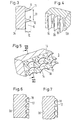
- FIG. 3 shows the geometry of the recesses 6 and the shoulders 8 produced in a processing step I on a shell blank 2c.
- the shoulders 8 have an acute-angled triangular cross section 9 and have a distance 31 between two adjacent tips 11, 12 which corresponds to approximately twice the amount of their height 10.
- the height 10 is chosen between 0.3 and 2 mm.
- a typical value for height 10 is 1 mm.
- the shape of the ribs 16 on a deep-drawing tool 13f is visible from FIG.
- the ribs 16 have the shape of a saddle roof 26, the ridge of which is rounded and are perpendicular to a base surface 36 with their central plane, the central planes running parallel to the direction of insertion and attachment 40.
- These ribs produce, by plastic deformation, the trenches 15 visible in FIG. 5, which divide the shoulders into shoulder sections 14. Since the deep-drawing tool moves against the anchoring surface 3 against the direction of insertion and fastening, the shoulder edges 17 of the shoulder sections 14 are pulled down, so that 40 cup shapes 18 are created against the direction of insertion and fastening.
- 6 and 7 show, on a section of a shell blank 2d, shoulder edges 17 drawn down to different degrees.
- the geometry of the cup shape 18 can be controlled by changing the shoulders 8 and the ribs 16. Furthermore, the smaller the angles ⁇ of the anchoring surface 3 to the direction of insertion and fastening 40, the further the shoulder edges 17 are pulled down. In the case of the outer hip joint shell in FIG. 1, this means that the typical cup shapes 18 are formed there in a pronounced manner, where they are most needed against undressing, namely towards equator 32.
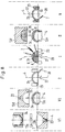
- FIG. 8 shows a work sequence for shaping an outer hip joint shell without taking heat treatments that may be in between into account.
- a rondelle 1 made of titanium sheet is inserted into a deep-drawing mold 13b, fixed with a hold-down device 24 and drawn by a tool punch 13a into a shell, which is ejected in the direction of the polar axis 4 using an ejector 22.
- this shell blank is placed on a support body 13c and optionally receives additional longitudinal grooves 29 with a deep-drawing tool 13d, which is provided with bumps 25 in the longitudinal direction, for later securing against rotation in the bone bed.
- receiving surfaces are turned on in the area of the equator. A direction of rotation 27, an axis of rotation 28, a clamping tool 23 and a turning tool 7 are only indicated symbolically.
- a shell blank 2b is clamped on its receiving surfaces on the equator with a clamping tool 23 and provided with recesses 6 on the anchoring surface.
- the axis of rotation 28 in the direction of the polar axis 4, the direction of rotation 27 and the turning tool 7 are indicated symbolically.
- the geometry of the recesses 6 and the shoulders 8 has already been described previously.
- the turning tool 7 is pivoted here about the ball center 5 of the outer shell.
- shaped steels can also be used on different widths of the spherical shell.
- a shell blank 2c prepared in this way which has shoulders transversely to the insertion and fastening direction 40, is placed on a support body 13e in a deep-drawing tool and in a process step II with a deep-drawing mold 13f, which has a hemispherical shape with ribs 26 protruding in the meridians his shoulders 8 deformed.
- the ribs 26, which strike against the direction of insertion and fastening, produce the trenches 15 shown in FIG. 5 and the shoulder sections 14 with the cup shape 18.
- the shell blank 2d is picked up on its receiving surfaces on the equator with a clamping tool 23, around the inner contour 19 ready to shoot.
- the axis of rotation 28 in the direction of the polar axis 4, the turning tool 7 and the direction of rotation 27 are only indicated symbolically.
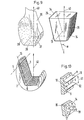
- surfaces 37, 38, 39 have been produced on a femoral stump by resection, on which the anchoring surfaces 3 of an upper part of a knee joint shown as blank 2 are intended to engage in an insertion and fastening direction 40.
- An associated pressing tool 13 has base surfaces 34 which correspond to the resection surfaces 37, 38, 39 and have the ribs 26 which run with their central plane perpendicular to the base surface 34 and parallel to the direction of insertion and attachment 40.
- 2 punctures 6 are made on the blank, the shoulders 8 are left standing.
- the shoulders 8 are shown enlarged with a puncture 6.
- the shoulder height 10 is between 0.3 and 2 mm while the distance 31 between the shoulder tips 11, 12 corresponds approximately to twice the amount of the shoulder height 10.
- the cross section of the shoulders 8 corresponds to an acute-angled triangular cross section 9.
- trenches 15 are formed in the anchoring surfaces 3, which divide the shoulders 8 into shoulder sections 14 as shown in the lower part of FIG. 10 and pull the shoulder edges 17 down against the direction of insertion and fastening 40 and produce cup shapes 18.
Landscapes
- Health & Medical Sciences (AREA)
- Orthopedic Medicine & Surgery (AREA)
- Engineering & Computer Science (AREA)
- Heart & Thoracic Surgery (AREA)
- Life Sciences & Earth Sciences (AREA)
- Oral & Maxillofacial Surgery (AREA)
- Transplantation (AREA)
- Biomedical Technology (AREA)
- Veterinary Medicine (AREA)
- Vascular Medicine (AREA)
- Cardiology (AREA)
- Animal Behavior & Ethology (AREA)
- General Health & Medical Sciences (AREA)
- Public Health (AREA)
- Mechanical Engineering (AREA)
- Prostheses (AREA)
- Curing Cements, Concrete, And Artificial Stone (AREA)
- Joining Of Building Structures In Genera (AREA)
Abstract
Description
- Die Erfindung handelt von einem Verfahren zur Erzeugung von äusseren Verankerungsflächen an Gelenkimplantaten aus einem plastisch verformbaren Metall, wobei die Verankerungsflächen in einem Winkel α zwischen 0 und 90 Grad zu einer Einbring- und Befestigungsrichtung des Gelenkimplantats stehen.
- Gelenkimplantate müssen an ihren Verankerungsflächen zum Knochengewebe in verschiedenen Richtungen Kräfte übernehmen. Die Verankerungsflächen sollten daher in möglichst vielen Richtungen Kräfte übertragen können, ohne dass eine Lockerung vom Implantat einsetzt. Unter diesem Aspekt wurden verschiedene Texturen für Verankerungsflächen entwickelt. So zeigt die EP 0 186 471 eine Kniegelenkprothese mit sägezahnartigen Rillen, die quer zur Einbringrichtung angebracht sind, wobei die Stabilität in der Richtung der Rillen reduziert ist. Eine weitere Alternative sieht an der Prothese widerhakenähnliche Stifte vor, welche in Einbringrichtung in den Femurstumpf eindringen. Eine generelle Anforderung an Verankerungsflächen dieser Art ist, dass sie einmal eine dem Einwachsen förderliche Struktur aufweisen sollten und dass sie andererseits wirtschaftlich herstellbar sein sollten. Die DE 29 14 513 zeigt Verankerungsflächen, die mit warzenähnlichen Vorsprüngen und Vertiefungen versehen sind, um das Einwachsen zu verbessern. Es werden keine Angaben zur Erzeugung und zu den absoluten Dimensionen dieser Struktur gemacht. In den relativen geometrischen Verhältnissen werden allseitig verrundete Formen vorgeschlagen, die nur eine begrenzte Primärverankerung zulassen. Eine weitere Struktur wird in der EP 0 381 351 vorgeschlagen, bei der an einer Hüftgelenkschale an einem gegen aussen vorstehenden Wulst durch schräg zum Äquator verlaufende und in Umfangsrichtung versetzte Einstiche, die sich kreuzen, eine Art randrierte Verankerungsfläche mit abgeplatteten vorstehenden Pyramiden erzeugt wird. Auch hier ist die Primärverankerung begrenzt, d.h. sehr stark von der Vorspannung im Knochenhohlraum respektive vom Untermass des Knochenhohlraums im Bereich des Äquators abhängig.
- Aufgabe der Erfindung ist es Verankerungsflächen zu schaffen, bei denen eine gute Verankerung mit einem kostengünstigen Herstellverfahren erreichbar ist. Diese Aufgabe wird dadurch gelöst, dass in einem Schritt I an einem Rohling in den Verankerungsflächen Einstiche quer zur Einbring- und Befestigungsrichtung durch Spanen, Giessen oder Pressen erzeugt werden, sodass spitzwinklige Schultern stehen bleiben, welche eine Höhe in einem Betrag zwischen 0,3 und 2 mm aufweisen, während der Abstand zweier benachbarter Schulterspitzen annähernd dem Betrag der zweifachen Höhe entspricht, und dass in einem Schritt II der Rohling mit einem Presswerkzeug, dessen Grundfläche der Hüllfläche an den Verankerungsflächen des Rohlings entspricht und aus dessen Grundfläche Rippen vorstehen, welche mit ihren Mittelebenen senkrecht zur Grundfläche und parallel zur Einbring- und Befestigungsrichtung verlaufen, durch Pressen in der Einbring- und Befestigungsrichtung soweit verformt wird, dass mit den Rippen quer zu den Schultern Gräben erzeugt werden, welche Schulterabschnitte stehen lassen, wobei die Schulterränder im Bereich der Gräben entgegen der Einbring- und Befestigungsrichtung plastisch deformiert werden, um auf diese Weise aus den Schulterabschnitten Becherformen zu erzeugen, welche entgegen der Einbring- und Befestigungsrichtung geöffnet sind.
- Die Erfindung hat den Vorteil, dass durch eine für die die plastische Verformung vorbereitete Geometrie an den Verankerungsflächen und eine mit einfachen Mitteln daran anschliessende Verformung komplexe Formen herstellbar sind, die für eine Verankerung im Knochengewebe besonders geeignet sind und die mit anderen Verfahren kaum erreichbar sind. Bezogen auf die Einbring- und Befestigungsrichtung wird eine Vielzahl von Bechern an den Verankerungsflächen, welche in einem Winkel α zwischen 0 und 90 Grad zur Einbring- und Befestigungsrichtung stehen, erzeugt. Der einzelne Becher ist dabei wie der Becher eines Peltonrades entgegen der Einbring- und Befestigungsrichtung geöffnet. Er stützt sich mit der hohlen Innenseite im Knochengewebe entgegen der Einbring- und Befestigungsrichtung ab. Durch die gekrümmte Innenfläche der Becher und durch die mit der Herstellung der Becherform entstandenen Gräben zwischen den Bechern wird ein seitliches Weggleiten der Verankerungsfläche quer zur Einbring- und Befestigungsrichtung verhindert. Dabei sind die absoluten Dimensionen der Becherform so gewählt, dass sich Knochengewebe unter Vorspannung in die Bereiche zwischen den Bechern hineindeformiert, um eine gute Primärverankerung entgegen der Einbring- und Befestigungsrichtung zu erreichen. Ein Vorteil des Verfahrens besteht darin, dass eine endgültige Becherform entsteht, ohne dass für diese eine entsprechende Erzeugende zur Herstellung notwendig ist. Dadurch dass quer zur Einbring- und Befestigungsrichtung in den Verankerungsflächen Einstiche und Schultern erzeugt werden, dass die Abstände der Schultern etwa dem Zweifachen ihrer Höhe entsprechen und dass die Schultern im Querschnitt spitzwinklig sind, lassen sich diese in Querrichtung, d.h. entgegen der Einbring- und Befestigungsrichtung plastisch deformieren, um Becherformen zu erzeugen. Dabei ist es wichtig, dass die Höhe der Schultern zwischen 0,3 und 2 mm beträgt, um eine der Knochenstruktur günstig angepasste Grösse der Verankerungsgeometrie zu erhalten. Die Schultern können durch Spanen, Giessen oder Pressen am Rohling erzeugt werden. In einem weiteren Schritt wird der Rohling mit einem Presswerkzeug, das Rippen quer zu den Schultern aufweist verformt, wobei die Mittelebenen der Rippen senkrecht zur Grundfläche und parallel zur Einbring- und Befestigungsrichtung verlaufen. Bei einem Winkel von 0 < α < 90 Grad der Grundfläche zur Einbring- und Befestigungsrichtung entsteht durch die Rippen ein schleifender Schnitt der die Schultern entgegen der Einbring- und Befestigungsrichtung in Schulterabschnitte auftrennt, und letztere an ihren Rändern zu den so entstandenen Gräben entgegen der Einbring- und Befestigungsrichtung zu Bechern verformt. Die Ränder können dabei bis in die Ebene der nachfolgenden Schulter herabgebogen werden. Die Grösse der Verformung muss dabei der plastischen Verformbarkeit des Grundmaterials angepasst werden. Für Reintitan, das ein gängiger Werkstoff für Verankerungsflächen ist, sind Verformungen im Betrag der Schulterhöhe möglich. Die so in der Feinstruktur entstandenen Gräben lassen beim Einbringen in das Knochenbett Rippen stehen, die das Implantat bis zur Verankerung führen und gleichzeitig eine Verschiebung in der Richtung der Schultern verhindern.
- Im Fall einer femurseitigen Verankerungsfläche an einem Kniegelenkimplantat entspricht das Presswerkzeug dem zur Implantation vorbereiteten Femurstumpf, wobei aus den den Verankerungsflächen entsprechende Flächen die mit ihren Mittelebenen zur Einbring- und Verankerungsrichtung parallelen Rippen herausragen.
- Im Fall einer äusseren Hüftgelenkschale entspricht das Presswerkzeug einem beispielsweise halbkugelförmigen Knochenbett, wobei an den Medianen Rippen vorstehen, deren Anzahl am Umfang mit Annäherung an dem Äquator zunimmt. Die Einbring- und Befestigungsrichtung fällt dann mit der Polachse zusammen. Diese relativ einfache Gestaltung des Presswerkzeugs, das zum Beispiel mittels Funkenerosion herstellbar ist, ermöglicht eine günstige Massenfertigung für die relativ komplexen Becherformen in den Verankerungsflächen eines Implantats.
- Im folgenden ist die Erfindung anhand von Ausführungsbeispielen beschrieben. Es zeigen:
- Fig. 1
- schematisch den Schnitt durch eine äussere Hüftgelenkschale, die eine Verankerungsfläche mit becherförmigen Schulterabschnitten entgegen der Einbring- und Verankerungsrichtung aufweist;
- Fig. 2
- schematisch eine Draufsicht auf die Hüftgelenkschale von Fig. 1, wobei die Schultern und die in Meridianen verlaufenden Gräben durch Striche angedeutet sind;
- Fig. 3
- schematisch einen vergrösserten Schnitt durch die mit Einstichen vorbearbeitete Verankerungsfläche an einem Rohling einer äusseren Hüftgelenkschale;
- Fig. 4
- schematisch den Ausschnitt eines Presswerkzeugs mit Rippen, deren Mittelebenen senkrecht zur Grundfläche und parallel zur Einbring- und Befestigungsrichtung verlaufen;
- Fig. 5
- schematisch den Ausschnitt einer Verankerungsfläche mit becherförmigen Schulterabschnitten;
- Fig. 6 und 7
- schematisch einen Schnitt durch die becherförmigen Verankerungsflächen in Fig. 5, wobei die Ränder der Schultern unterschiedlich weit entgegen der Einbring- und Befestigungsrichtung zur nächsten Schulter heruntergezogen sind;
- Fig. 8
- eine mögliche Arbeitsfolge für die Formgebung an einer äusseren Hüftgelenkschale mit becherförmigen Verankerungsflächen;
- Fig. 9
- schematisch die strukturierte Verankerungsfläche mit Becherform an einer femurseitigen Kniegelenkprothese mit dem vorbearbeiteten Femur und dem diesen entsprechenden Presswerkzeug und
- Fig. 10
- den Ausschnitt eines mit Einstichen und Schultern vorbearbeiteten Rohlings gemäss Fig. 9 und die nach dem Eingriff des Presswerkzeugs verformten Schulterabschnitte.
- Die Figuren zeigen Verfahrensschritte zur Erzeugung von Verankerungsflächen 3 an metallischen Gelenkimplantaten, die in einem Winkel 0 < α < 90 Grad entgegen der Einbring- und Befestigungsrichtung 40 stehen und becherförmige Schulterabschnitte 14 aufweisen, welche zur Verankerung entgegen der Einbring- und Befestigungsrichtung 40 geöffnet sind. In einem ersten Schritt werden durch Spanen, Giessen oder Fressen Einstiche 6 und Schultern 8 in den Verankerungsflächen 3 eines Rohlings 2 quer zur Einbring- und Befestigungsrichtung 40 erzeugt. Die Schultern 8 sind spitzwinklig im Querschnitt, haben eine Höhe 10 zwischen 0,3 und 2 mm und einen Abstand 31 der annähernd dem Betrag der zweifachen Höhe 10 entspricht. In einem zweiten Schritt werden mit einem Presswerkzeug 13, das zu den Verankerungsflächen 3 Gegenflächen aufweist, welche mit vorstehenden Rippen 26 versehen sind, die mit ihren Mittelebenen senkrecht zur Gegenfläche und parallel zur Einbring- und Befestigungsrichtung 40 stehen, Gräben 15 durch die Schultern 8 erzeugt. Dabei verformen sich die Ränder 17 der Schulterabschnitte 14 und es entstehen becherartige entgegen der Einbring- und Befestigungsrichtung 40 geöffnete Formen 18 zur Abstützung.
- In den Figuren 1 und 2 ist eine fertig bearbeitete äussere Hüftgelenkschale gezeigt, die bezüglich ihrer Formgebung nach den in Figur 8 angedeuteten Fertigungsschritten bearbeitet wurde. Sie besitzt eine halbkugelähnliche Innenkontur 19 für die Aufnahme einer hier nicht gezeigten Innenschale, welche mit einer Schnappverbindung am Äquator 32 einrastet. In der Polachse 4 liegt am Pol 33 eine Zentrierbohrung 30 mit Innengewinde für ein Einschlagwerkzeug. Am Äquator bestehen Aufnahmeflächen 20, 21, an denen die Aussenschale zur Bearbeitung der Innenkontur 19 mit einem Spannwerkzeug aufgenommen werden kann. Ueber den Umfang sind sechs Längsrillen 29 verteilt, die der zusätzlichen Drehsicherung bei der Verankerung der Aussenschale dienen. Entsprechend Figur 8 können diese Längsschlitze mit einem Tiefziehwerkzeug 13d in einem Vorschritt V2 aufgebracht werden. Die Struktur der eigentlichen Verankerungsfläche 3 ergibt sich aus Einstichen 6 und vorstehenden Schultern 8, welche quer zur Einbring- und Befestigungsrichtung auf bestimmten Breitengraden angeordnet sind. Durch ein Tiefziehwerkzeug 13f mit in Richtung der Meridiane vorstehenden Rippen sind Gräben 15 eingepresst worden, die von den Schultern 8 nur noch Schulterabschnitte 14 stehenlassen.
- In Figur 3 ist die in einem Bearbeitungsschritt I an einem Schalenrohling 2c erzeugte Geometrie der Einstiche 6 und der Schultern 8 gezeigt. Die Schultern 8 weisen einen spitzwinkligen Dreieckquerschnitt 9 auf und haben zwischen zwei benachbarten Spitzen 11, 12 einen Abstand 31 der etwa dem doppelten Betrag ihrer Höhe 10 entspricht. Um für das Einwachsen und Verankern günstige Verhältnisse zu schaffen, wird die Höhe 10 zwischen 0,3 und 2 mm gewählt. Ein typischer Wert für die Höhe 10 ist 1 mm.
- Aus Figur 4 ist die Form der Rippen 16 an einem Tiefziehwerkzeug 13f sichtbar. Die Rippen 16 haben die Form eines Satteldachs 26, dessen First verrundet ist und stehen mit ihrer Mittelebene senkrecht von einer Grundfläche 36 weg, wobei die Mittelebenen parallel zur Einbring- und Befestigungsrichtung 40 verlaufen. Diese Rippen erzeugen durch plastische Verformung die in Figur 5 sichtbaren Gräben 15, welche die Schultern in Schulterabschnitte 14 aufteilen. Da das Tiefziehwerkzeug entgegen der Einbring- und Befestigungsrichtung auf die Verankerungsfläche 3 auffährt, werden die Schulterränder 17 der Schulterabschnitte 14 herabgezogen, sodass entgegen der Einbring- und Befestigungsrichtung 40 Becherformen 18 entstehen. Figuren 6 und 7 zeigen an einem Ausschnitt eines Schalenrohlings 2d unterschiedlich weit herabgezogene Schulterränder 17. Die Geometrie der Becherform 18 ist mit der Veränderung der Schultern 8 und der Rippen 16 steuerbar. Je kleiner im weiteren die Winkel α der Verankerungsfläche 3 zur Einbring- und Befestigungsrichtung 40 sind, desto weiter werden die Schulterränder 17 herabgezogen. Im Fall der äusseren Hüftgelenkschale in Figur 1 bedeutet dies, dass die typischen Becherformen 18 am ausgeprägten dort entstehen, wo sie am meisten gegen das Ausziehen benötigt werden, nämlich zum Äquator 32 hin.
- In Figur 8 ist eine Arbeitsfolge für die Formgebung an einer äusseren Hüftgelenkschale gezeigt, ohne eventuell dazwischenliegende Wärmebehandlungen zu berücksichtigen.
- In einem Vorschritt V1 wird eine Rondelle 1 aus Titanblech in eine Tiefziehform 13b eingelegt, mit einem Niederhalter 24 fixiert und durch einen Werkzeugstempel 13a zu einer Schale gezogen, die mit einem Ausstosser 22 in Richtung der Polachse 4 ausgeworfen wird. Dieser Schalenrohling wird in einem Vorschritt V2 auf einen Stützkörper 13c aufgelegt und erhält fakultativ mit einem Tiefziehwerkzeug 13d, welches mit Buckeln 25 in Längsrichtung versehen ist, zusätzliche Längsrillen 29 für die spätere Drehsicherung im Knochenbett. In einem Zwischenschritt Z werden Aufnahmeflächen im Bereich des Äquators angedreht. Eine Drehrichtung 27, eine Drehachse 28, ein Spannwerkzeug 23 und ein Drehstahl 7 sind nur symbolisch angedeutet.
- In einem Verfahrensschritt I wird ein Schalenrohling 2b an seinen Aufnahmeflächen am Äquator mit einem Spannwerkzeug 23 eingespannt und auf der Verankerungsfläche mit Einstichen 6 versehen. Die Drehachse 28 in der Richtung der Polachse 4, die Drehrichtung 27 und der Drehstahl 7 sind symbolisch angedeutet. Die Geometrie der Einstiche 6 und der Schultern 8 wurde bereits vorher beschrieben. Der Drehstahl 7 wird hier um den Kugelmittelpunkt 5 der Aussenschale geschwenkt. Es können aber auch Formstähle auf verschiedenen Breiten der Kugelschale eingesetzt werden. Ein so vorbereiteter Schalenrohling 2c, der Schultern quer zur Einbring- und Befestigungsrichtung 40 aufweist wird in einem Tiefziehwerkzeug auf einen Stützkörper 13e aufgesetzt und in einem Verfahrensschritt II mit einer Tiefziehform 13f, welche eine Halbkugelform mit in den Meridianen vorstehenden Rippen 26 aufweist, an seinen Schultern 8 verformt. Die entgegen der Einbring- und Befestigungsrichtung auftreffenden Rippen 26 erzeugen die in Figur 5 gezeigten Gräben 15 und die Schulterabschnitte 14 mit der Becherform 18. In einem Nachfolgeschritt N wird der Schalenrohling 2d an seinen Aufnahmeflächen am Äquator mit einem Spannwerkzeug 23 aufgenommen, um die Innenkontur 19 fertig zu drehen. Die Drehachse 28 in Richtung der Polachse 4, der Drehstahl 7 und die Drehrichtung 27 sind nur symbolisch angedeutet.
- In Figur 9 sind an einem Femurstumpf 35 Flächen 37, 38, 39 durch Resektion erzeugt worden, an denen die Verankerungsflächen 3 eines als Rohling 2 gezeigten Oberteils eines Kniegelenks in einer Einbring- und Befestigungsrichtung 40 eingreifen sollen. Ein zugehöriges Presswerkzeug 13 besitzt Grundflächen 34, die den Resektionsflächen 37, 38, 39 entsprechen und die Rippen 26 aufweisen, welche mit ihrer Mittelebene senkrecht zur Grundfläche 34 und parallel zur Einbring- und Befestigungsrichtung 40 verlaufen. Quer zur Einbring- und Befestigungsrichtung 40 sind am Rohling 2 Einstiche 6 angebracht, die Schultern 8 stehenlassen. Im oberen Teil von Figur 10 sind die Schultern 8 mit einem Einstich 6 vergrössert gezeigt. Die Schulterhöhe 10 beträgt zwischen 0,3 und 2 mm während der Abstand 31 der Schulterspitzen 11, 12 etwa dem zweifachen Betrag der Schulterhöhe 10 entspricht. Der Querschnitt der Schultern 8 entspricht einem spitzwinkligen Dreiecksquerschnitt 9.
- Beim Einfahren des Werkzeugs 13 in den Rohling 2 entstehen in den Verankerungsflächen 3 Gräben 15, welche die Schultern 8 wie im unteren Teil von Figur 10 gezeigt in Schulterabschnitte 14 unterteilen und entgegen der Einbring- und Befestigungsrichtung 40 die Schulterränder 17 herabziehen und Becherformen 18 erzeugen. Je kleiner der Winkel α zwischen Grundfläche 34 und der Einbring- und Befestigungsrichtung 40 ist, desto ausgeprägter sind die Becherformen.
Claims (9)
- Verfahren zur Erzeugung von äusseren Verankerungsflächen (3) an Gelenkimplantaten aus einem plastisch verformbaren Metall, wobei die Verankerungsflächen in einem Winkel α zwischen 0 und 90 Grad zu einer Einbring- und Befestigungsrichtung (40) des Gelenkimplantats stehen, dadurch gekennzeichnet, dass in einem Schritt I an einem Rohling (2) in den Verankerungsflächen Einstiche (6) quer zur Einbring- und Befestigungsrichtung durch Spanen, Giessen oder Fressen erzeugt werden, sodass spitzwinklige Schultern (8) stehen bleiben, welche eine Höhe (10) in einem Betrag zwischen 0,3 und 2 mm aufweisen, während der Abstand zweier benachbarter Schulterspitzen (11, 12) annähernd dem Betrag der zweifachen Höhe (10) entspricht, und dass in einem Schritt II der Rohling (2) mit einem Presswerkzeug (13), dessen Grundfläche (34) der Hüllfläche an den Verankerungsflächen (3) des Rohlings (2) entspricht und aus dessen Grundfläche (34) Rippen (26) vorstehen, welche mit ihren Mittelebenen senkrecht zur Grundfläche (34) und parallel zur Einbring- und Befestigungsrichtung (40) verlaufen, durch Pressen in der Einbring- und Befestigungsrichtung (40) soweit verformt wird, dass mit den Rippen (26) quer zu den Schultern (8) Gräben (15) erzeugt werden, welche Schulterabschnitte (14) stehen lassen, wobei die Schulterränder (17) im Bereich der Gräben (15) entgegen der Einbring- und Befestigungsrichtung (40) plastisch deformiert werden, um auf diese Weise aus den Schulterabschnitten (14) Becherformen (18) zu erzeugen, welche entgegen der Einbring- und Befestigungsrichtung (40) geöffnet sind.
- Gelenkimplantat mit Verankerungsflächen, welche entsprechend dem Verfahren nach Anspruch 1 hergestellt sind.
- Verfahren zur Erzeugung von äusseren Verankerungsflächen (3) an metallischen Hüftgelenkschalen, die vorzugsweise aus Reintitan bestehen, dadurch gekennzeichnet, dass in einem Schritt I an einem Schalenrohling (2b) in Form einer annähernd kugelförmigen Halbschale durch Drehen um deren Polachse (4) Einstiche (6) mit einem Stahl (7) erzeugt werden, die zwischen sich spitzwinklige Schultern stehen lassen, deren Höhe (10) einen Betrag zwischen 0,3 und 2 mm aufweist, während der Abstand (31) zweier Schulterspitzen (11, 12) annähernd dem Betrag der zweifachen Höhe (10) entspricht, und dass in einem Schritt II der Schalenrohling (2c) in einem Tiefziehwerkzeug (13e, 13f) mit halbkugeliger Aussparung, welche in Richtung zur Polachse (4) auf Meridianen vorstehende Rippen (26) aufweist, die so bemessen sind, dass sie beim Pressen des Schalenrohlings in der Richtung der Polachse (4) quer durch die Schultern (8) Gräben (15) mit dazwischenliegenden Schulterabschnitten erzeugen, dass sie mit zunehmender Annäherung von der Polseite an den Äquator (32) der Schale die Schulterränder (17) im Bereich der Gräben (15) zum Äquator hin plastisch deformieren und dass auf diese Weise aus Schulterabschnitten (14) zum Äquator hin geöffnete Becherformen (18) erzeugt werden.
- Verfahren nach Anspruch 3, dadurch gekennzeichnet, dass die Rippen (26) auf den Meridianen des Tiefziehwerkzeuges (13e, 13f) einen Abstand zwischen 0,5 und 4 mm zueinander aufweisen und die Form eines spitzwinkligen Satteldachs (16) aufweisen.
- Verfahren nach Anspruch 3 oder 4, dadurch gekennzeichnet, dass in einem Vorschritt V1 der Schalenrohling (2a) aus einer Blechrondelle (1) in einem Tiefziehwerkzeug (13a, 13b, 24) geformt wird.
- Verfahren nach einem der Ansprüche 3 bis 5, dadurch gekennzeichnet, dass in einem Vorschritt V2 mit einem Tiefziehwerkzeug (13c, 13d, 22) mindestens drei Längsrillen (29) am Umfang des Äquators angebracht werden.
- Verfahren nach einem der Ansprüche 3 bis 6, dadurch gekennzeichnet, dass in einem Zwischenschritt Z Aufnahmeflächen (20, 21) für Spannmittel (23) der späteren Bearbeitungsschritte angebracht werden.
- Verfahren nach einem der Ansprüche 3 bis 6, dadurch gekennzeichnet, dass in einem Nachfolgeschritt N eine Innenkontur (19) der metallischen Hüftgelenkschale zur Aufnahme und Verankerung einer Pfanne fertig bearbeitet wird.
- Metallische Hüftgelenkschale vorzugsweise aus Reintitan, zur Verankerung in einem Beckenknochen, wobei die Schale nach einem Verfahren entsprechend einem der Ansprüche 3 bis 8 bearbeitet ist.
Priority Applications (7)
| Application Number | Priority Date | Filing Date | Title |
|---|---|---|---|
| ES93810583T ES2149194T3 (es) | 1993-08-18 | 1993-08-18 | Procedimiento para formar superficies de anclaje en saliente sobre implantes de articulaciones. |
| AT93810583T ATE194274T1 (de) | 1993-08-18 | 1993-08-18 | Verfahren zur erzeugung von äusseren verankerungsflächen an gelenkimplantaten |
| DE59310070T DE59310070D1 (de) | 1993-08-18 | 1993-08-18 | Verfahren zur Erzeugung von äusseren Verankerungsflächen an Gelenkimplantaten |
| EP93810583A EP0639356B1 (de) | 1993-08-18 | 1993-08-18 | Verfahren zur Erzeugung von äusseren Verankerungsflächen an Gelenkimplantaten |
| JP11910194A JP3529157B2 (ja) | 1993-08-18 | 1994-05-31 | 関節移植組織の外部取付面の製造方法 |
| US08/258,629 US5553476A (en) | 1993-08-18 | 1994-06-10 | Process for the production of outer attachment faces on joint implants |
| US08/684,111 US5755799A (en) | 1993-08-18 | 1996-07-19 | Joint implant with self-engaging attachment surface |
Applications Claiming Priority (1)
| Application Number | Priority Date | Filing Date | Title |
|---|---|---|---|
| EP93810583A EP0639356B1 (de) | 1993-08-18 | 1993-08-18 | Verfahren zur Erzeugung von äusseren Verankerungsflächen an Gelenkimplantaten |
Publications (2)
| Publication Number | Publication Date |
|---|---|
| EP0639356A1 true EP0639356A1 (de) | 1995-02-22 |
| EP0639356B1 EP0639356B1 (de) | 2000-07-05 |
Family
ID=8215014
Family Applications (1)
| Application Number | Title | Priority Date | Filing Date |
|---|---|---|---|
| EP93810583A Expired - Lifetime EP0639356B1 (de) | 1993-08-18 | 1993-08-18 | Verfahren zur Erzeugung von äusseren Verankerungsflächen an Gelenkimplantaten |
Country Status (6)
| Country | Link |
|---|---|
| US (2) | US5553476A (de) |
| EP (1) | EP0639356B1 (de) |
| JP (1) | JP3529157B2 (de) |
| AT (1) | ATE194274T1 (de) |
| DE (1) | DE59310070D1 (de) |
| ES (1) | ES2149194T3 (de) |
Cited By (9)
| Publication number | Priority date | Publication date | Assignee | Title |
|---|---|---|---|---|
| EP0867159A1 (de) * | 1997-03-25 | 1998-09-30 | Sulzer Orthopädie AG | Zweischalige künstliche Hüftgelenkpfanne und deren Herstellung |
| WO1999013700A3 (de) * | 1999-01-12 | 1999-11-25 | Lipat Consulting Ag | Oberflächenstruktur für ein enossales implantat |
| WO2009022911A3 (en) * | 2007-08-16 | 2009-06-11 | Cam Implants Bv | Prosthesis comprising an anti-micromotion bone-interfacing surface and method for the manufacture thereof |
| US7799087B2 (en) | 2005-08-31 | 2010-09-21 | Zimmer Gmbh | Implant |
| EP2338443A1 (de) * | 2009-12-23 | 2011-06-29 | Atesos medical AG | Künstliche Hüftgelenkpfanne zur unzementierten Verankerung |
| WO2012113690A2 (de) | 2011-02-22 | 2012-08-30 | Jossi Holding Ag | Verfahren zur herstellung eines implantats mit mindestens einem bereich mit einer oberflächenstruktur, nach dem verfahren hergestelltes implantat und vorrichtung zur durchführung des verfahrens |
| US8308807B2 (en) | 2005-11-09 | 2012-11-13 | Zimmer, Gmbh | Implant with differential anchoring |
| US8632601B2 (en) | 2006-04-28 | 2014-01-21 | Zimmer, Gmbh | Implant |
| US8979935B2 (en) | 2007-07-31 | 2015-03-17 | Zimmer, Inc. | Joint space interpositional prosthetic device with internal bearing surfaces |
Families Citing this family (46)
| Publication number | Priority date | Publication date | Assignee | Title |
|---|---|---|---|---|
| ES2180015T3 (es) * | 1996-04-10 | 2003-02-01 | Sulzer Orthopaedie Ag | Implante metalico que comprende una superficie y procedimiento para fabricar la superficie. |
| CA2252510C (en) * | 1996-04-22 | 2005-06-21 | Gerd Hormansdorfer | Hip joint socket with a special thread |
| EP0839016B1 (de) * | 1996-05-14 | 2002-12-04 | Bruno Balay | Zementfrei verankertes hüftgelenkpfannenimplantat |
| US7255712B1 (en) | 1997-04-15 | 2007-08-14 | Active Implants Corporation | Bone growth promoting implant |
| EP0899053A3 (de) * | 1997-08-29 | 2000-04-05 | Sintokogio Ltd. | Plattiertes Produkt und Verfahren und Vorrichtung zu dessen Herstellung |
| US5927136A (en) * | 1997-11-06 | 1999-07-27 | Reynolds; David L. | Method of treating a tubular member |
| US6139582A (en) * | 1997-11-21 | 2000-10-31 | Depuy Orthopaedics, Inc. | Acetabular cup with bi-directional steps |
| DE19757799A1 (de) | 1997-12-29 | 1999-07-01 | Gerd Hoermansdoerfer | Verfahren zum Humpeldrehen und bevorzugte Anwendung des Verfahrens |
| US7115143B1 (en) | 1999-12-08 | 2006-10-03 | Sdgi Holdings, Inc. | Orthopedic implant surface configuration |
| US6827740B1 (en) | 1999-12-08 | 2004-12-07 | Gary K. Michelson | Spinal implant surface configuration |
| JP4452008B2 (ja) * | 2000-12-08 | 2010-04-21 | 住友金属工業株式会社 | 湾曲金属板の製造方法、及びゴルフクラブヘッド |
| US6599322B1 (en) * | 2001-01-25 | 2003-07-29 | Tecomet, Inc. | Method for producing undercut micro recesses in a surface, a surgical implant made thereby, and method for fixing an implant to bone |
| US7018418B2 (en) | 2001-01-25 | 2006-03-28 | Tecomet, Inc. | Textured surface having undercut micro recesses in a surface |
| DE10106863C2 (de) * | 2001-02-14 | 2003-04-03 | Hans Ulrich Staeubli | Implantierbare Pfanne für Hüftgelenk-Endoprothesen |
| ATE295706T1 (de) | 2001-07-31 | 2005-06-15 | Xaver Kuoni | Künstliche gelenkpfanne |
| WO2003047470A2 (en) | 2001-12-04 | 2003-06-12 | Discure Ltd. | Cushion bearing implants for load bearing applications |
| DE60327626D1 (de) * | 2002-05-23 | 2009-06-25 | Active Implants Corp | Gelenk- und zahnimplantate |
| US20040243134A1 (en) * | 2003-05-30 | 2004-12-02 | Walker Peter Stanley | Bone shaping device for knee replacement |
| EP1498090A1 (de) * | 2003-07-16 | 2005-01-19 | WALDEMAR LINK GmbH & Co. KG | Hüftprothese mit einem in den Oberschenkelknochen einzusetzenden Schaft |
| US7080539B2 (en) * | 2003-12-22 | 2006-07-25 | Federal-Mogul World Wide, Inc. | Forged knurled socket housing and method of manufacture |
| US8140489B2 (en) * | 2004-03-24 | 2012-03-20 | Oracle International Corporation | System and method for analyzing content on a web page using an embedded filter |
| US20090048679A1 (en) * | 2006-02-09 | 2009-02-19 | Zimmer Gmbh | Implant |
| FR2915089B1 (fr) * | 2007-04-18 | 2011-10-21 | Cadorel Catherine | Dispositif et procede de creation d'une plaque d'osteo-integration a la surface d'un implant endo-osseux |
| FR2915088B1 (fr) * | 2007-04-18 | 2010-03-12 | Cadorel Catherine | Implant endo-osseux composite a accrochage mecanique optimise et procede de fabrication d'un tel implant. |
| US7780740B2 (en) * | 2007-05-21 | 2010-08-24 | Active Implants Corporation | Methods, systems, and apparatus for implanting prosthetic devices into cartilage |
| DE202007008430U1 (de) * | 2007-06-15 | 2008-10-16 | Heise, Sebastian | Beleuchtungsvorrichtung |
| US9539097B2 (en) | 2007-11-08 | 2017-01-10 | Linares Medical Devices, Llc | Hip and knee joint assemblies incorporating debris collection architecture between the ball and seat interface |
| US8979938B2 (en) * | 2007-11-08 | 2015-03-17 | Linares Medical Devices, Llc | Artificial knee implant including liquid ballast supporting / rotating surfaces and incorporating flexible multi-material and natural lubricant retaining matrix applied to a joint surface |
| US8828088B2 (en) * | 2007-11-08 | 2014-09-09 | Linares Medical Devices, Llc | Joint assembly incorporating undercut surface design to entrap accumulating wear debris from plastic joint assembly |
| US8702801B2 (en) * | 2008-02-25 | 2014-04-22 | Linares Medical Devices, Llc | Artificial wear resistant plug for mounting to existing joint bone |
| WO2009120776A2 (en) * | 2008-03-26 | 2009-10-01 | Linares Medical Devices, Llc | Joint construction, such as for use by athletes |
| US8123815B2 (en) | 2008-11-24 | 2012-02-28 | Biomet Manufacturing Corp. | Multiple bearing acetabular prosthesis |
| US8308810B2 (en) | 2009-07-14 | 2012-11-13 | Biomet Manufacturing Corp. | Multiple bearing acetabular prosthesis |
| US8506569B2 (en) | 2009-12-31 | 2013-08-13 | DePuy Synthes Products, LLC | Reciprocating rasps for use in an orthopaedic surgical procedure |
| US8556901B2 (en) * | 2009-12-31 | 2013-10-15 | DePuy Synthes Products, LLC | Reciprocating rasps for use in an orthopaedic surgical procedure |
| US8926705B2 (en) | 2010-05-10 | 2015-01-06 | Linares Medical Devices, Llc | Implantable joint assembly featuring debris entrapment chamber subassemblies along with opposing magnetic fields generated between articulating implant components in order to minimize frictional force and associated wear |
| US8486076B2 (en) | 2011-01-28 | 2013-07-16 | DePuy Synthes Products, LLC | Oscillating rasp for use in an orthopaedic surgical procedure |
| US9023112B2 (en) * | 2011-02-24 | 2015-05-05 | Depuy (Ireland) | Maintaining proper mechanics THA |
| EP2502604B1 (de) * | 2011-03-21 | 2013-09-25 | Jossi Holding AG | Gelenkpfannenimplantat |
| US9668745B2 (en) | 2011-12-19 | 2017-06-06 | Depuy Ireland Unlimited Company | Anatomical concentric spheres THA |
| US8858645B2 (en) | 2012-06-21 | 2014-10-14 | DePuy Synthes Products, LLC | Constrained mobile bearing hip assembly |
| US9427322B1 (en) * | 2012-06-27 | 2016-08-30 | Signal Medical Corporation | Hip implant |
| GB2547907A (en) * | 2016-03-02 | 2017-09-06 | Invibio Knees Ltd | Prosthesis |
| GB2547908A (en) * | 2016-03-02 | 2017-09-06 | Invibio Knees Ltd | Replacement knee component |
| WO2021217207A1 (en) * | 2020-04-30 | 2021-11-04 | Australian Institute of Robotic Orthopaedics Pty Ltd | An orthopaedic implant and a surgical orthopaedic system incorporating same |
| US12048442B2 (en) * | 2022-01-06 | 2024-07-30 | DePuy Synthes Products, Inc. | Femoral finishing rasp |
Citations (4)
| Publication number | Priority date | Publication date | Assignee | Title |
|---|---|---|---|---|
| EP0108729A1 (de) * | 1982-11-04 | 1984-05-16 | Alberto Scoti | Verfahren zur Herstellung von vergrösserten Wärmetauscherflächen und dazugehöriges Werkzeug |
| EP0169978A1 (de) * | 1984-07-16 | 1986-02-05 | GebràDer Sulzer Aktiengesellschaft | Aus einem inneren Pfannenkörper und einer Aussenschale bestehende Endoprothese für eine Hüftgelenkspfanne |
| EP0186471A2 (de) * | 1984-12-20 | 1986-07-02 | Chas F Thackray Limited | Knieprothese |
| US4865603A (en) * | 1988-02-04 | 1989-09-12 | Joint Medical Products Corporation | Metallic prosthetic devices having micro-textured outer surfaces |
Family Cites Families (16)
| Publication number | Priority date | Publication date | Assignee | Title |
|---|---|---|---|---|
| US3487670A (en) * | 1965-03-29 | 1970-01-06 | Trane Co | Method of forming indentations in fins extending from a heat transfer surface |
| DE2320747A1 (de) * | 1973-04-25 | 1974-11-21 | Muelheimer Gitterrostfabrik Gm | Verfahren zur herstellung von gitterrosten |
| FR2272637B2 (de) * | 1974-05-29 | 1977-09-30 | Ceraver | |
| US4194384A (en) * | 1975-01-13 | 1980-03-25 | Hitachi, Ltd. | Method of manufacturing heat-transfer wall for vapor condensation |
| CH630251A5 (de) * | 1978-05-19 | 1982-06-15 | Sulzer Ag | Oberflaechenstruktur an verankerungselement eines knochenimplantates. |
| CH649913A5 (en) * | 1981-03-19 | 1985-06-28 | Sulzer Ag | Cementlessly anchorable joint socket |
| GB2127327B (en) * | 1982-08-20 | 1986-04-30 | Alton Systems Limited | An antiskid surface treatment for use on scaffolding components |
| US4662891A (en) * | 1983-11-21 | 1987-05-05 | Joint Medical Products Corporation | Fixation elements for artificial joints |
| DE8431422U1 (de) * | 1984-10-23 | 1985-11-21 | Mecron Medizinische Produkte Gmbh, 1000 Berlin | Trägerelement |
| CA1290099C (en) * | 1986-01-21 | 1991-10-08 | Thomas H. Mallory | Porous-coated artificial joints |
| FR2595562B1 (fr) * | 1986-03-13 | 1992-08-28 | Rhenter Jean Luc | Cupule de prothese |
| FR2620932A1 (fr) * | 1987-09-28 | 1989-03-31 | Saffar Philippe | Prothese d'articulation metacarpo-phalangienne ou interphalangienne de doigts |
| CH674708A5 (de) * | 1988-04-11 | 1990-07-13 | Sulzer Ag | |
| US5108446A (en) * | 1990-11-26 | 1992-04-28 | Sulzer Brothers Limited | Hip joint prosthesis |
| JPH0549656A (ja) * | 1991-06-24 | 1993-03-02 | Sumitomo Metal Ind Ltd | 耐摩耗性に優れたチタン合金製人工関節 |
| US5358532A (en) * | 1992-06-16 | 1994-10-25 | Smith & Nephew Richards Inc. | Cementless acetabular cup |
-
1993
- 1993-08-18 ES ES93810583T patent/ES2149194T3/es not_active Expired - Lifetime
- 1993-08-18 AT AT93810583T patent/ATE194274T1/de not_active IP Right Cessation
- 1993-08-18 EP EP93810583A patent/EP0639356B1/de not_active Expired - Lifetime
- 1993-08-18 DE DE59310070T patent/DE59310070D1/de not_active Expired - Lifetime
-
1994
- 1994-05-31 JP JP11910194A patent/JP3529157B2/ja not_active Expired - Fee Related
- 1994-06-10 US US08/258,629 patent/US5553476A/en not_active Expired - Lifetime
-
1996
- 1996-07-19 US US08/684,111 patent/US5755799A/en not_active Expired - Lifetime
Patent Citations (4)
| Publication number | Priority date | Publication date | Assignee | Title |
|---|---|---|---|---|
| EP0108729A1 (de) * | 1982-11-04 | 1984-05-16 | Alberto Scoti | Verfahren zur Herstellung von vergrösserten Wärmetauscherflächen und dazugehöriges Werkzeug |
| EP0169978A1 (de) * | 1984-07-16 | 1986-02-05 | GebràDer Sulzer Aktiengesellschaft | Aus einem inneren Pfannenkörper und einer Aussenschale bestehende Endoprothese für eine Hüftgelenkspfanne |
| EP0186471A2 (de) * | 1984-12-20 | 1986-07-02 | Chas F Thackray Limited | Knieprothese |
| US4865603A (en) * | 1988-02-04 | 1989-09-12 | Joint Medical Products Corporation | Metallic prosthetic devices having micro-textured outer surfaces |
Cited By (13)
| Publication number | Priority date | Publication date | Assignee | Title |
|---|---|---|---|---|
| EP0867159A1 (de) * | 1997-03-25 | 1998-09-30 | Sulzer Orthopädie AG | Zweischalige künstliche Hüftgelenkpfanne und deren Herstellung |
| WO1999013700A3 (de) * | 1999-01-12 | 1999-11-25 | Lipat Consulting Ag | Oberflächenstruktur für ein enossales implantat |
| US6554867B1 (en) | 1999-01-12 | 2003-04-29 | Lipat Consulting Ag | Surface structure for intraosseous implant |
| US7799087B2 (en) | 2005-08-31 | 2010-09-21 | Zimmer Gmbh | Implant |
| US8394149B2 (en) | 2005-08-31 | 2013-03-12 | Zimmer, Gmbh | Method for implantation of a femoral implant |
| US8308807B2 (en) | 2005-11-09 | 2012-11-13 | Zimmer, Gmbh | Implant with differential anchoring |
| US8632601B2 (en) | 2006-04-28 | 2014-01-21 | Zimmer, Gmbh | Implant |
| US8979935B2 (en) | 2007-07-31 | 2015-03-17 | Zimmer, Inc. | Joint space interpositional prosthetic device with internal bearing surfaces |
| WO2009022911A3 (en) * | 2007-08-16 | 2009-06-11 | Cam Implants Bv | Prosthesis comprising an anti-micromotion bone-interfacing surface and method for the manufacture thereof |
| EP2338443A1 (de) * | 2009-12-23 | 2011-06-29 | Atesos medical AG | Künstliche Hüftgelenkpfanne zur unzementierten Verankerung |
| WO2012113690A3 (de) * | 2011-02-22 | 2012-10-26 | Jossi Holding Ag | Verfahren zur herstellung eines implantats mit mindestens einem bereich mit einer oberflächenstruktur, nach dem verfahren hergestelltes implantat und vorrichtung zur durchführung des verfahrens |
| CH704518A1 (de) * | 2011-02-22 | 2012-08-31 | Jossi Holding Ag | Verfahren zur Herstellung eines Implantats mit mindestens einem Bereich mit einer Oberflächenstruktur, nach dem Verfahren hergestelltes Implantat und Vorrichtung zur Durchführung des Verfahrens. |
| WO2012113690A2 (de) | 2011-02-22 | 2012-08-30 | Jossi Holding Ag | Verfahren zur herstellung eines implantats mit mindestens einem bereich mit einer oberflächenstruktur, nach dem verfahren hergestelltes implantat und vorrichtung zur durchführung des verfahrens |
Also Published As
| Publication number | Publication date |
|---|---|
| DE59310070D1 (de) | 2000-08-10 |
| JPH0759803A (ja) | 1995-03-07 |
| JP3529157B2 (ja) | 2004-05-24 |
| ES2149194T3 (es) | 2000-11-01 |
| EP0639356B1 (de) | 2000-07-05 |
| ATE194274T1 (de) | 2000-07-15 |
| US5553476A (en) | 1996-09-10 |
| US5755799A (en) | 1998-05-26 |
Similar Documents
| Publication | Publication Date | Title |
|---|---|---|
| EP0639356B1 (de) | Verfahren zur Erzeugung von äusseren Verankerungsflächen an Gelenkimplantaten | |
| DE3781163T2 (de) | Manschette zum befestigen kuenstlicher gelenke an knochen. | |
| EP0656199B1 (de) | Sphärische Hüftgelenkpfanne | |
| EP0289922B1 (de) | Gelenkprothese und Verfahren zu ihrer Herstellung | |
| EP0699425B1 (de) | Künstliche Hüftgelenkpfanne sowie Verfahren zur Herstellung | |
| EP0169978B1 (de) | Aus einem inneren Pfannenkörper und einer Aussenschale bestehende Endoprothese für eine Hüftgelenkspfanne | |
| EP0159510B1 (de) | Hüftgelenkendoprothese | |
| EP0182176B1 (de) | Verfahren zum Herstellen von Endoprothesen | |
| EP0489684B1 (de) | Implantat zum Aufbau von Knochengewebe | |
| DE3310486C2 (de) | Endoprothesenschaft zum zementfreien Einsetzen in einen Knochenhohlraum | |
| EP1924208B1 (de) | Femur Implantat | |
| DE69529159T2 (de) | Hüftgelenkprothese | |
| EP0867159A1 (de) | Zweischalige künstliche Hüftgelenkpfanne und deren Herstellung | |
| EP0142759A2 (de) | Hüftgelenkpfanne | |
| EP3416594B1 (de) | Implantat zur rekonstruktion einer hüftgelenkpfanne und zumindest eines teils einer beckenstruktur | |
| EP0522999B1 (de) | Patella-Prothese | |
| EP3714840B1 (de) | Hüftpfanne einer hüftgelenk-endoprothese | |
| EP0726066A2 (de) | Implantierbare Gelenkschale | |
| EP0303006A1 (de) | Gelenkpfanne für eine Hüftgelenkendoprothese | |
| EP0663193A1 (de) | Künstliche Hüftgelenkpfanne | |
| DE3822154C2 (de) | Prothetisches Implantat mit einem porösen Kissen und Verfahren zu dessen Herstellung | |
| EP0368796B1 (de) | Verfahren zur Herstellung einer Schaftprothese | |
| DE2454635A1 (de) | Kuenstliches hueftgelenk | |
| DE69514110T2 (de) | Endoprothese | |
| EP1326551A1 (de) | Implantat mit rillenstrucktur |
Legal Events
| Date | Code | Title | Description |
|---|---|---|---|
| PUAI | Public reference made under article 153(3) epc to a published international application that has entered the european phase |
Free format text: ORIGINAL CODE: 0009012 |
|
| AK | Designated contracting states |
Kind code of ref document: A1 Designated state(s): AT BE CH DE ES FR GB IT LI NL SE |
|
| 17P | Request for examination filed |
Effective date: 19950705 |
|
| 17Q | First examination report despatched |
Effective date: 19981210 |
|
| GRAG | Despatch of communication of intention to grant |
Free format text: ORIGINAL CODE: EPIDOS AGRA |
|
| RAP1 | Party data changed (applicant data changed or rights of an application transferred) |
Owner name: SULZER ORTHOPAEDIE AG |
|
| GRAG | Despatch of communication of intention to grant |
Free format text: ORIGINAL CODE: EPIDOS AGRA |
|
| GRAH | Despatch of communication of intention to grant a patent |
Free format text: ORIGINAL CODE: EPIDOS IGRA |
|
| GRAH | Despatch of communication of intention to grant a patent |
Free format text: ORIGINAL CODE: EPIDOS IGRA |
|
| GRAA | (expected) grant |
Free format text: ORIGINAL CODE: 0009210 |
|
| AK | Designated contracting states |
Kind code of ref document: B1 Designated state(s): AT BE CH DE ES FR GB IT LI NL SE |
|
| REF | Corresponds to: |
Ref document number: 194274 Country of ref document: AT Date of ref document: 20000715 Kind code of ref document: T |
|
| REG | Reference to a national code |
Ref country code: CH Ref legal event code: NV Representative=s name: SULZER MANAGEMENT AG Ref country code: CH Ref legal event code: EP |
|
| GBT | Gb: translation of ep patent filed (gb section 77(6)(a)/1977) |
Effective date: 20000705 |
|
| REF | Corresponds to: |
Ref document number: 59310070 Country of ref document: DE Date of ref document: 20000810 |
|
| ITF | It: translation for a ep patent filed | ||
| ET | Fr: translation filed | ||
| REG | Reference to a national code |
Ref country code: ES Ref legal event code: FG2A Ref document number: 2149194 Country of ref document: ES Kind code of ref document: T3 |
|
| PLBE | No opposition filed within time limit |
Free format text: ORIGINAL CODE: 0009261 |
|
| STAA | Information on the status of an ep patent application or granted ep patent |
Free format text: STATUS: NO OPPOSITION FILED WITHIN TIME LIMIT |
|
| 26N | No opposition filed | ||
| REG | Reference to a national code |
Ref country code: GB Ref legal event code: IF02 |
|
| REG | Reference to a national code |
Ref country code: CH Ref legal event code: PUE Owner name: ZIMMER GMBH Free format text: SULZER ORTHOPAEDIE AG#GRABENSTRASSE 25#6340 BAAR (CH) -TRANSFER TO- ZIMMER GMBH#SULZER ALLEE 8#8404 WINTERTHUR (CH) |
|
| NLS | Nl: assignments of ep-patents |
Owner name: ZIMMER GMBH Effective date: 20061010 |
|
| NLT1 | Nl: modifications of names registered in virtue of documents presented to the patent office pursuant to art. 16 a, paragraph 1 |
Owner name: CENTERPULSE ORTHOPEDICS LTD. |
|
| REG | Reference to a national code |
Ref country code: FR Ref legal event code: TP Ref country code: FR Ref legal event code: CD Ref country code: FR Ref legal event code: CA |
|
| BECA | Be: change of holder's address |
Owner name: *ZIMMER G.M.B.H.SULZER ALLEE 8, CH-8404 WINTERTHUR Effective date: 20060802 |
|
| BECH | Be: change of holder |
Owner name: *ZIMMER G.M.B.H. Effective date: 20060802 |
|
| BECN | Be: change of holder's name |
Owner name: *ZIMMER G.M.B.H.SULZER ALLEE 8, CH-8404 WINTERTHUR Effective date: 20060802 Owner name: *ZIMMER G.M.B.H. Effective date: 20060802 |
|
| PGFP | Annual fee paid to national office [announced via postgrant information from national office to epo] |
Ref country code: NL Payment date: 20080813 Year of fee payment: 16 |
|
| PGFP | Annual fee paid to national office [announced via postgrant information from national office to epo] |
Ref country code: AT Payment date: 20080814 Year of fee payment: 16 |
|
| REG | Reference to a national code |
Ref country code: GB Ref legal event code: 732E Free format text: REGISTERED BETWEEN 20100121 AND 20100127 |
|
| REG | Reference to a national code |
Ref country code: NL Ref legal event code: V1 Effective date: 20100301 |
|
| PG25 | Lapsed in a contracting state [announced via postgrant information from national office to epo] |
Ref country code: AT Free format text: LAPSE BECAUSE OF NON-PAYMENT OF DUE FEES Effective date: 20090818 |
|
| PG25 | Lapsed in a contracting state [announced via postgrant information from national office to epo] |
Ref country code: NL Free format text: LAPSE BECAUSE OF NON-PAYMENT OF DUE FEES Effective date: 20100301 |
|
| PGFP | Annual fee paid to national office [announced via postgrant information from national office to epo] |
Ref country code: CH Payment date: 20110824 Year of fee payment: 19 |
|
| PGFP | Annual fee paid to national office [announced via postgrant information from national office to epo] |
Ref country code: SE Payment date: 20110824 Year of fee payment: 19 Ref country code: ES Payment date: 20110825 Year of fee payment: 19 |
|
| PGFP | Annual fee paid to national office [announced via postgrant information from national office to epo] |
Ref country code: GB Payment date: 20120821 Year of fee payment: 20 |
|
| PGFP | Annual fee paid to national office [announced via postgrant information from national office to epo] |
Ref country code: BE Payment date: 20120824 Year of fee payment: 20 Ref country code: DE Payment date: 20120822 Year of fee payment: 20 Ref country code: IT Payment date: 20120822 Year of fee payment: 20 Ref country code: FR Payment date: 20120906 Year of fee payment: 20 |
|
| REG | Reference to a national code |
Ref country code: SE Ref legal event code: EUG |
|
| PG25 | Lapsed in a contracting state [announced via postgrant information from national office to epo] |
Ref country code: SE Free format text: LAPSE BECAUSE OF NON-PAYMENT OF DUE FEES Effective date: 20120819 |
|
| REG | Reference to a national code |
Ref country code: DE Ref legal event code: R071 Ref document number: 59310070 Country of ref document: DE |
|
| REG | Reference to a national code |
Ref country code: CH Ref legal event code: PL |
|
| BE20 | Be: patent expired |
Owner name: *ZIMMER G.M.B.H. Effective date: 20130818 |
|
| REG | Reference to a national code |
Ref country code: GB Ref legal event code: PE20 Expiry date: 20130817 |
|
| REG | Reference to a national code |
Ref country code: ES Ref legal event code: FD2A Effective date: 20131018 |
|
| PG25 | Lapsed in a contracting state [announced via postgrant information from national office to epo] |
Ref country code: DE Free format text: LAPSE BECAUSE OF EXPIRATION OF PROTECTION Effective date: 20130820 Ref country code: ES Free format text: LAPSE BECAUSE OF NON-PAYMENT OF DUE FEES Effective date: 20120819 |
|
| PG25 | Lapsed in a contracting state [announced via postgrant information from national office to epo] |
Ref country code: GB Free format text: LAPSE BECAUSE OF EXPIRATION OF PROTECTION Effective date: 20130817 |