EP0638209B1 - Cable grounding lead-through - Google Patents
Cable grounding lead-through Download PDFInfo
- Publication number
- EP0638209B1 EP0638209B1 EP93908968A EP93908968A EP0638209B1 EP 0638209 B1 EP0638209 B1 EP 0638209B1 EP 93908968 A EP93908968 A EP 93908968A EP 93908968 A EP93908968 A EP 93908968A EP 0638209 B1 EP0638209 B1 EP 0638209B1
- Authority
- EP
- European Patent Office
- Prior art keywords
- support
- plates
- plate
- gaskets
- cables
- Prior art date
- Legal status (The legal status is an assumption and is not a legal conclusion. Google has not performed a legal analysis and makes no representation as to the accuracy of the status listed.)
- Expired - Lifetime
Links
- 239000000463 material Substances 0.000 claims description 3
- 239000002184 metal Substances 0.000 claims description 3
- 230000000712 assembly Effects 0.000 description 1
- 238000000429 assembly Methods 0.000 description 1
- 210000001520 comb Anatomy 0.000 description 1
- 238000010276 construction Methods 0.000 description 1
- 239000003292 glue Substances 0.000 description 1
- 230000037431 insertion Effects 0.000 description 1
- 238000003780 insertion Methods 0.000 description 1
- 230000035515 penetration Effects 0.000 description 1
Images
Classifications
-
- H—ELECTRICITY
- H02—GENERATION; CONVERSION OR DISTRIBUTION OF ELECTRIC POWER
- H02G—INSTALLATION OF ELECTRIC CABLES OR LINES, OR OF COMBINED OPTICAL AND ELECTRIC CABLES OR LINES
- H02G3/00—Installations of electric cables or lines or protective tubing therefor in or on buildings, equivalent structures or vehicles
- H02G3/22—Installations of cables or lines through walls, floors or ceilings, e.g. into buildings
Definitions
- the invention relates to a cable grounding lead-through comprising a conductive support and means attached to it for leading through and grounding cables, said means comprising at least two conductive plates and a conductive gasket disposed on both sides of each plate, the plates being arranged adjacently to one another in such a manner that the gaskets of each adjacent plate are in close contact with each other.
- grounding lead-throughs are used in EMC-shielded devices, in which case cables are grounded through the support to the ground potential of the device, for example to the frame of the device.
- a grounding lead-through comprising superimposed earth plates with EMC gaskets is previously known, e.g. from US-A-3830954 on which the preamble to claim 1 is based.
- cables are stripped at the gaskets and inserted between the gaskets of the superimposed plates, the gaskets being in contact with each other.
- the cabling is effected in layers from below upwards, and the superimposed plates are secured from both edges in the direction of the cables to the vertical side walls of the metal support by means of screws. Finally the structure obtained in this way is closed by a separate cover.
- the most serious drawback of the known grounding lead-through described above is that it is very difficult to do any changes to it. If the grounding must be changed, for example by grounding an additional cable, almost the whole construction must first be disassembled, i.e. the cover must be removed, the fixing screws of the plates must be opened, and a necessary number of plates with cables between them must be detached, and finally the same operations must be carried out in reverse order.
- the known lead-through is also disadvantageous itself owing to its complicated structure.
- the primary object of the present invention is to remove the drawbacks of the known structure described above. This is achieved with a grounding lead-through of the invention, which is characterized in that the support is formed as a rail and the plates are secured substantially perpendicularly from only one edge to the support, whereby the cables to be led through and grounded can be inserted between adjacent gaskets from the side opposite to the support.
- the invention is based on the idea of securing the plates merely from one edge adjacently to a rail-like support formed in an appropriate manner, whereby the cables can simply be inserted between adjacent gaskets that are in contact with each other from the "free" edges of the plates - and the grounding lead-through is finished.
- the insertion of cables between the gaskets can be effected very easily and rapidly, particularly when the gasket is formed from a piece which is cut from a flexible ribbon-like material and bent on both sides of the plate around the edge of the plate opposite to the support.
- the ends of the plates that are opposite to the support should preferably be combined with each other by at least one transverse guiding comb to prevent possible straggling of the plates.
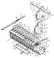
- the grounding lead-through illustrated in the drawing comprises a conductive support 1, conductive plates 2 secured to it, and conductive gaskets disposed on both sides of said plates.
- the cables 4 to be grounded and led through are intended to be inserted between adjacent gaskets 3.
- the support 1 is formed of a profiled metal rail, to which the plates 2 are secured perpendicularly and at such lateral distance from each other that the gaskets of each adjacent plate 2 are in close contact with each other.
- the fixing is effected by means of openings 5 and gaps 6 provided in the rail 1, and one edge of the plate 2 and the brackets 7 provided in it.
- the fixing of the plates 2 is thus effected by inserting them into the rail 1 from the side and vertically with respect to it so that the brackets 7 penetrate into the openings 5, and part of the edge of each plate 2 penetrates into the gaps 6.
- the brackets 7 are turned 30° to 45° upon penetration into the openings 5.
- the gaskets 3 which are attached around the plates 2 before the plates are secured to the rail 1 are formed from pieces which are cut from a flexible ribbon-like material and bent on both sides of the plate 2 around the edge of the plate 2 opposite to the rail 1.
- the width and thickness of the plate 2 are not significant.
- the gasket 3 and the plate 2 may be, for instance, of the same width.
- the plate 2 may also be thicker than the gasket 3 in order for wider spacing to be achieved, for example.
- the gaskets 3 are preferably fixed to the plates 2 by means of narrow sticker strips 8 attached to the gaskets 3. Stickers attached merely to the ends of the gaskets or a dotted line of glue are also conceivable.
- the cables 4 can be grounded and led through simply by inserting the cables 4 between adjacent gaskets 3 from the side opposite to the rail 1, i.e. from above in the drawing, and the grounding lead-through is substantially finished. Before the cables 4 are inserted between the gaskets, they are stripped at the grounding part substantially for the width of the gasket 3, whereby the stripped part 4a of a cable 4 is grounded between adjacent gaskets 3.
- Several cables 4 can be grounded in the same gap, and their width may vary considerably, as the grounding is ensured by the flexibility of the gaskets 3.
- the ends of the plates 2 that are opposite to the rail 1 should preferably be combined by transverse guiding combs 9 which prevent straggling of the plates 2.
- a finished grounding lead-through assembly is secured from the rail 1 to the frame of an EMC-shielded device (not shown), for example.
- the cover of this device can be arranged to be in close contact with the gaskets 3 to form a tight assembly.
Landscapes
- Engineering & Computer Science (AREA)
- Architecture (AREA)
- Civil Engineering (AREA)
- Structural Engineering (AREA)
- Cable Accessories (AREA)
- Shielding Devices Or Components To Electric Or Magnetic Fields (AREA)
- Installation Of Indoor Wiring (AREA)
- Gas Or Oil Filled Cable Accessories (AREA)
Applications Claiming Priority (3)
| Application Number | Priority Date | Filing Date | Title |
|---|---|---|---|
| FI921878 | 1992-04-27 | ||
| FI921878A FI89843C (fi) | 1992-04-27 | 1992-04-27 | Jordningsgenomfoering foer kablar |
| PCT/FI1993/000161 WO1993022815A1 (en) | 1992-04-27 | 1993-04-19 | Cable grounding lead-through |
Publications (2)
| Publication Number | Publication Date |
|---|---|
| EP0638209A1 EP0638209A1 (en) | 1995-02-15 |
| EP0638209B1 true EP0638209B1 (en) | 1996-09-04 |
Family
ID=8535183
Family Applications (1)
| Application Number | Title | Priority Date | Filing Date |
|---|---|---|---|
| EP93908968A Expired - Lifetime EP0638209B1 (en) | 1992-04-27 | 1993-04-19 | Cable grounding lead-through |
Country Status (7)
| Country | Link |
|---|---|
| EP (1) | EP0638209B1 (da) |
| AU (1) | AU667901B2 (da) |
| DE (1) | DE69304527T2 (da) |
| DK (1) | DK0638209T3 (da) |
| FI (1) | FI89843C (da) |
| HK (1) | HK1006611A1 (da) |
| WO (1) | WO1993022815A1 (da) |
Families Citing this family (4)
| Publication number | Priority date | Publication date | Assignee | Title |
|---|---|---|---|---|
| DE19757041A1 (de) * | 1997-12-20 | 1999-06-24 | Cit Alcatel | Gehäuse mit EMV-geschirmter Kabeldurchführung |
| GB2386261A (en) * | 2002-03-05 | 2003-09-10 | Yu-Ho Liang | Connector for a phone line |
| DE102013101059A1 (de) * | 2013-02-01 | 2014-08-07 | Bombardier Transportation Gmbh | Kabelkanal mit Durchgangsabschluss, Bausatz für einen Durchgangsabschluss und Verfahren zum Montieren eines Durchgangsabschlusses für einen Kabelkanal |
| BR112020007504A2 (pt) | 2017-10-17 | 2020-10-06 | Framatome | conjunto de passagem de cabo, conjunto elétrico, armário elétrico e método para montar um conjunto de passagem de cabo |
Family Cites Families (1)
| Publication number | Priority date | Publication date | Assignee | Title |
|---|---|---|---|---|
| US3830954A (en) * | 1972-09-28 | 1974-08-20 | Singer Co | Apparatus for shielding against electromagnetic interference |
-
1992
- 1992-04-27 FI FI921878A patent/FI89843C/fi active
-
1993
- 1993-04-19 WO PCT/FI1993/000161 patent/WO1993022815A1/en not_active Ceased
- 1993-04-19 DK DK93908968T patent/DK0638209T3/da active
- 1993-04-19 DE DE69304527T patent/DE69304527T2/de not_active Expired - Fee Related
- 1993-04-19 HK HK98105802A patent/HK1006611A1/en not_active IP Right Cessation
- 1993-04-19 AU AU39545/93A patent/AU667901B2/en not_active Ceased
- 1993-04-19 EP EP93908968A patent/EP0638209B1/en not_active Expired - Lifetime
Also Published As
| Publication number | Publication date |
|---|---|
| FI89843B (fi) | 1993-08-13 |
| EP0638209A1 (en) | 1995-02-15 |
| FI921878A0 (fi) | 1992-04-27 |
| WO1993022815A1 (en) | 1993-11-11 |
| AU667901B2 (en) | 1996-04-18 |
| HK1006611A1 (en) | 1999-03-05 |
| DK0638209T3 (da) | 1996-11-11 |
| FI89843C (fi) | 1993-11-25 |
| DE69304527D1 (de) | 1996-10-10 |
| AU3954593A (en) | 1993-11-29 |
| DE69304527T2 (de) | 1997-03-06 |
Similar Documents
| Publication | Publication Date | Title |
|---|---|---|
| US7663060B2 (en) | Systems and methods for cable management | |
| US4281885A (en) | Line telecommunications cable end system | |
| US5323454A (en) | Telephone junction enclosure and system for sealing a wire opening array | |
| US4641225A (en) | Distributor frame for low-current electrical circuits formed from channels | |
| US5266053A (en) | Seal, in particular electromagnetic seal | |
| GB2289903A (en) | Conduit connecting mechanism for a screen panel | |
| US6282101B1 (en) | EMI/ESD shielding assembly for an electronic system | |
| US7064641B2 (en) | Cathedral door shutter assembly | |
| CA2099544C (en) | Racks for electronic equipment | |
| HK1006611A1 (en) | Cable grounding lead-through | |
| HK1006611B (en) | Cable grounding lead-through | |
| US6848854B2 (en) | Connector-mounting assembly | |
| CA1319187C (en) | Entry box | |
| US12424829B2 (en) | Switchgear cabinet arrangement with cable entry | |
| DE29519389U1 (de) | Steckverteiler, insbesondere für Datenübertragungsnetze | |
| FI59314B (fi) | Beroeringsskyddsskaerm foer stroemskenor i elektriska foerdelningssystem | |
| DE9202912U1 (de) | Elektrische Buchsen aufweisender Frontabschluß für elektrische Schränke, Gehäuse, Gestelle od. dgl. | |
| EP0553399B1 (de) | Aufbausystem für Gehäuse der elektrischen Nachrichtentechnik | |
| EP0583539B1 (de) | Montageelement für Elektro-Installationskanäle | |
| EP0492220B1 (de) | Verteilereinheit zum Anschliessen und Verbinden von elektrischen Leitungen in Telekommunikationsanlagen | |
| EP1378131B1 (en) | Device for arranging cables in a junction box | |
| US2329109A (en) | Outlet box | |
| US5109897A (en) | Wire protection system for electrical enclosures | |
| FI112987B (fi) | Kaksitasoinen kansijärjestelmä sähkökeskuksiin | |
| DE2252463A1 (de) | Verdrahtung von klemmenleisten in auf distanz gesetzten pvc-kanaelen |
Legal Events
| Date | Code | Title | Description |
|---|---|---|---|
| PUAI | Public reference made under article 153(3) epc to a published international application that has entered the european phase |
Free format text: ORIGINAL CODE: 0009012 |
|
| 17P | Request for examination filed |
Effective date: 19941104 |
|
| AK | Designated contracting states |
Kind code of ref document: A1 Designated state(s): BE CH DE DK FR GB LI NL PT SE |
|
| GRAG | Despatch of communication of intention to grant |
Free format text: ORIGINAL CODE: EPIDOS AGRA |
|
| GRAH | Despatch of communication of intention to grant a patent |
Free format text: ORIGINAL CODE: EPIDOS IGRA |
|
| 17Q | First examination report despatched |
Effective date: 19960119 |
|
| GRAH | Despatch of communication of intention to grant a patent |
Free format text: ORIGINAL CODE: EPIDOS IGRA |
|
| GRAA | (expected) grant |
Free format text: ORIGINAL CODE: 0009210 |
|
| AK | Designated contracting states |
Kind code of ref document: B1 Designated state(s): BE CH DE DK FR GB LI NL PT SE |
|
| REF | Corresponds to: |
Ref document number: 69304527 Country of ref document: DE Date of ref document: 19961010 |
|
| ET | Fr: translation filed | ||
| ET | Fr: translation filed | ||
| REG | Reference to a national code |
Ref country code: CH Ref legal event code: NV Representative=s name: ICB INGENIEURS CONSEILS EN BREVETS SA |
|
| REG | Reference to a national code |
Ref country code: DK Ref legal event code: T3 |
|
| REG | Reference to a national code |
Ref country code: PT Ref legal event code: SC4A Free format text: AVAILABILITY OF NATIONAL TRANSLATION Effective date: 19961023 |
|
| PLBE | No opposition filed within time limit |
Free format text: ORIGINAL CODE: 0009261 |
|
| STAA | Information on the status of an ep patent application or granted ep patent |
Free format text: STATUS: NO OPPOSITION FILED WITHIN TIME LIMIT |
|
| 26N | No opposition filed | ||
| REG | Reference to a national code |
Ref country code: GB Ref legal event code: IF02 |
|
| PGFP | Annual fee paid to national office [announced via postgrant information from national office to epo] |
Ref country code: SE Payment date: 20020405 Year of fee payment: 10 |
|
| PGFP | Annual fee paid to national office [announced via postgrant information from national office to epo] |
Ref country code: FR Payment date: 20020410 Year of fee payment: 10 |
|
| PGFP | Annual fee paid to national office [announced via postgrant information from national office to epo] |
Ref country code: PT Payment date: 20020411 Year of fee payment: 10 Ref country code: DK Payment date: 20020411 Year of fee payment: 10 |
|
| PGFP | Annual fee paid to national office [announced via postgrant information from national office to epo] |
Ref country code: GB Payment date: 20020417 Year of fee payment: 10 |
|
| REG | Reference to a national code |
Ref country code: GB Ref legal event code: 732E |
|
| PGFP | Annual fee paid to national office [announced via postgrant information from national office to epo] |
Ref country code: DE Payment date: 20020424 Year of fee payment: 10 |
|
| PGFP | Annual fee paid to national office [announced via postgrant information from national office to epo] |
Ref country code: NL Payment date: 20020426 Year of fee payment: 10 |
|
| PGFP | Annual fee paid to national office [announced via postgrant information from national office to epo] |
Ref country code: CH Payment date: 20020430 Year of fee payment: 10 |
|
| PGFP | Annual fee paid to national office [announced via postgrant information from national office to epo] |
Ref country code: BE Payment date: 20020627 Year of fee payment: 10 |
|
| PG25 | Lapsed in a contracting state [announced via postgrant information from national office to epo] |
Ref country code: GB Free format text: LAPSE BECAUSE OF NON-PAYMENT OF DUE FEES Effective date: 20030419 |
|
| PG25 | Lapsed in a contracting state [announced via postgrant information from national office to epo] |
Ref country code: SE Free format text: LAPSE BECAUSE OF NON-PAYMENT OF DUE FEES Effective date: 20030420 |
|
| PG25 | Lapsed in a contracting state [announced via postgrant information from national office to epo] |
Ref country code: LI Free format text: LAPSE BECAUSE OF NON-PAYMENT OF DUE FEES Effective date: 20030430 Ref country code: DK Free format text: LAPSE BECAUSE OF NON-PAYMENT OF DUE FEES Effective date: 20030430 Ref country code: CH Free format text: LAPSE BECAUSE OF NON-PAYMENT OF DUE FEES Effective date: 20030430 Ref country code: BE Free format text: LAPSE BECAUSE OF NON-PAYMENT OF DUE FEES Effective date: 20030430 |
|
| BERE | Be: lapsed |
Owner name: *NOKIA TELECOMMUNICATIONS OY Effective date: 20030430 |
|
| PG25 | Lapsed in a contracting state [announced via postgrant information from national office to epo] |
Ref country code: PT Free format text: LAPSE BECAUSE OF NON-PAYMENT OF DUE FEES Effective date: 20031031 |
|
| PG25 | Lapsed in a contracting state [announced via postgrant information from national office to epo] |
Ref country code: NL Free format text: LAPSE BECAUSE OF NON-PAYMENT OF DUE FEES Effective date: 20031101 Ref country code: DE Free format text: LAPSE BECAUSE OF NON-PAYMENT OF DUE FEES Effective date: 20031101 |
|
| NLV4 | Nl: lapsed or anulled due to non-payment of the annual fee |
Effective date: 20031101 |
|
| EUG | Se: european patent has lapsed | ||
| REG | Reference to a national code |
Ref country code: DK Ref legal event code: EBP |
|
| GBPC | Gb: european patent ceased through non-payment of renewal fee |
Effective date: 20030419 |
|
| REG | Reference to a national code |
Ref country code: CH Ref legal event code: PL |
|
| PG25 | Lapsed in a contracting state [announced via postgrant information from national office to epo] |
Ref country code: FR Free format text: LAPSE BECAUSE OF NON-PAYMENT OF DUE FEES Effective date: 20031231 |
|
| REG | Reference to a national code |
Ref country code: FR Ref legal event code: ST Ref country code: PT Ref legal event code: MM4A Free format text: LAPSE DUE TO NON-PAYMENT OF FEES Effective date: 20031031 |