EP0638032B1 - An apparatus for actuating - Google Patents
An apparatus for actuating Download PDFInfo
- Publication number
- EP0638032B1 EP0638032B1 EP93908215A EP93908215A EP0638032B1 EP 0638032 B1 EP0638032 B1 EP 0638032B1 EP 93908215 A EP93908215 A EP 93908215A EP 93908215 A EP93908215 A EP 93908215A EP 0638032 B1 EP0638032 B1 EP 0638032B1
- Authority
- EP
- European Patent Office
- Prior art keywords
- operating device
- abutment
- pivot
- bracket
- brake
- Prior art date
- Legal status (The legal status is an assumption and is not a legal conclusion. Google has not performed a legal analysis and makes no representation as to the accuracy of the status listed.)
- Expired - Lifetime
Links
- 230000008878 coupling Effects 0.000 claims description 11
- 238000010168 coupling process Methods 0.000 claims description 11
- 238000005859 coupling reaction Methods 0.000 claims description 11
- 230000000694 effects Effects 0.000 description 12
- 238000005096 rolling process Methods 0.000 description 6
- 230000006978 adaptation Effects 0.000 description 2
- 230000008901 benefit Effects 0.000 description 2
- 239000000758 substrate Substances 0.000 description 2
- 241001272996 Polyphylla fullo Species 0.000 description 1
- 230000004913 activation Effects 0.000 description 1
- 238000010276 construction Methods 0.000 description 1
- 238000012986 modification Methods 0.000 description 1
- 230000004048 modification Effects 0.000 description 1
- 230000000717 retained effect Effects 0.000 description 1
- 230000007704 transition Effects 0.000 description 1
- 230000001960 triggered effect Effects 0.000 description 1
Images



Classifications
-
- B—PERFORMING OPERATIONS; TRANSPORTING
- B60—VEHICLES IN GENERAL
- B60T—VEHICLE BRAKE CONTROL SYSTEMS OR PARTS THEREOF; BRAKE CONTROL SYSTEMS OR PARTS THEREOF, IN GENERAL; ARRANGEMENT OF BRAKING ELEMENTS ON VEHICLES IN GENERAL; PORTABLE DEVICES FOR PREVENTING UNWANTED MOVEMENT OF VEHICLES; VEHICLE MODIFICATIONS TO FACILITATE COOLING OF BRAKES
- B60T7/00—Brake-action initiating means
- B60T7/02—Brake-action initiating means for personal initiation
- B60T7/08—Brake-action initiating means for personal initiation hand actuated
- B60T7/10—Disposition of hand control
-
- B—PERFORMING OPERATIONS; TRANSPORTING
- B62—LAND VEHICLES FOR TRAVELLING OTHERWISE THAN ON RAILS
- B62L—BRAKES SPECIALLY ADAPTED FOR CYCLES
- B62L3/00—Brake-actuating mechanisms; Arrangements thereof
- B62L3/02—Brake-actuating mechanisms; Arrangements thereof for control by a hand lever
-
- A—HUMAN NECESSITIES
- A61—MEDICAL OR VETERINARY SCIENCE; HYGIENE
- A61H—PHYSICAL THERAPY APPARATUS, e.g. DEVICES FOR LOCATING OR STIMULATING REFLEX POINTS IN THE BODY; ARTIFICIAL RESPIRATION; MASSAGE; BATHING DEVICES FOR SPECIAL THERAPEUTIC OR HYGIENIC PURPOSES OR SPECIFIC PARTS OF THE BODY
- A61H3/00—Appliances for aiding patients or disabled persons to walk about
- A61H3/04—Wheeled walking aids for patients or disabled persons
-
- Y—GENERAL TAGGING OF NEW TECHNOLOGICAL DEVELOPMENTS; GENERAL TAGGING OF CROSS-SECTIONAL TECHNOLOGIES SPANNING OVER SEVERAL SECTIONS OF THE IPC; TECHNICAL SUBJECTS COVERED BY FORMER USPC CROSS-REFERENCE ART COLLECTIONS [XRACs] AND DIGESTS
- Y10—TECHNICAL SUBJECTS COVERED BY FORMER USPC
- Y10T—TECHNICAL SUBJECTS COVERED BY FORMER US CLASSIFICATION
- Y10T74/00—Machine element or mechanism
- Y10T74/20—Control lever and linkage systems
- Y10T74/20207—Multiple controlling elements for single controlled element
- Y10T74/20256—Steering and controls assemblies
- Y10T74/20268—Reciprocating control elements
- Y10T74/2028—Handle bar type
- Y10T74/20287—Flexible control element
-
- Y—GENERAL TAGGING OF NEW TECHNOLOGICAL DEVELOPMENTS; GENERAL TAGGING OF CROSS-SECTIONAL TECHNOLOGIES SPANNING OVER SEVERAL SECTIONS OF THE IPC; TECHNICAL SUBJECTS COVERED BY FORMER USPC CROSS-REFERENCE ART COLLECTIONS [XRACs] AND DIGESTS
- Y10—TECHNICAL SUBJECTS COVERED BY FORMER USPC
- Y10T—TECHNICAL SUBJECTS COVERED BY FORMER US CLASSIFICATION
- Y10T74/00—Machine element or mechanism
- Y10T74/20—Control lever and linkage systems
- Y10T74/20396—Hand operated
- Y10T74/20402—Flexible transmitter [e.g., Bowden cable]
- Y10T74/2042—Flexible transmitter [e.g., Bowden cable] and hand operator
- Y10T74/20438—Single rotatable lever [e.g., for bicycle brake or derailleur]
-
- Y—GENERAL TAGGING OF NEW TECHNOLOGICAL DEVELOPMENTS; GENERAL TAGGING OF CROSS-SECTIONAL TECHNOLOGIES SPANNING OVER SEVERAL SECTIONS OF THE IPC; TECHNICAL SUBJECTS COVERED BY FORMER USPC CROSS-REFERENCE ART COLLECTIONS [XRACs] AND DIGESTS
- Y10—TECHNICAL SUBJECTS COVERED BY FORMER USPC
- Y10T—TECHNICAL SUBJECTS COVERED BY FORMER US CLASSIFICATION
- Y10T74/00—Machine element or mechanism
- Y10T74/20—Control lever and linkage systems
- Y10T74/20576—Elements
- Y10T74/20582—Levers
- Y10T74/2063—Stops
Definitions
- the present invention relates to an apparatus for imparting a movement to and actuating an object and comprises a bracket with an operating device, preferably in the form of a handle, stirrup, arm or lever and which is disposed in connection with the object via connection devices.
- the object may, for example, consist of a brake for a wheel on a vehicle, implement or other wheeled apparatus.
- Such an actuating apparatus or regulator may be employed within a multiplicity of different fields, for example, for triggering or operating an apparatus, an object such as the exemplified brake, a contactor or for tightening a line or other elongate object. On occasions, such apparatuses are provided for being able to actuate an object or the like to assume two different operative positions.
- An apparatus of this general kind is known from DE-A 1 803 891 which discloses a device for operating an object, which apparatus comprises a bracket with an operating device which is pivotally disposed in relation to the bracket via a connecting device, said connecting device being in the form of an element which is rotatably disposed in the bracket about a first pivot, a coupling device being disposed between the element and the object, said operating device further including a first abutment for cooperation with the element.
- This device presents the features recited in the introductory part of claim 1 annexed hereto.
- the operating device referred to as a brake lever
- the lever may be set in different positions for normal speed, slow speed, and braking.
- the apparatus should be simple to handle, also by people that suffer from restricted powers of movement, in particular in the hands and/or suffer from reduced strength in the hands. Furthermore, there is a need in such apparatuses to be able to cause the apparatus to assume a position of rest in an operative position, i.e. in a position in which the apparatus causes a working moment to be executed, and in which actuation must thus be maintained without handling of the apparatus being necessary. Another desirable need in the art is to be able to maintain, with reduced handling movement, a long or necessary stroke length for obtaining the desired effect.
- the brake regulator In, for example, a handbrake, the brake regulator must be pulled on during the entire time when braking effect is to be maintained. Such a design of a brake or an operating device therefor is sufficient in many cases. In other cases, it would be an advantage if a braking effect could be maintained without the need for a brake regulator to be operated during the time when it is desired to maintain the braking effect. This is particularly desirable in such brakes in which, where applicable, braking effect is to be maintained during a relatively long period of time and are moreover mounted in, for example, vehicles or implements which are to be used by people suffering from partial handicap or with reduced strength, in particular in the hands. Rolling walkers or walking frames are examples of such equipment which, moreover, are employed by people suffering from some form of movement handicap.
- the user of a rolling walker often needs to brake the rolling walker while walking, which is effected using an instantaneously operating brake.
- a parking brake position i.e. that the braking effect is maintained without the user needing to handle the apparatus, its operating device or a brake regulator during that time when the braking position is to be maintained.
- Such a parking brake position can also be utilized while walking, when braking needs to be effected during a relatively lengthy time, for example when negotiating a descent.
- that hand movement which must be executed is relatively long for achieving the necessary stroke length for satisfactory application of the brake. Furthermore, an unnecessarily large force is also required for achieving a satisfactory braking effect.
- the set requirements are satisfied at the same time as the drawbacks inherent in prior art apparatuses are obviated.
- the apparatus is easy to operate, requires less movement capability and force on the part of the person operating the apparatus for achieving the intended effect and handling of the apparatus for actuating the object or the brake can be effected employing only non-precision motoricity.
- the apparatus is further designed to be able to assume at least one position in which the apparatus actuates the object to assume an operative position, and retains the object during that time in the operative position. In the said position of the apparatus, the apparatus will remain in a stable position, the rest position, or in an assumed locked position, i.e.
- the apparatus remains in that position until such time as a new operation, actuation or command is made.
- the apparatus is designed in such a manner that a smaller or shorter operative movement need be carried out for achieving the necessary stroke length for imparting the movement or actuation to the object which is to be actuated.
- the apparatus can be designed with simple means to be adaptable according to those individual user's needs, which thus entails an individual adaptation or increased adaptation in individual cases.
- the apparatus moreover displays such a design that it can be manufactured in a simple manner and be correctly dimensioned, which achieves improved dependability as regards function and against wear and tear.
- An apparatus is, in this instance, characterized in that the connecting device includes an element which is rotatably disposed in the bracket about a first pivot, shaft or the like and which displays a connecting portion for a coupling device which is disposed in spaced apart relationship from the above-mentioned first pivot, and that the operating device is disposed in the apparatus in said element.
- the operating device is disposed in the above-mentioned element between the first pivot and the connecting portion.
- the operating device is rotatably disposed in the above-mentioned element in a second pivot, shaft or the like and displays at least one first and one second abutment.
- the bracket displays a first abutment surface for the operating device, which abutment surface displays a defining edge against a second abutment surface for the operating device.
- the second pivot or shaft is anchored in the above-mentioned element and, together with the element, is disposed rotatably about the above-mentioned first pivot, and the operating device is rotatably disposed either about the first pivot or shaft and, in such instance, together with the element for assuming a second position, or about the second pivot or shaft for assuming a third position.
- the apparatus is intended to be disposed in a first position or a rest position in which the object is intended to be in a first position and disposed, on handling or actuation, to be capable of assuming or being moved to a second position in which the object is brought to a second position or operative position, and further disposed, on handling or actuation, to be capable of assuming or being moved to a third position in which the object is also brought to the above-mentioned second position or operative position, in which, on assumption of the said second position, the operating device and said element are disposed to rotate about said first pivot and, on assuming said third position, the operating device is disposed to rotate about said second pivot, said element and said second pivot being disposed to rotate about said first pivot.
- the above-mentioned abutment surfaces and defining edge of the bracket are disposed on a body which is arranged to be disposable in the bracket and thereby is arranged to be replaceable by one or more other corresponding bodies with abutment surface, abutment surfaces and/or defining edge, of a different extent, angle, positioning or the like and/or a different dimension.
- Fig. 1 is a side elevation, partly in section, of an apparatus according to the invention, according to one embodiment, and in a first position or released position of the object, the apparatus being disposed on a vehicle, implement or the like and, in accordance with the illustrated example in connection to a handle, grip or the like displayed on the vehicle, implement or the like.
- Fig. 2 is a side elevation, partly in section, of the apparatus of Fig. 1 in a second position or an instantaneous brake position for the object, the apparatus being disposed on the same vehicle, implement or the like.
- FIG. 3 is a side elevation, partly in section, of the apparatus of Fig. 1 in a third position or a braking position for the object, but in this instance a locked braking position or so-called parking position.
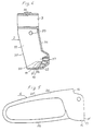
- Fig. 4 is a section through a part of the apparatus or a bracket portion in the apparatus seen from the side.
- Fig. 5 is a side elevation of a part of an apparatus or an operating portion in the apparatus which, in the form of a handle, stirrup, arm, lever or the like, is to be operated manually
- Fig. 6 is a side elevation, partly in section, of an apparatus according to Fig. 1, but in accordance with a slightly different embodiment.
- Reference numeral 1 in Figs. 1-3 designates one embodiment of an apparatus according to the invention which, according to the embodiment, is disposed on a vehicle or an implement 30, for example a rolling walker, and on its handle or grip portion 31 in connection with a gripping handle 32.
- the apparatus 1 is provided as a brake handle and is to impart a movement to a brake disposed on the implement for actuating the brake for braking the wheels of the implement.
- the brake may consist of a cable brake.
- the apparatus 1 shown in illustrated embodiment includes a bracket 2 which is intended to carry the apparatus 1 and hold the apparatus 1 to an implement 30 or the like or to the substrate on which the apparatus is to be active and displays a mounting device 3 for mounting the apparatus 1 to the implement 30, the substrate or the like.
- the mounting device 3 may consist of a clamping member or other anchorage means or, according to the embodiment, a tube length of one piece construction with the bracket 2 which can be passed on a tubular portion and secured by means of fixing devices such as a screw through the hole 36 in the mounting device 3.
- the apparatus 1 further includes an operating device 4 which is to be actuated for operating the apparatus 1 and actuation of the brake, and a connecting device 5 between the operating device 4 and the brake for imparting to the brake and for actuation thereof the commands or operations controlled by the operating device.
- the connecting device 5 consists of an element 6 in the form of a link, and a coupling device 7 in the form of a cable, line, wire or the like which is disposed to extend between the apparatus 1 and the brake or its regulator.
- the coupling device 7 is, in the apparatus 1, connected and secured to a part 8 of the element 6 or in its one end portion.
- the element 6 is rotatably journalled in the apparatus 1 or the bracket 2 in pivot 9, shaft or the like which extends through the other end portion of the element 6 and is journalled in the bracket 2 or its side walls 33.
- the operating device 4 is rotatably journalled in the element 6 in a second pivot 10, shaft or the like.
- the opposing portion in the bracket 2 is open and forms an aperture 35 or an open side through which the operating device 4 can extend for convenient access.
- the bracket 2 which is designed as a housing for protecting and partly covering the apparatus 1 and in whose side walls 33 there is a journal point 29 for the first pivot 9.
- the journal points 29 may consist of apertures or holes extending through the side walls 33, annular journal flanges or other journal types.
- a stop 22 which displays a first abutment 18 and a second abutment 20 between which extends a surface 19 or sliding surface for the operating device 4 and which may be designed as a convex surface, be curved, display planar portions with a curve, bend, radius or a preferably rounded edge 21.
- the stop 22 consists of an individual body which is disposable in the bracket 2 and which can be replaced by one or more other corresponding bodies with first and second abutments 18, 20, surface 19 or sliding surface and, where applicable, rounded edge 21, curve, bend or the like of a different extent, angle, positioning or the like and/or of a different dimension.
- a stop 22 is shown as one example in Fig. 6.
- the operating device 4 is shown which is to display an arm or a lever which must be capable of being grasped.
- the operating device 4 is designed as a handle 24 in the form of a stirrup with a first arm 25 and a second arm 26, operation of the operating device 4 being thereby facilitated.
- the operating device 4 is thus disposed in or at the apparatus 1 by being anchored in a rotary connection with the element 6 in the second pivot 10 which is disposed to project out from the side surfaces of the element 6 and/or extend through the element 6.
- the element 6 is disposed in or at the apparatus 1 by, as mentioned, being anchored in a rotary connection between the bracket 2 or its side walls 33. Transfer of operations from the operating device 4 to the brake or its regulator is thus effected via the element 6 and the coupling device 7, i.e. via the connection arrangement 5 or 6 and 7.
- the operating device 4 or the handle 24 is, according to the illustrated embodiment, disposed to be actuated by means of the fingers of one hand, which may grasp about the first arm 25 which is drawn towards the hand on braking or when the apparatus is to assume a second position 12, see Fig. 2.
- the handle 24 is to be moved or actuated so as to move in the opposite direction, which may be effected in that the fingers are placed on the one side of the first arm 25 and the handle 24, or the first arm 25 is pressed in a direction away from the hand.
- the operating device 4 or the handle 24 is, according to one embodiment, designed with a second arm 26, it being possible, on assuming said third position 13, to cause the fingers to press against the second arm 26 so that the handle 24 is rotated in a direction away from the hand.
- the operating device 4 is further designed with a first abutment 14 or abutment surface disposed to be able to abut against the element 6 and an abutment portion 17, or in the form of an edge between a second and third abutment 15, respectively 16, abutment surfaces, defining edges or defining surfaces of the operating device 4, see Fig. 5.
- the apparatus 1 is in a first position 11 or rest position which is a normal position and a disengaged position for the brake, i.e. the brake does not act upon the wheel for braking the wheel.
- the apparatus 1 is kept in this position by the loading or traction force with which the brake or a spring included in the brake regulator acts on the apparatus, as shown by the arrow 23.
- the operating device 4 abuts, in such instance, with its second abutment 15 against the first abutment 18 of the bracket 2 and with its first abutment 14 against the element 6.
- the element 6 is kept in a starting position.
- the further movement of the operating device 4 and the element 6 in said loading direction 23 is thus restricted.
- the operating device 4 and the element 6 can only be brought to movement or rotation by actuation on the handle 24 in that this is twisted in a direction towards the gripping handle 32 of the implement 30 or from the gripping handle 32.
- the apparatus 1 is in a second position 12 or first operative position, which is a braking position or instantaneous braking position for the brake, i.e. the brake actuates the wheel for braking effect on the wheel.
- the apparatus 1 is kept in this position in that the handle 24 is actuated so as to assume a rotated position in a direction towards the gripping handle 32 of the implement 30 or by a manual grip - or, more precisely, a grip with the fingers of the hand about the first arm 25 of the handle 24 and drawing of the operating device 4 in a direction towards the gripping handle 32 of the implement and, in such instance, overcoming the said loading on the apparatus 1.
- the operating device 4 is secured with the element 6 and the element 6 in its turn with the bracket 2 and abuts with its first abutment 14 against the element 6 in the first position 11 and during the rotation movement of the operating device 4, the operating device 4 and the element 6 will rotate together about the first pivot 9.
- the operating device 4 and the element 6 can, in this situation, be considered as a rigid body.
- the coupling device 7 is drawn in a direction towards the apparatus 1.
- actuation of the operating device 4 ceases or the grip on the handle 24 is released, the apparatus 1 returns to the first position 11 and the operating device 4 and the element 6 to the starting position.
- the second abutment 15 and/or 17 of the operating device 4 will once again abut against the first abutment 18 of the stop 22.
- the apparatus 1 is in a third position 13 or a second operative position which is also a braking position, but is here intended as a parking position for the brake, i.e. that the brake acts on the wheel for braking the wheel, this braking effect being maintained without continuous actuation or grip of the handle 24 being necessary.
- the apparatus 1 is moved from the first position 11 to the third position 13 in that the handle 24 is moved in a direction from the gripping handle 32 of the implement 30 by actuation preferably on the second arm 26.
- the abutment portion 17 or said edge of the operating device 4 is, in such instance, caused to slide towards and along the sliding surface 19 of the stop 22 while the said loading on the apparatus 1 is overcome and while the operating device 4 rotates about or in the second pivot 10 and the element 6 about or in the first pivot 9.
- the second pivot 10 will simultaneously move along an arcuate or circular line in a direction from the end wall 34 of the bracket 2 along an arcuate or circular line in a direction from the end wall 34 of the bracket 2 or towards the aperture 35, see the arrow 28, and, in such instance, at least until such time as the operating device 4 or its abutment portion 17 have passed, for example, that part located most proximal the second pivot 10 or the said rounded edge 21 or the like on the stop 22, the operating device 4 and its abutment portion 17 being moved along the sliding surface 19 of the stop 22 in a direction towards the second abutment 20 of the stop 22.
- the abutment portion 17 of the operating device 4 will abut against the second abutment 20 of the stop 22 and, according to one embodiment of the apparatus 1 of the present invention, be located in the transition between the sliding surface 19 of the stop 22 and the second abutment 20 of the stop 22. In such instance, the apparatus 1 will be located in the said third position 13.
- the apparatus 1 or the operating device 4 has passed a dead point and is retained continuously in the third position 13 without any external actuation needing to be maintained on the operating device 4 or the handle 24.
- a continuous braking effect will now prevail on the wheel of the implement 30 as long as the operating device 4 or the apparatus 1 is located in this third position 13.
- a third abutment 16 or abutment surface can, in this instance, come to rest against the sliding surface 19 of the stop 22 in association with the second abutment 20 of the stop 22.
- the operating device 4 is caused, or by actuation or grip on its handle 24 or first arm 25, to rotate in a direction towards the gripping handle 32 of the implement 30 and at least until such time as the abutment portion 17 of the operating device 4 has passed the dead point during its sliding along the sliding surface 19 of the stop 22, whereafter the apparatus 1 or the operating device 4 once again assumes the first position 11.
- the apparatus 1 comprises the element 6 in the form of a relatively elongate body or link whose one end portion is rotatably journalled in the apparatus 1 or the bracket 2 and the connecting portion 8 is located in its other end portion
- a long stroke length can be achieved in the coupling device 7 with relatively slight rotation of the operating device 4 or the handle which is journalled in the element 6 between these both said end portions or preferably closer to the centre of rotation of the first link 9 than the connection of the coupling device 7 in or at the element 6.
- less force is required than is normally the case in this type of apparatus for operating the handle 24, which is also because of the fulcrum principle which can be utilized and is utilized in the apparatus 1 as a result of the presence of the element 6, etc.
- the first abutment of the stop may consist of a planar surface which, via a more or less rounded edge or with an adapted radius, merges into the continuation or a second portion of the sliding surface to the second stop, which may consist of only a second portion of the sliding surface of the second stop which may consist of only an edge or surface in the stop of an extent deviating from the sliding surface or, for example, an extent approximately corresponding to the surface of the first stop or between approximately 75° - 125° to the immediately proximal sliding surface.
- the mounting device of the bracket may be of different type and the handle of the operating device may display another design even if that illustrated and described is of advantageous design.
- the said first arm of the handle is of an extent which is located in the proximity of the centre of rotation of the first pivot or between the first pivot and the second pivot, i.e. at a relatively large distance from the connecting portion of the element to the coupling device.
Landscapes
- Engineering & Computer Science (AREA)
- Mechanical Engineering (AREA)
- Transportation (AREA)
- Health & Medical Sciences (AREA)
- Physical Education & Sports Medicine (AREA)
- Pain & Pain Management (AREA)
- Epidemiology (AREA)
- Rehabilitation Therapy (AREA)
- Life Sciences & Earth Sciences (AREA)
- Animal Behavior & Ethology (AREA)
- General Health & Medical Sciences (AREA)
- Public Health (AREA)
- Veterinary Medicine (AREA)
- Braking Elements And Transmission Devices (AREA)
- Mechanical Control Devices (AREA)
- Handcart (AREA)
- Valve Device For Special Equipments (AREA)
- Toys (AREA)
- Push-Button Switches (AREA)
- Accommodation For Nursing Or Treatment Tables (AREA)
- Fluid-Driven Valves (AREA)
- Actuator (AREA)
- Electrical Discharge Machining, Electrochemical Machining, And Combined Machining (AREA)
- Surgical Instruments (AREA)
- Lock And Its Accessories (AREA)
- Glass Compositions (AREA)
- Reciprocating, Oscillating Or Vibrating Motors (AREA)
- Vehicle Body Suspensions (AREA)
- Switches With Compound Operations (AREA)
- Toilet Supplies (AREA)
- Medicines Containing Material From Animals Or Micro-Organisms (AREA)
- Manufacture Of Tobacco Products (AREA)
- Preparation Of Compounds By Using Micro-Organisms (AREA)
Abstract
Description
- The present invention relates to an apparatus for imparting a movement to and actuating an object and comprises a bracket with an operating device, preferably in the form of a handle, stirrup, arm or lever and which is disposed in connection with the object via connection devices. The object may, for example, consist of a brake for a wheel on a vehicle, implement or other wheeled apparatus.
- Such an actuating apparatus or regulator may be employed within a multiplicity of different fields, for example, for triggering or operating an apparatus, an object such as the exemplified brake, a contactor or for tightening a line or other elongate object. On occasions, such apparatuses are provided for being able to actuate an object or the like to assume two different operative positions.
- An apparatus of this general kind is known from DE-A 1 803 891 which discloses a device for operating an object, which apparatus comprises a bracket with an operating device which is pivotally disposed in relation to the bracket via a connecting device, said connecting device being in the form of an element which is rotatably disposed in the bracket about a first pivot, a coupling device being disposed between the element and the object, said operating device further including a first abutment for cooperation with the element. This device presents the features recited in the introductory part of
claim 1 annexed hereto. - In this prior-art device which is designed for actuation of the brake as well as of the throttle valve of motorbikes, the operating device, referred to as a brake lever, is used to simultaneously actuate the throttle and the brake. The lever may be set in different positions for normal speed, slow speed, and braking.
- However, there is no possibility of fixing the operating device or brake lever in the brake-application position, omitting the need for the user to continuously exert a force on the operating device in order to keep the brake operative. Nor are any means provided to allow adjustment of the force required to actuate the lever or operating device to the strength of the user.
- There is, however, a need for such an apparatus. The apparatus should be simple to handle, also by people that suffer from restricted powers of movement, in particular in the hands and/or suffer from reduced strength in the hands. Furthermore, there is a need in such apparatuses to be able to cause the apparatus to assume a position of rest in an operative position, i.e. in a position in which the apparatus causes a working moment to be executed, and in which actuation must thus be maintained without handling of the apparatus being necessary. Another desirable need in the art is to be able to maintain, with reduced handling movement, a long or necessary stroke length for obtaining the desired effect. It should be possible to move an apparatus of the type in question to a position for actuating an object to assume an operative position and maintain the position without the apparatus needing to be actuated before the above-mentioned operative position is to be triggered. A further need is for such an apparatus, where applicable, to be capable of being operated simply with non-precision motoricity in the movements of the hand or fingers.
- In, for example, a handbrake, the brake regulator must be pulled on during the entire time when braking effect is to be maintained. Such a design of a brake or an operating device therefor is sufficient in many cases. In other cases, it would be an advantage if a braking effect could be maintained without the need for a brake regulator to be operated during the time when it is desired to maintain the braking effect. This is particularly desirable in such brakes in which, where applicable, braking effect is to be maintained during a relatively long period of time and are moreover mounted in, for example, vehicles or implements which are to be used by people suffering from partial handicap or with reduced strength, in particular in the hands. Rolling walkers or walking frames are examples of such equipment which, moreover, are employed by people suffering from some form of movement handicap. The user of a rolling walker often needs to brake the rolling walker while walking, which is effected using an instantaneously operating brake. In lengthy stoppages when the user needs support of the rolling walker or when the user uses the rolling walker to sit on when taking a rest, it would be desirable if the apparatus could be realized for achieving a parking brake position, i.e. that the braking effect is maintained without the user needing to handle the apparatus, its operating device or a brake regulator during that time when the braking position is to be maintained. Such a parking brake position can also be utilized while walking, when braking needs to be effected during a relatively lengthy time, for example when negotiating a descent. In handbrakes with brake regulators for manual activation, that hand movement which must be executed is relatively long for achieving the necessary stroke length for satisfactory application of the brake. Furthermore, an unnecessarily large force is also required for achieving a satisfactory braking effect.
- In an apparatus according to the present invention, the set requirements are satisfied at the same time as the drawbacks inherent in prior art apparatuses are obviated. Thus, the apparatus is easy to operate, requires less movement capability and force on the part of the person operating the apparatus for achieving the intended effect and handling of the apparatus for actuating the object or the brake can be effected employing only non-precision motoricity. The apparatus is further designed to be able to assume at least one position in which the apparatus actuates the object to assume an operative position, and retains the object during that time in the operative position. In the said position of the apparatus, the apparatus will remain in a stable position, the rest position, or in an assumed locked position, i.e. the apparatus remains in that position until such time as a new operation, actuation or command is made. Moreover, the apparatus is designed in such a manner that a smaller or shorter operative movement need be carried out for achieving the necessary stroke length for imparting the movement or actuation to the object which is to be actuated. Furthermore, the apparatus can be designed with simple means to be adaptable according to those individual user's needs, which thus entails an individual adaptation or increased adaptation in individual cases. The apparatus moreover displays such a design that it can be manufactured in a simple manner and be correctly dimensioned, which achieves improved dependability as regards function and against wear and tear. An apparatus according to the present invention is, in this instance, characterized in that the connecting device includes an element which is rotatably disposed in the bracket about a first pivot, shaft or the like and which displays a connecting portion for a coupling device which is disposed in spaced apart relationship from the above-mentioned first pivot, and that the operating device is disposed in the apparatus in said element.
- According to one embodiment of the apparatus according to the invention, the operating device is disposed in the above-mentioned element between the first pivot and the connecting portion.
- According to a second embodiment of the apparatus according to the invention, the operating device is rotatably disposed in the above-mentioned element in a second pivot, shaft or the like and displays at least one first and one second abutment.
- According to yet a further embodiment of the apparatus according to the invention, the bracket displays a first abutment surface for the operating device, which abutment surface displays a defining edge against a second abutment surface for the operating device.
- In still a further embodiment of the apparatus according to the invention, the second pivot or shaft is anchored in the above-mentioned element and, together with the element, is disposed rotatably about the above-mentioned first pivot, and the operating device is rotatably disposed either about the first pivot or shaft and, in such instance, together with the element for assuming a second position, or about the second pivot or shaft for assuming a third position.
- According yet a further embodiment of the apparatus according to the invention, the apparatus is intended to be disposed in a first position or a rest position in which the object is intended to be in a first position and disposed, on handling or actuation, to be capable of assuming or being moved to a second position in which the object is brought to a second position or operative position, and further disposed, on handling or actuation, to be capable of assuming or being moved to a third position in which the object is also brought to the above-mentioned second position or operative position, in which, on assumption of the said second position, the operating device and said element are disposed to rotate about said first pivot and, on assuming said third position, the operating device is disposed to rotate about said second pivot, said element and said second pivot being disposed to rotate about said first pivot.
- In still a further embodiment of the apparatus according to the invention, the above-mentioned abutment surfaces and defining edge of the bracket are disposed on a body which is arranged to be disposable in the bracket and thereby is arranged to be replaceable by one or more other corresponding bodies with abutment surface, abutment surfaces and/or defining edge, of a different extent, angle, positioning or the like and/or a different dimension.
- Further characterizing features of and advantages inherent in the apparatus according to the present invention will be apparent from the following description of one embodiment of the apparatus, reference being made at the same time to the accompanying schematic Drawings in which Fig. 1 is a side elevation, partly in section, of an apparatus according to the invention, according to one embodiment, and in a first position or released position of the object, the apparatus being disposed on a vehicle, implement or the like and, in accordance with the illustrated example in connection to a handle, grip or the like displayed on the vehicle, implement or the like. Fig. 2 is a side elevation, partly in section, of the apparatus of Fig. 1 in a second position or an instantaneous brake position for the object, the apparatus being disposed on the same vehicle, implement or the like. Fig. 3 is a side elevation, partly in section, of the apparatus of Fig. 1 in a third position or a braking position for the object, but in this instance a locked braking position or so-called parking position. Fig. 4 is a section through a part of the apparatus or a bracket portion in the apparatus seen from the side. Fig. 5 is a side elevation of a part of an apparatus or an operating portion in the apparatus which, in the form of a handle, stirrup, arm, lever or the like, is to be operated manually, and Fig. 6 is a side elevation, partly in section, of an apparatus according to Fig. 1, but in accordance with a slightly different embodiment.
-
Reference numeral 1 in Figs. 1-3 designates one embodiment of an apparatus according to the invention which, according to the embodiment, is disposed on a vehicle or animplement 30, for example a rolling walker, and on its handle orgrip portion 31 in connection with agripping handle 32. In such instance, theapparatus 1 is provided as a brake handle and is to impart a movement to a brake disposed on the implement for actuating the brake for braking the wheels of the implement. The brake may consist of a cable brake. - The
apparatus 1 shown in illustrated embodiment includes abracket 2 which is intended to carry theapparatus 1 and hold theapparatus 1 to animplement 30 or the like or to the substrate on which the apparatus is to be active and displays amounting device 3 for mounting theapparatus 1 to theimplement 30, the substrate or the like. Themounting device 3 may consist of a clamping member or other anchorage means or, according to the embodiment, a tube length of one piece construction with thebracket 2 which can be passed on a tubular portion and secured by means of fixing devices such as a screw through thehole 36 in themounting device 3. Theapparatus 1 further includes anoperating device 4 which is to be actuated for operating theapparatus 1 and actuation of the brake, and a connectingdevice 5 between theoperating device 4 and the brake for imparting to the brake and for actuation thereof the commands or operations controlled by the operating device. The connectingdevice 5 consists of anelement 6 in the form of a link, and acoupling device 7 in the form of a cable, line, wire or the like which is disposed to extend between theapparatus 1 and the brake or its regulator. Thecoupling device 7 is, in theapparatus 1, connected and secured to apart 8 of theelement 6 or in its one end portion. Theelement 6 is rotatably journalled in theapparatus 1 or thebracket 2 inpivot 9, shaft or the like which extends through the other end portion of theelement 6 and is journalled in thebracket 2 or itsside walls 33. Theoperating device 4 is rotatably journalled in theelement 6 in asecond pivot 10, shaft or the like. In onefront wall 34 of thebracket 2, there is apassage 27 for thecoupling device 7. The opposing portion in thebracket 2 is open and forms anaperture 35 or an open side through which theoperating device 4 can extend for convenient access. - With further reference to Fig. 4, there is shown the
bracket 2 which is designed as a housing for protecting and partly covering theapparatus 1 and in whoseside walls 33 there is ajournal point 29 for thefirst pivot 9. Thejournal points 29 may consist of apertures or holes extending through theside walls 33, annular journal flanges or other journal types. In thebracket 2, there is further disposed astop 22 which displays afirst abutment 18 and asecond abutment 20 between which extends asurface 19 or sliding surface for theoperating device 4 and which may be designed as a convex surface, be curved, display planar portions with a curve, bend, radius or a preferably rounded edge 21. According to one embodiment of theapparatus 1 or thebracket 2, thestop 22 consists of an individual body which is disposable in thebracket 2 and which can be replaced by one or more other corresponding bodies with first andsecond abutments surface 19 or sliding surface and, where applicable, rounded edge 21, curve, bend or the like of a different extent, angle, positioning or the like and/or of a different dimension. Such astop 22 is shown as one example in Fig. 6. - With further reference to Fig. 5, the
operating device 4 is shown which is to display an arm or a lever which must be capable of being grasped. According to the illustrated embodiment, theoperating device 4 is designed as ahandle 24 in the form of a stirrup with afirst arm 25 and asecond arm 26, operation of theoperating device 4 being thereby facilitated. Theoperating device 4 is thus disposed in or at theapparatus 1 by being anchored in a rotary connection with theelement 6 in thesecond pivot 10 which is disposed to project out from the side surfaces of theelement 6 and/or extend through theelement 6. In turn, theelement 6 is disposed in or at theapparatus 1 by, as mentioned, being anchored in a rotary connection between thebracket 2 or itsside walls 33. Transfer of operations from the operatingdevice 4 to the brake or its regulator is thus effected via theelement 6 and thecoupling device 7, i.e. via theconnection arrangement - The operating
device 4 or thehandle 24 is, according to the illustrated embodiment, disposed to be actuated by means of the fingers of one hand, which may grasp about thefirst arm 25 which is drawn towards the hand on braking or when the apparatus is to assume asecond position 12, see Fig. 2. When the apparatus is to assume athird position 13, see Fig. 3, thehandle 24 is to be moved or actuated so as to move in the opposite direction, which may be effected in that the fingers are placed on the one side of thefirst arm 25 and thehandle 24, or thefirst arm 25 is pressed in a direction away from the hand. In order to avoid relocation of the fingers and assuming a new grip, the operatingdevice 4 or thehandle 24 is, according to one embodiment, designed with asecond arm 26, it being possible, on assuming saidthird position 13, to cause the fingers to press against thesecond arm 26 so that thehandle 24 is rotated in a direction away from the hand. - The operating
device 4 is further designed with afirst abutment 14 or abutment surface disposed to be able to abut against theelement 6 and anabutment portion 17, or in the form of an edge between a second andthird abutment 15, respectively 16, abutment surfaces, defining edges or defining surfaces of theoperating device 4, see Fig. 5. - In Fig. 1, the
apparatus 1 is in afirst position 11 or rest position which is a normal position and a disengaged position for the brake, i.e. the brake does not act upon the wheel for braking the wheel. Theapparatus 1 is kept in this position by the loading or traction force with which the brake or a spring included in the brake regulator acts on the apparatus, as shown by thearrow 23. The operatingdevice 4 abuts, in such instance, with itssecond abutment 15 against thefirst abutment 18 of thebracket 2 and with itsfirst abutment 14 against theelement 6. As a result of the said loading and the abutment of theoperating device 4 against thefirst abutment 18 of thebracket 2 or thestop 22 and the abutment of theelement 6 against thefirst abutment 14 of theoperating device 4, theelement 6 is kept in a starting position. In thisfirst position 11 of theapparatus 1, the further movement of theoperating device 4 and theelement 6 in saidloading direction 23 is thus restricted. In such instance, the operatingdevice 4 and theelement 6 can only be brought to movement or rotation by actuation on thehandle 24 in that this is twisted in a direction towards the grippinghandle 32 of the implement 30 or from thegripping handle 32. - In Fig. 2, the
apparatus 1 is in asecond position 12 or first operative position, which is a braking position or instantaneous braking position for the brake, i.e. the brake actuates the wheel for braking effect on the wheel. Theapparatus 1 is kept in this position in that thehandle 24 is actuated so as to assume a rotated position in a direction towards the grippinghandle 32 of the implement 30 or by a manual grip - or, more precisely, a grip with the fingers of the hand about thefirst arm 25 of thehandle 24 and drawing of theoperating device 4 in a direction towards the grippinghandle 32 of the implement and, in such instance, overcoming the said loading on theapparatus 1. In that theoperating device 4 is secured with theelement 6 and theelement 6 in its turn with thebracket 2 and abuts with itsfirst abutment 14 against theelement 6 in thefirst position 11 and during the rotation movement of theoperating device 4, the operatingdevice 4 and theelement 6 will rotate together about thefirst pivot 9. The operatingdevice 4 and theelement 6 can, in this situation, be considered as a rigid body. Thecoupling device 7 is drawn in a direction towards theapparatus 1. When actuation of theoperating device 4 ceases or the grip on thehandle 24 is released, theapparatus 1 returns to thefirst position 11 and theoperating device 4 and theelement 6 to the starting position. Thesecond abutment 15 and/or 17 of theoperating device 4 will once again abut against thefirst abutment 18 of thestop 22. - In Fig. 3, the
apparatus 1 is in athird position 13 or a second operative position which is also a braking position, but is here intended as a parking position for the brake, i.e. that the brake acts on the wheel for braking the wheel, this braking effect being maintained without continuous actuation or grip of thehandle 24 being necessary. Theapparatus 1 is moved from thefirst position 11 to thethird position 13 in that thehandle 24 is moved in a direction from thegripping handle 32 of the implement 30 by actuation preferably on thesecond arm 26. Theabutment portion 17 or said edge of theoperating device 4 is, in such instance, caused to slide towards and along the slidingsurface 19 of thestop 22 while the said loading on theapparatus 1 is overcome and while theoperating device 4 rotates about or in thesecond pivot 10 and theelement 6 about or in thefirst pivot 9. Thesecond pivot 10 will simultaneously move along an arcuate or circular line in a direction from theend wall 34 of thebracket 2 along an arcuate or circular line in a direction from theend wall 34 of thebracket 2 or towards theaperture 35, see thearrow 28, and, in such instance, at least until such time as theoperating device 4 or itsabutment portion 17 have passed, for example, that part located most proximal thesecond pivot 10 or the said rounded edge 21 or the like on thestop 22, the operatingdevice 4 and itsabutment portion 17 being moved along the slidingsurface 19 of thestop 22 in a direction towards thesecond abutment 20 of thestop 22. Theabutment portion 17 of theoperating device 4 will abut against thesecond abutment 20 of thestop 22 and, according to one embodiment of theapparatus 1 of the present invention, be located in the transition between the slidingsurface 19 of thestop 22 and thesecond abutment 20 of thestop 22. In such instance, theapparatus 1 will be located in the saidthird position 13. During the movement along the slidingsurface 19 of thestop 22, theapparatus 1 or theoperating device 4 has passed a dead point and is retained continuously in thethird position 13 without any external actuation needing to be maintained on theoperating device 4 or thehandle 24. A continuous braking effect will now prevail on the wheel of the implement 30 as long as theoperating device 4 or theapparatus 1 is located in thisthird position 13. Athird abutment 16 or abutment surface can, in this instance, come to rest against the slidingsurface 19 of thestop 22 in association with thesecond abutment 20 of thestop 22. When theapparatus 1 is to be released from the assumedthird position 13, i.e. when it is desired to cancel the braking effect, the operatingdevice 4 is caused, or by actuation or grip on itshandle 24 orfirst arm 25, to rotate in a direction towards the grippinghandle 32 of the implement 30 and at least until such time as theabutment portion 17 of theoperating device 4 has passed the dead point during its sliding along the slidingsurface 19 of thestop 22, whereafter theapparatus 1 or theoperating device 4 once again assumes thefirst position 11. - Given that the
apparatus 1 comprises theelement 6 in the form of a relatively elongate body or link whose one end portion is rotatably journalled in theapparatus 1 or thebracket 2 and the connectingportion 8 is located in its other end portion, a long stroke length can be achieved in thecoupling device 7 with relatively slight rotation of theoperating device 4 or the handle which is journalled in theelement 6 between these both said end portions or preferably closer to the centre of rotation of thefirst link 9 than the connection of thecoupling device 7 in or at theelement 6. Furthermore, less force is required than is normally the case in this type of apparatus for operating thehandle 24, which is also because of the fulcrum principle which can be utilized and is utilized in theapparatus 1 as a result of the presence of theelement 6, etc. - Without departing from the scope of the inventive concept as herein disclosed, modifications of the apparatus disclosed by way of the preferred embodiment are conceivable. Thus, the first abutment of the stop may consist of a planar surface which, via a more or less rounded edge or with an adapted radius, merges into the continuation or a second portion of the sliding surface to the second stop, which may consist of only a second portion of the sliding surface of the second stop which may consist of only an edge or surface in the stop of an extent deviating from the sliding surface or, for example, an extent approximately corresponding to the surface of the first stop or between approximately 75° - 125° to the immediately proximal sliding surface. Furthermore, the mounting device of the bracket may be of different type and the handle of the operating device may display another design even if that illustrated and described is of advantageous design. In such instance, it might also be noted that the said first arm of the handle is of an extent which is located in the proximity of the centre of rotation of the first pivot or between the first pivot and the second pivot, i.e. at a relatively large distance from the connecting portion of the element to the coupling device. The apparatus according to the invention is thus not restricted to that which has been illustrated and described in connection with the embodiments, but only by the appended Claims.
Claims (4)
- Apparatus for operating an object, which apparatus comprises a bracket (2) with an operating device (4) which is pivotally disposed in relation to the bracket (2) via a connecting device (5), said connecting device (5) being in the form of an element (6) which is rotatably disposed in the bracket (2) about a first pivot (9), a coupling device (7) being disposed between the element (6) and the object; said operating device (4) further including a first abutment (14) for cooperation with the element (6), characterized in that the operating device (4) is pivotally disposed on the element (6) about a second pivot (10) and in that it is formed with a second abutment (17) for cooperation with the bracket (2).
- Apparatus according to claim 1, characterized in that the first abutment (14) on the operating device (4) is arranged to cooperate with the element (6) for pivoting the element (6) by means of the operating device (4) about the first pivot (9) to a second position (12).
- Apparatus according to claim 1 or 2, characterized in that the bracket (2) is formed with a first abutment (18), with a second abutment (20), and with a face (19) or sliding surface extending between said abutments for cooperation with the second abutment (17) on the operating device (4) for pivoting the element (6) about the first pivot (9) by means of the operating device (4) and the second pivot (10) to a third position (13).
- Apparatus according to any one of the preceding claims, characterized in that a stop member (22) in the form of a separate body may be positioned in the bracket (2), said body being replaceable by one or more other stop members (22) having other dimensions, differently positioned abutments (18, 20), a different extent of the sliding surface (19) between said abutments (18, 20) a different radius, curvature or the like of the sliding surface (19) or a rounded edge (21) located along the sliding edge (19), and/or a different position for the said rounded edge (21).
Applications Claiming Priority (3)
| Application Number | Priority Date | Filing Date | Title |
|---|---|---|---|
| SE9200906A SE500410C2 (en) | 1992-03-24 | 1992-03-24 | Walking trolley hand brake control - has normal application and release positions plus mechanism to hold on brake if lever is pushed downwards |
| SE9200906 | 1992-03-24 | ||
| PCT/SE1993/000235 WO1993018946A1 (en) | 1992-03-24 | 1993-03-19 | An apparatus for actuating |
Publications (2)
| Publication Number | Publication Date |
|---|---|
| EP0638032A1 EP0638032A1 (en) | 1995-02-15 |
| EP0638032B1 true EP0638032B1 (en) | 1997-05-14 |
Family
ID=20385721
Family Applications (1)
| Application Number | Title | Priority Date | Filing Date |
|---|---|---|---|
| EP93908215A Expired - Lifetime EP0638032B1 (en) | 1992-03-24 | 1993-03-19 | An apparatus for actuating |
Country Status (14)
| Country | Link |
|---|---|
| US (1) | US5279180A (en) |
| EP (1) | EP0638032B1 (en) |
| JP (1) | JP2576823B2 (en) |
| AT (1) | ATE152978T1 (en) |
| AU (1) | AU3911393A (en) |
| CA (1) | CA2090448C (en) |
| DE (2) | DE69310729T2 (en) |
| DK (1) | DK0638032T3 (en) |
| ES (1) | ES2066745T3 (en) |
| FI (1) | FI111828B (en) |
| GR (1) | GR950300020T1 (en) |
| NO (1) | NO302348B1 (en) |
| SE (1) | SE500410C2 (en) |
| WO (1) | WO1993018946A1 (en) |
Families Citing this family (57)
| Publication number | Priority date | Publication date | Assignee | Title |
|---|---|---|---|---|
| US5924328A (en) * | 1994-04-22 | 1999-07-20 | Shimano, Inc. | Braking device for bicycles |
| AU5332796A (en) * | 1995-04-03 | 1996-10-23 | Care Dimension A/S | Brake actuating mechanism |
| US5664460A (en) * | 1995-11-13 | 1997-09-09 | Foreign Developments Limited | Cable controller |
| DE19636587C1 (en) * | 1996-09-09 | 1998-01-22 | Doescher Handels Kg Geraetebau | Operating device, especially for brake |
| DE19723151C1 (en) * | 1997-06-03 | 1998-09-24 | Casagarden Gmbh & Co Kg Reha P | Hand-operated brake lever with parking device esp for vehicle-trainer |
| US5878625A (en) * | 1997-07-18 | 1999-03-09 | Fong Hsiang Metal Industry Co., Ltd. | Brake actuating device |
| CA2210836C (en) * | 1997-07-18 | 2000-07-11 | Nai Shing Hu | Actuating device |
| US5896779A (en) * | 1997-08-01 | 1999-04-27 | Sunrise Medical Hhg Inc. | Dual mode brake actuator for walker |
| GB2328495A (en) * | 1997-08-20 | 1999-02-24 | Apex Medical Corp | Braking structure for a rehabilitation trolley |
| US5927441A (en) * | 1997-09-23 | 1999-07-27 | Luo; Chung-I | Braking device for trolley |
| US5865065A (en) * | 1997-10-01 | 1999-02-02 | Valentine International Limited | Hand brake for a wheeled walker |
| US6047611A (en) | 1997-12-01 | 2000-04-11 | Warren Vincent M. | Collapsible control lever |
| US20120006146A1 (en) * | 1997-12-01 | 2012-01-12 | Warren Vincent M | Collapsible control lever |
| US6079290A (en) * | 1999-02-02 | 2000-06-27 | Li; Charles | Rollator braking device |
| SE514269C2 (en) * | 1999-04-26 | 2001-01-29 | Etac Ab | Brake device for rollators |
| US6202502B1 (en) * | 1999-04-27 | 2001-03-20 | Genemax Medical Products Industry Corp. | Brake mechanism for auxiliary walker |
| US6098487A (en) * | 1999-06-25 | 2000-08-08 | Frank Fang | Hand brake for a wheeled walker |
| US7921747B2 (en) * | 1999-07-15 | 2011-04-12 | Barnett Robert L | Collapsible control lever |
| US6393936B1 (en) * | 1999-07-15 | 2002-05-28 | Robert L. Barnett | Collapsible control lever |
| US6032765A (en) * | 1999-08-09 | 2000-03-07 | Larmine Manufacturing Corp. | Brake control device for a wheeled walker |
| US6216825B1 (en) * | 1999-08-16 | 2001-04-17 | Chih-Cheng Hung | Brake mechanism |
| US6192772B1 (en) * | 1999-09-03 | 2001-02-27 | Shih-Yi Huang | Controller for the brake of a rolling walkkit |
| TW455489B (en) | 1999-10-12 | 2001-09-21 | Takano Co Ltd | Rolling walker |
| GB0020402D0 (en) * | 2000-08-19 | 2000-10-04 | Meritor Light Vehicle Sys Ltd | A handle arrangement |
| EP1317237B1 (en) | 2000-09-12 | 2007-10-31 | Random Products Trust | Wheeled walker |
| US7219906B2 (en) * | 2000-09-12 | 2007-05-22 | Random Products In Trust | Height-adjustable cordless brake |
| CA2318028C (en) * | 2000-09-12 | 2005-08-09 | Random Products Trust | Combination walker and transport chair |
| US6739133B2 (en) | 2001-12-03 | 2004-05-25 | Robert L. Barnett | Motorcycle control lever |
| US20040020322A1 (en) * | 2002-07-31 | 2004-02-05 | Yu-Chi Hsieh | Brake handle structure for mobility aid |
| US6647825B1 (en) * | 2003-01-17 | 2003-11-18 | Ching-Hsu Lin | Hand brake device |
| SE526802C2 (en) * | 2004-03-25 | 2005-11-08 | Volaris Sweden Ab | Device and method of operating a brake of a walker |
| JP4582323B2 (en) * | 2005-03-24 | 2010-11-17 | 株式会社松永製作所 | Brake grip device |
| US8926959B2 (en) * | 2005-07-22 | 2015-01-06 | The Board Of Trustees Of The Leland Stanford Junior University | System for optical stimulation of target cells |
| USD592819S1 (en) | 2007-05-03 | 2009-05-19 | Johnsondiversey, Inc. | Valve assembly for a floor maintenance tool |
| USD602664S1 (en) | 2007-05-03 | 2009-10-20 | Johnsondiversey, Inc. | Floor maintenance tool |
| USD590117S1 (en) | 2007-05-03 | 2009-04-07 | Johnsondiversey, Inc. | Floor maintenance tool |
| JP2009149210A (en) * | 2007-12-20 | 2009-07-09 | Shimano Inc | Operating device for bicycle |
| US9022413B2 (en) | 2008-10-08 | 2015-05-05 | Evolution Technologies Inc. | Foldable walker apparatus |
| US8083239B2 (en) | 2008-10-08 | 2011-12-27 | Evolution Technologies Inc. | Foldable walker apparatus |
| US8602424B2 (en) | 2008-10-08 | 2013-12-10 | Evolution Technologies, Inc. | Foldable walker apparatus |
| US8936256B2 (en) | 2008-10-08 | 2015-01-20 | Evolution Technologies Inc. | Foldable walker apparatus |
| TW201200985A (en) | 2009-12-28 | 2012-01-01 | Max Co Ltd | Operating mechanism and assistive equipment |
| JP5471566B2 (en) * | 2010-02-17 | 2014-04-16 | マックス株式会社 | Operation mechanism and life support tool |
| US8573613B2 (en) | 2010-10-29 | 2013-11-05 | Evolution Technologies Inc. | Foldable walker apparatus |
| US8505936B2 (en) | 2010-10-29 | 2013-08-13 | Evolution Technologies Inc. | Foldable walker apparatus |
| US9415635B2 (en) | 2010-10-29 | 2016-08-16 | Evolution Technologies Inc. | Foldable walker apparatus |
| US9339432B2 (en) | 2014-02-28 | 2016-05-17 | Evolution Technologies Inc. | Walker apparatus and backrest therefor |
| US9744094B2 (en) | 2014-02-28 | 2017-08-29 | Evolution Technologies Inc. | Walker apparatus and backrest therefor |
| US10730489B2 (en) | 2015-09-02 | 2020-08-04 | Evolution Technologies Inc. | Brake assembly for height-adjustable patient transport apparatus |
| US11648922B2 (en) | 2015-09-02 | 2023-05-16 | Evolution Technologies Inc. | Manually-operated, height-adjustable wheeled vehicle, and a brake assembly and wheel fork assembly thereof |
| US10053062B2 (en) | 2015-09-02 | 2018-08-21 | Evolution Technologies Inc. | Brake assembly for a height-adjustable walker apparatus |
| CA167113S (en) | 2016-02-26 | 2017-12-27 | Julian Liu | Set of seat cushions |
| CA2936983A1 (en) * | 2016-07-22 | 2018-01-22 | Jean-Marc Landry | Smart-rollator with everyday life adapted chassis, fall detection system, automatic braking and anti-roll back systems, manufacturing method and usages thereof |
| CA173079S (en) | 2017-02-17 | 2017-12-27 | Evolution Tech Inc | Set of seat cushions |
| DE102018215479A1 (en) * | 2018-09-12 | 2020-03-12 | Asp Gmbh | Device for supporting the mobility of a person with reduced mobility |
| EP3912611A1 (en) | 2020-05-22 | 2021-11-24 | Invacare International GmbH | Foldable walking aid apparatus |
| JP7836084B2 (en) * | 2022-09-08 | 2026-03-26 | 三貴ホールディングス株式会社 | Brake mechanism |
Family Cites Families (16)
| Publication number | Priority date | Publication date | Assignee | Title |
|---|---|---|---|---|
| FR895963A (en) * | 1943-03-04 | 1945-02-08 | Improvements to remote control devices, especially for brakes | |
| GB680046A (en) * | 1950-06-30 | 1952-10-01 | Tan Sad Ltd | Improvements relating to brakes for invalid and like wheeled chairs |
| FR1061867A (en) * | 1952-04-21 | 1954-04-15 | Improvements to devices for the control of light motor vehicles, such as motor cycles | |
| FR1124891A (en) * | 1955-05-23 | 1956-10-19 | Self-locking control lever | |
| FR1552199A (en) * | 1967-11-22 | 1969-01-03 | ||
| FR2088847A5 (en) * | 1970-04-27 | 1972-01-07 | Couderc Lucien | |
| FR2598135A1 (en) * | 1986-05-05 | 1987-11-06 | Roudier Olivier | Brake or clutch hand lever for vehicles of the motorcycle type or similar |
| FR2620407B1 (en) * | 1987-09-10 | 1989-11-24 | Merle Pierre | TWO-POSITION BRAKE HANDLE FOR RACE HANDLEBAR |
| US4850241A (en) * | 1987-12-22 | 1989-07-25 | Hayes Industrial Brake, Inc. | Cable tension equalizer for a lever operated brake actuator |
| IT1219256B (en) * | 1988-05-02 | 1990-05-03 | Campagnolo Spa | ADJUSTABLE SUPPORT FOR CONTROL LEVERS TO BE MOUNTED ON A HANDLEBAR OF A MOTORCYCLE OR SIMILAR CYCLE |
| JPH0529996Y2 (en) * | 1988-07-15 | 1993-07-30 | ||
| US4899610A (en) * | 1988-09-28 | 1990-02-13 | Bombardier Inc. | Throttle lever |
| US4852697A (en) * | 1989-01-04 | 1989-08-01 | Helmut Kulik | Wheelchair handbrakes with actuator tube and replaceable brake stopper |
| JPH0415598Y2 (en) * | 1989-02-06 | 1992-04-08 | ||
| US5078023A (en) * | 1989-05-09 | 1992-01-07 | Scarborough Gary H | Thumb-operated throttle control |
| WO1990014974A2 (en) * | 1989-05-26 | 1990-12-13 | Bachmayr Alfred C Von | Actuator device for cable-actuated braking systems |
-
1992
- 1992-03-24 SE SE9200906A patent/SE500410C2/en not_active IP Right Cessation
-
1993
- 1993-02-26 CA CA002090448A patent/CA2090448C/en not_active Expired - Lifetime
- 1993-03-15 US US08/031,594 patent/US5279180A/en not_active Expired - Lifetime
- 1993-03-19 JP JP5515160A patent/JP2576823B2/en not_active Expired - Lifetime
- 1993-03-19 AT AT93908215T patent/ATE152978T1/en active
- 1993-03-19 ES ES93908215T patent/ES2066745T3/en not_active Expired - Lifetime
- 1993-03-19 DK DK93908215.2T patent/DK0638032T3/en active
- 1993-03-19 DE DE69310729T patent/DE69310729T2/en not_active Expired - Lifetime
- 1993-03-19 EP EP93908215A patent/EP0638032B1/en not_active Expired - Lifetime
- 1993-03-19 DE DE0638032T patent/DE638032T1/en active Pending
- 1993-03-19 AU AU39113/93A patent/AU3911393A/en not_active Abandoned
- 1993-03-19 WO PCT/SE1993/000235 patent/WO1993018946A1/en not_active Ceased
- 1993-10-13 FI FI934515A patent/FI111828B/en not_active IP Right Cessation
- 1993-11-08 NO NO934026A patent/NO302348B1/en not_active IP Right Cessation
-
1995
- 1995-06-30 GR GR950300020T patent/GR950300020T1/en unknown
Also Published As
| Publication number | Publication date |
|---|---|
| JP2576823B2 (en) | 1997-01-29 |
| US5279180A (en) | 1994-01-18 |
| DE69310729T2 (en) | 1997-12-11 |
| AU3911393A (en) | 1993-10-21 |
| NO934026D0 (en) | 1993-11-08 |
| FI934515L (en) | 1993-10-13 |
| DK0638032T3 (en) | 1997-06-30 |
| NO934026L (en) | 1993-11-08 |
| ATE152978T1 (en) | 1997-05-15 |
| ES2066745T3 (en) | 1997-07-01 |
| JPH07500791A (en) | 1995-01-26 |
| DE638032T1 (en) | 1995-08-24 |
| SE500410C2 (en) | 1994-06-20 |
| EP0638032A1 (en) | 1995-02-15 |
| CA2090448C (en) | 1994-04-19 |
| CA2090448A1 (en) | 1993-09-25 |
| NO302348B1 (en) | 1998-02-23 |
| SE9200906D0 (en) | 1992-03-24 |
| GR950300020T1 (en) | 1995-06-30 |
| ES2066745T1 (en) | 1995-03-16 |
| SE9200906L (en) | 1993-09-25 |
| FI934515A0 (en) | 1993-10-13 |
| DE69310729D1 (en) | 1997-06-19 |
| WO1993018946A1 (en) | 1993-09-30 |
| FI111828B (en) | 2003-09-30 |
Similar Documents
| Publication | Publication Date | Title |
|---|---|---|
| US5279180A (en) | Actuating device | |
| US5896779A (en) | Dual mode brake actuator for walker | |
| US5664460A (en) | Cable controller | |
| EP0435248B1 (en) | Brake control apparatus for bicycle | |
| KR970705490A (en) | CABLE SLACK ADJUSTER | |
| US4998983A (en) | Manually operated apparatus for controlling the brake and accelerator of a motor vehicle | |
| JPS6389102A (en) | Brake for fixing pull member of ski boots | |
| US5211072A (en) | Variable ratio park brake with slack adjust | |
| US4324309A (en) | Control system for legless operation of motor vehicles | |
| WO1992006661A1 (en) | Handbrake for wheeled vehicles | |
| CN119137035A (en) | Hydraulic brake integrated control unit for handlebar-guided vehicles | |
| US5159850A (en) | Parking-brake operating device | |
| EP0480108B1 (en) | Parking-brake operating device | |
| EP2340988A2 (en) | Operating mechanism and assistive equipment | |
| US5938685A (en) | Locking handle for surgical instruments | |
| JP2004503428A (en) | Parking brake | |
| JPH0578460B2 (en) | ||
| US4768622A (en) | Brake device with lever, crank, spring, and arm | |
| US7062988B2 (en) | Locking of a control device with a margin for adjustment | |
| JP2001526608A (en) | Safety brake mechanism for automobiles | |
| US12352329B2 (en) | Brake and freewheel arrangement for a manually maneuverable park and garden equipment | |
| JP2914509B2 (en) | Foot-operated parking brake device | |
| JPS647066Y2 (en) | ||
| JPH03200459A (en) | Parking braking device | |
| GB9709929D0 (en) | The sarah saver |
Legal Events
| Date | Code | Title | Description |
|---|---|---|---|
| PUAI | Public reference made under article 153(3) epc to a published international application that has entered the european phase |
Free format text: ORIGINAL CODE: 0009012 |
|
| 17P | Request for examination filed |
Effective date: 19940421 |
|
| AK | Designated contracting states |
Kind code of ref document: A1 Designated state(s): AT BE CH DE DK ES FR GB GR IT LI NL PT |
|
| ITCL | It: translation for ep claims filed |
Representative=s name: G.PETRAZ P.SSO GLP S.R.L. |
|
| TCAT | At: translation of patent claims filed | ||
| REG | Reference to a national code |
Ref country code: ES Ref legal event code: BA2A Ref document number: 2066745 Country of ref document: ES Kind code of ref document: T1 |
|
| EL | Fr: translation of claims filed | ||
| TCNL | Nl: translation of patent claims filed | ||
| DET | De: translation of patent claims | ||
| 17Q | First examination report despatched |
Effective date: 19950906 |
|
| GRAG | Despatch of communication of intention to grant |
Free format text: ORIGINAL CODE: EPIDOS AGRA |
|
| GRAH | Despatch of communication of intention to grant a patent |
Free format text: ORIGINAL CODE: EPIDOS IGRA |
|
| GRAH | Despatch of communication of intention to grant a patent |
Free format text: ORIGINAL CODE: EPIDOS IGRA |
|
| GRAA | (expected) grant |
Free format text: ORIGINAL CODE: 0009210 |
|
| ITF | It: translation for a ep patent filed | ||
| AK | Designated contracting states |
Kind code of ref document: B1 Designated state(s): AT BE CH DE DK ES FR GB GR IT LI NL PT |
|
| PG25 | Lapsed in a contracting state [announced via postgrant information from national office to epo] |
Ref country code: GR Free format text: LAPSE BECAUSE OF FAILURE TO SUBMIT A TRANSLATION OF THE DESCRIPTION OR TO PAY THE FEE WITHIN THE PRESCRIBED TIME-LIMIT Effective date: 19970514 |
|
| REF | Corresponds to: |
Ref document number: 152978 Country of ref document: AT Date of ref document: 19970515 Kind code of ref document: T |
|
| REG | Reference to a national code |
Ref country code: CH Ref legal event code: NV Representative=s name: R. A. EGLI & CO. PATENTANWAELTE Ref country code: CH Ref legal event code: EP |
|
| REF | Corresponds to: |
Ref document number: 69310729 Country of ref document: DE Date of ref document: 19970619 |
|
| REG | Reference to a national code |
Ref country code: DK Ref legal event code: T3 |
|
| REG | Reference to a national code |
Ref country code: ES Ref legal event code: FG2A Ref document number: 2066745 Country of ref document: ES Kind code of ref document: T3 |
|
| PG25 | Lapsed in a contracting state [announced via postgrant information from national office to epo] |
Ref country code: PT Effective date: 19970814 |
|
| ET | Fr: translation filed | ||
| PLBE | No opposition filed within time limit |
Free format text: ORIGINAL CODE: 0009261 |
|
| STAA | Information on the status of an ep patent application or granted ep patent |
Free format text: STATUS: NO OPPOSITION FILED WITHIN TIME LIMIT |
|
| 26N | No opposition filed | ||
| REG | Reference to a national code |
Ref country code: CH Ref legal event code: PUE Owner name: DOLOMITE SVENSKA AKTIEBOLAG TRANSFER- DOLOMITE AB |
|
| REG | Reference to a national code |
Ref country code: GB Ref legal event code: 732E |
|
| REG | Reference to a national code |
Ref country code: GB Ref legal event code: IF02 |
|
| NLS | Nl: assignments of ep-patents |
Owner name: DOLOMITE SVENSKA AKTIEBOLAG |
|
| REG | Reference to a national code |
Ref country code: FR Ref legal event code: TP |
|
| REG | Reference to a national code |
Ref country code: ES Ref legal event code: PC2A |
|
| PG25 | Lapsed in a contracting state [announced via postgrant information from national office to epo] |
Ref country code: IT Free format text: LAPSE BECAUSE OF NON-PAYMENT OF DUE FEES;WARNING: LAPSES OF ITALIAN PATENTS WITH EFFECTIVE DATE BEFORE 2007 MAY HAVE OCCURRED AT ANY TIME BEFORE 2007. THE CORRECT EFFECTIVE DATE MAY BE DIFFERENT FROM THE ONE RECORDED. Effective date: 20050319 |
|
| PGRI | Patent reinstated in contracting state [announced from national office to epo] |
Ref country code: IT Effective date: 20091201 |
|
| PGFP | Annual fee paid to national office [announced via postgrant information from national office to epo] |
Ref country code: IT Payment date: 20110319 Year of fee payment: 19 Ref country code: AT Payment date: 20110307 Year of fee payment: 19 Ref country code: CH Payment date: 20110304 Year of fee payment: 19 |
|
| PGFP | Annual fee paid to national office [announced via postgrant information from national office to epo] |
Ref country code: ES Payment date: 20110325 Year of fee payment: 19 Ref country code: BE Payment date: 20110304 Year of fee payment: 19 |
|
| PGFP | Annual fee paid to national office [announced via postgrant information from national office to epo] |
Ref country code: NL Payment date: 20110405 Year of fee payment: 19 |
|
| PGFP | Annual fee paid to national office [announced via postgrant information from national office to epo] |
Ref country code: FR Payment date: 20120326 Year of fee payment: 20 |
|
| PGFP | Annual fee paid to national office [announced via postgrant information from national office to epo] |
Ref country code: DE Payment date: 20120305 Year of fee payment: 20 |
|
| PGFP | Annual fee paid to national office [announced via postgrant information from national office to epo] |
Ref country code: GB Payment date: 20120306 Year of fee payment: 20 Ref country code: DK Payment date: 20120302 Year of fee payment: 20 |
|
| BERE | Be: lapsed |
Owner name: *DOLOMITE A.B. Effective date: 20120331 |
|
| REG | Reference to a national code |
Ref country code: NL Ref legal event code: V1 Effective date: 20121001 |
|
| REG | Reference to a national code |
Ref country code: CH Ref legal event code: PL |
|
| REG | Reference to a national code |
Ref country code: AT Ref legal event code: MM01 Ref document number: 152978 Country of ref document: AT Kind code of ref document: T Effective date: 20120319 |
|
| PG25 | Lapsed in a contracting state [announced via postgrant information from national office to epo] |
Ref country code: AT Free format text: LAPSE BECAUSE OF NON-PAYMENT OF DUE FEES Effective date: 20120319 Ref country code: BE Free format text: LAPSE BECAUSE OF NON-PAYMENT OF DUE FEES Effective date: 20120331 Ref country code: CH Free format text: LAPSE BECAUSE OF NON-PAYMENT OF DUE FEES Effective date: 20120331 Ref country code: LI Free format text: LAPSE BECAUSE OF NON-PAYMENT OF DUE FEES Effective date: 20120331 |
|
| PG25 | Lapsed in a contracting state [announced via postgrant information from national office to epo] |
Ref country code: IT Free format text: LAPSE BECAUSE OF NON-PAYMENT OF DUE FEES Effective date: 20120319 |
|
| REG | Reference to a national code |
Ref country code: DE Ref legal event code: R071 Ref document number: 69310729 Country of ref document: DE |
|
| REG | Reference to a national code |
Ref country code: DK Ref legal event code: EUP |
|
| PG25 | Lapsed in a contracting state [announced via postgrant information from national office to epo] |
Ref country code: NL Free format text: LAPSE BECAUSE OF NON-PAYMENT OF DUE FEES Effective date: 20121001 |
|
| REG | Reference to a national code |
Ref country code: GB Ref legal event code: PE20 Expiry date: 20130318 |
|
| PG25 | Lapsed in a contracting state [announced via postgrant information from national office to epo] |
Ref country code: GB Free format text: LAPSE BECAUSE OF EXPIRATION OF PROTECTION Effective date: 20130318 Ref country code: DE Free format text: LAPSE BECAUSE OF EXPIRATION OF PROTECTION Effective date: 20130320 |
|
| REG | Reference to a national code |
Ref country code: ES Ref legal event code: FD2A Effective date: 20130710 |
|
| PG25 | Lapsed in a contracting state [announced via postgrant information from national office to epo] |
Ref country code: ES Free format text: LAPSE BECAUSE OF NON-PAYMENT OF DUE FEES Effective date: 20120320 |