EP0637982B1 - Procede pour le transfert de constituants avec transfert thermique entre un courant de liquide et un courant de vapeur, installation separatrice pour la mise en oeuvre du procede. - Google Patents
Procede pour le transfert de constituants avec transfert thermique entre un courant de liquide et un courant de vapeur, installation separatrice pour la mise en oeuvre du procede. Download PDFInfo
- Publication number
- EP0637982B1 EP0637982B1 EP94908371A EP94908371A EP0637982B1 EP 0637982 B1 EP0637982 B1 EP 0637982B1 EP 94908371 A EP94908371 A EP 94908371A EP 94908371 A EP94908371 A EP 94908371A EP 0637982 B1 EP0637982 B1 EP 0637982B1
- Authority
- EP
- European Patent Office
- Prior art keywords
- stage
- liquid
- vapour
- stream
- zone
- Prior art date
- Legal status (The legal status is an assumption and is not a legal conclusion. Google has not performed a legal analysis and makes no representation as to the accuracy of the status listed.)
- Expired - Lifetime
Links
- 239000007788 liquid Substances 0.000 title claims abstract description 36
- 238000000926 separation method Methods 0.000 title claims abstract description 15
- 238000000034 method Methods 0.000 title claims abstract description 10
- 238000012546 transfer Methods 0.000 claims abstract description 5
- 238000001816 cooling Methods 0.000 claims description 3
- 230000005484 gravity Effects 0.000 claims description 3
- 230000004888 barrier function Effects 0.000 claims 1
- 238000004891 communication Methods 0.000 abstract description 6
- 238000009434 installation Methods 0.000 description 10
- 238000002156 mixing Methods 0.000 description 7
- 238000012549 training Methods 0.000 description 5
- 230000008016 vaporization Effects 0.000 description 3
- 238000009833 condensation Methods 0.000 description 2
- 230000005494 condensation Effects 0.000 description 2
- 239000000470 constituent Substances 0.000 description 2
- 238000004821 distillation Methods 0.000 description 2
- 230000008030 elimination Effects 0.000 description 2
- 238000003379 elimination reaction Methods 0.000 description 2
- 230000001939 inductive effect Effects 0.000 description 2
- 239000000203 mixture Substances 0.000 description 2
- 238000009834 vaporization Methods 0.000 description 2
- 238000013461 design Methods 0.000 description 1
- 230000000694 effects Effects 0.000 description 1
- 238000004508 fractional distillation Methods 0.000 description 1
- 238000000265 homogenisation Methods 0.000 description 1
Images


Classifications
-
- B—PERFORMING OPERATIONS; TRANSPORTING
- B01—PHYSICAL OR CHEMICAL PROCESSES OR APPARATUS IN GENERAL
- B01D—SEPARATION
- B01D1/00—Evaporating
- B01D1/14—Evaporating with heated gases or vapours or liquids in contact with the liquid
-
- B—PERFORMING OPERATIONS; TRANSPORTING
- B01—PHYSICAL OR CHEMICAL PROCESSES OR APPARATUS IN GENERAL
- B01D—SEPARATION
- B01D3/00—Distillation or related exchange processes in which liquids are contacted with gaseous media, e.g. stripping
- B01D3/14—Fractional distillation or use of a fractionation or rectification column
- B01D3/26—Fractionating columns in which vapour and liquid flow past each other, or in which the fluid is sprayed into the vapour, or in which a two-phase mixture is passed in one direction
Definitions
- the invention relates to a process for the transfer of constituents with thermal transfer. between a liquid curve and a reverse current of steam in stages successive, and a separating installation for the implementation of this process.
- the invention can be applied to distillation if at least one supply of charge to be distilled in an intermediate stage, at least one pipe for the elimination and / or the condensation of the vapor at one end, the condensate being able to be reintroduced into the apparatus, at least one line for the elimination and / or vaporization of the liquid at the other end, the steam can be reintroduced into the device, a cooling source allowing condensing the vapor, a heat source for vaporizing the liquid.
- FR-A-915 638 discloses a process and a device for fractional distillation liquids. It is a particular system of column trays with superimposed elements, the liquid flowing generally vertically under the effect of gravity. Unlike this known art, the invention provides a method and a installation as claimed.
- the device of the invention of compact and substantially horizontal design does not have a stack distillation stages, the number of stages is therefore only defined according to the parameters physicochemical separation, pressure drop of the vapor stream in each of the stages and the total pressure drop allocated to this vapor current.
- FIG 1 are shown in exploded view two adjoining stages in alternating position E1 and E2 of an installation comprising a defined number of stages, all of which are not represented, thus that their common walls on the floors immediately precede and immediately following P1, P2, P3.
- Each stage such as stage E1 shown in Figures 1 & 2, has a chamber 1 delimited by the common walls P1 & P2 described above as well as by sides 2 and 3 substantially vertical, a substantially horizontal ceiling 4 and a floor 5 in which end in the low position all the ends of the chamber serving as a collector or supply of liquid or steam to the floor.
- the chamber contains a mixing zone 6 of liquid coming from the end 7 in communication with the stage immediately following E2 at by means of the orifice 8 drilled in the wall P2 and the siphon 9 and steam coming from the end 10 in communication with the floor immediately preceding, not shown in Figure 1, at through the orifice 11 drilled in the wall P1.
- the mixture passes through the zone 12 before reaching through the passage 13 in its upper part the area of separation 14 of direction substantially horizontal and transverse to the apparatus.
- No baffles shown in Figures 1 & 2 can be added in zones 12, 13 and at the entrance to the zone 14 to facilitate the contact between liquid and vapor as well as restrictions of section of passage of the liquid coming from the siphon 9 and steam coming from the end 10 to the inlet of the mixing zone 6 to facilitate said mixing.
- the liquid is discharged from the separation zone 14 at the lower end 15 of the chamber in communication with the floor immediately below, not shown in Figure 1, through the orifice 16 of the wall P1, the steam is evacuated upper part of zone 14 by means of passage 17 and lower end 18 in communication with the immediately upper stage E2 by means of the orifice 19 drilled in the wall P2.
- Each floor can be provided with an external heat supply through walls 2 & 3, inducing a partial vaporization of the liquid at the level of the mixing and drive zone, as well as a means of cooling through the ceiling 4 by an external source, inducing partial condensation of the liquid, so as to facilitate the exchange of constituent in level of each of the floors.
- the axis common to the chambers can be tilted from 0.5 to 10 degrees on horizontal to facilitate liquid flow from room to room.
- each room characterized by the distance between two walls consecutive, is calculated according to the operating parameters and mainly the flow of steam to be treated.
- this can be obtained modular by juxtaposition of devices identical to those previously described in Figures 1 & 2.
- the juxtaposed rooms must have opposite directions at the level of their respective separation zones, the separation and training zones alternating by one floor to each other so that the training zones of each stage are contiguous to the zones of separation of the floors respectively immediately preceding and immediately following for allow the communication of each stage with the others by means of orifices drilled in the walls separating the floors as described in Figures 1 & 2.
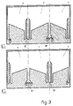
- FIG. 3 shows two contiguous stages E'1 and E'2 each with three juxtaposed modular chambers of the type described on the Figures 1 & 2, the three chambers 1 for E'1, the three chambers 1 for E'2, some having common mixing and training areas such as 20 & 21 and / or steam outlets municipalities such as 22 & 23.
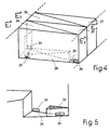
- FIG. 4 shows the case of a installation in which each stage E''1, E''2, E''3, E''4 forming part of a non- fully represented has a ceiling, respectively 24, 25, 26, 27 and a floor, respectively 28 for E''1, the others not being visible in FIG. 4, in shape triangular.
- stage E''1 the liquid supply from the stage immediately next is through the orifice 29 and in steam from the immediately preceding stage by the orifice 30 shown in Figure 4 and Figure 5 as a detail of the training area of the second installation described in the previous figure, the steam 31 and liquid 32 outlets of the separation zone feeds the next floor and the floor respectively immediately preceding.
- FIG. 5 shows a type of distributor with holes 33 which can be installed in the mixing zone in this second example of installation to ensure both liquid guard acting as a siphon 34 to prevent the passage of steam and a mixture said vapor and liquid streams.
Landscapes
- Chemical & Material Sciences (AREA)
- Chemical Kinetics & Catalysis (AREA)
- Vaporization, Distillation, Condensation, Sublimation, And Cold Traps (AREA)
Description
Claims (6)
- Procédé pour le transfert de constituants avec transfert thermique entre au moins un courant de liquide et au moins un courant de vapeur circulant par étapes successives dans une série de n étages ayant un axe commun, la progression du liquide et de la vapeur s'effectuant en sens inverse d'un étage à l'autre,
caractérisé en ce que:l'axe commun est sensiblement horizontal,dans chaque étage de rang n, le liquide et la vapeur circulent à cocourant et transversalement à l'axe commun depuis au moins une zone d'entrainement dans laquelle du liquide provenant à travers un orifice (8, 16, 29) de l'étage de rang n+1 est introduit par aspiration, puis élevé par de la vapeur provenant de l'étage de rang n-1, le liquide et la vapeur étant ensuite séparés par gravité au cours d'une circulation sensiblement horizontale dans au moins une zone intermédiaire avant de s'écouler séparés dans au moins une zone de collecte, les zones d'entrainement et de collecte étant alternées d'un étage à l'autre de facon que le liquide et la vapeur séparés dans un étage de rang n alimentent directement en liquide, respectivement en vapeur, une zone d'entrainement de l'étage de rang n-1, respectivement n+1. - Installation pour la mise en oeuvre du procédé selon la revendication 1, caractérisée en ce qu'elle comporte en fonctionnement:une pluralité d'étages séparateurs d'axe commun disposés horizontalement côte á côte en étant séparés par des parois communes sensiblement verticales,chaque étage comprenant au moins un module dans lequel le liquide et la vapeur circulent à cocourant et transversalement à l'axe commun depuis une zone d'entrainement dans laquelle de la vapeur provenant d'un premier orifice (10,30) situé à une extremité latérale inférieure du module aspire à travers un siphon (9, 34) et élève du liquide provenant d'un second orifice (7, 29) adjacent jusqu'à une zone de collecte dans laquelle le liquide et la vapeur séparés s'écoulent par des troisième (15, 32), respectivement quatrième (18, 31) orifices adjacents situés à l'autre extrèmité latérale inférieure du module et séparés par un seuil (40), les zones d'entrainement et de collecte étant séparées par une zone intermédiaire dans laquelle le liquide et la vapeur sont séparés par gravité,la disposition des orifices étant alternée d'un module au module correspondant de l'étage adjacent de facon à ce que les dits premier (10, 30) et quatrième (18, 31) orifices, respectivement deuxième (7, 29) et troisième (15, 32) orifices soient confondus en un orifice commun (11, 19), respectivement (8, 16) percé dans la paroi commune séparant ledit module du module correspondant de l'étage adjacent.
- Installation selon la revendication 2 caractérisée en ce que chaque étage comporte une pluralité de modules juxtaposés latéralement de facon telle que les zones d'entrainement, respectivement de collecte de deux modules soient jointes au niveau de la jonction de ces modules.
- Installation selon la revendication 2 caractérisée en ce que chaque étage est constitué d'un module délimité par un plafond et un plancher de forme triangulaire, la zone d'entrainement de liquide par la vapeur étant située dans la partie la plus étroite et la zone de collecte dans la partie la plus large du module.
- Installation selon la revendication 2 caractérisée en ce que sont prévus des moyens de chauffage des parois latérales (2, 3) et des moyens de refroidissement du plafond de chaque étage.
- Installation selon l une des revendications précédente carctérisée en ce que l'axe commun est incliné de 0.5 à 10 degrés sur l'horizontale.
Applications Claiming Priority (3)
| Application Number | Priority Date | Filing Date | Title |
|---|---|---|---|
| FR9302205A FR2701858B1 (fr) | 1993-02-26 | 1993-02-26 | Procédé pour le transfert de constituants avec transfert thermique entre un courant de vapeur et un courant de liquide, installation séparatrice pour la mise en Óoeuvre de ce procédé et application à la distillation. |
| FR9302205 | 1993-02-26 | ||
| PCT/FR1994/000205 WO1994019080A1 (fr) | 1993-02-26 | 1994-02-25 | Procede pour le transfert de constituants avec transfert thermique entre un courant de liquide et un courant de vapeur, une installation separatrice pour la mise en ×uvre de ce procede et application a la distillation |
Publications (2)
| Publication Number | Publication Date |
|---|---|
| EP0637982A1 EP0637982A1 (fr) | 1995-02-15 |
| EP0637982B1 true EP0637982B1 (fr) | 1998-02-04 |
Family
ID=9444443
Family Applications (1)
| Application Number | Title | Priority Date | Filing Date |
|---|---|---|---|
| EP94908371A Expired - Lifetime EP0637982B1 (fr) | 1993-02-26 | 1994-02-25 | Procede pour le transfert de constituants avec transfert thermique entre un courant de liquide et un courant de vapeur, installation separatrice pour la mise en oeuvre du procede. |
Country Status (4)
| Country | Link |
|---|---|
| EP (1) | EP0637982B1 (fr) |
| DE (1) | DE69408382T2 (fr) |
| FR (1) | FR2701858B1 (fr) |
| WO (1) | WO1994019080A1 (fr) |
Family Cites Families (4)
| Publication number | Priority date | Publication date | Assignee | Title |
|---|---|---|---|---|
| NL117897C (fr) * | 1940-03-01 | |||
| NL141025C (fr) * | 1946-11-26 | |||
| NL267837A (fr) * | 1961-01-02 | |||
| CH406143A (de) * | 1963-12-19 | 1966-01-31 | Sulzer Ag | Stoffaustauschkolonne |
-
1993
- 1993-02-26 FR FR9302205A patent/FR2701858B1/fr not_active Expired - Fee Related
-
1994
- 1994-02-25 DE DE69408382T patent/DE69408382T2/de not_active Expired - Fee Related
- 1994-02-25 WO PCT/FR1994/000205 patent/WO1994019080A1/fr not_active Ceased
- 1994-02-25 EP EP94908371A patent/EP0637982B1/fr not_active Expired - Lifetime
Also Published As
| Publication number | Publication date |
|---|---|
| WO1994019080A1 (fr) | 1994-09-01 |
| DE69408382T2 (de) | 1998-10-29 |
| EP0637982A1 (fr) | 1995-02-15 |
| FR2701858A1 (fr) | 1994-09-02 |
| DE69408382D1 (de) | 1998-03-12 |
| FR2701858B1 (fr) | 1995-05-24 |
Similar Documents
| Publication | Publication Date | Title |
|---|---|---|
| EP0130122B1 (fr) | Dispositif pour vaporiser un liquide par échange de chaleur avec un deuxième fluide et installation de distillation d'air comprenant un tel dispositif | |
| US5632962A (en) | Process vessel | |
| FR2500760A1 (fr) | Separateur multiphases | |
| KR100492827B1 (ko) | 화학 공정 타워용 동반 감소 조립체 | |
| FR2684893A1 (fr) | Procede de distillation reactive catalytique et appareillage pour sa mise en óoeuvre. | |
| FR2534150A1 (fr) | Installation de desulfuration de gaz de fumee et procede pour l'exploitation de l'installation | |
| FR2594043A1 (fr) | Procede pour transformer un evaporateur a longs tubes verticaux en evaporateur a film tombant et cet evaporateur. | |
| EP0017517A2 (fr) | Dispositif à chenaux pour le mélange des flux secs et humides de réfrigérant atmosphérique mixte à flux d'air parallèles | |
| JPH04215803A (ja) | 処理すべき流体から凝縮液として処理された流体を得る 装置 | |
| US6325361B1 (en) | Method and device for bringing a gas and a liquid into contact with one another | |
| EP1179724B1 (fr) | Echangeur thermique à blocs échangeurs multiples à ligne d'alimentation en fluide à distribution uniforme, et vaporiseur-condenseur comportant un tel échangeur | |
| TWI392842B (zh) | 回流凝結器 | |
| JPH1015301A5 (fr) | ||
| FR2462655A1 (fr) | Distributeur collecteur de boues pour generateur nucleaire de vapeur | |
| US8235362B2 (en) | Fluid distribution to parallel flow vapor-liquid contacting trays | |
| US3487873A (en) | Multiple effect flash evaporator | |
| JP2006522681A (ja) | 物質移動カラムのための複合型液体コレクタ及びミキサ | |
| FI95315C (fi) | Lämmönvaihdinlaitteisto erityisesti hybridilämpöpumppuja varten, jotka toimivat ei-aseotrooppisilla työfluideilla | |
| KR20110110289A (ko) | 탈비말동반 장치 | |
| US3864214A (en) | Apparatus for the Plural Stage Distillation of Drinking Alcohol | |
| FR2940138A1 (fr) | Colonne de stripage et procede pour extraire un composant d'un milieu liquide | |
| CN1057210A (zh) | 对流塔两交换部间的气液分配器 | |
| EP0629140A1 (fr) | Appareillage de distillation a effets multiples | |
| EP0637982A1 (fr) | Procede pour le transfert de constituants avec transfert thermique entre un courant de liquide et un courant de vapeur, installation separatrice pour la mise en oeuvre du procede. | |
| US4137173A (en) | Trap for grease or other foreign matter dissolved or entrained in a liquid |
Legal Events
| Date | Code | Title | Description |
|---|---|---|---|
| PUAI | Public reference made under article 153(3) epc to a published international application that has entered the european phase |
Free format text: ORIGINAL CODE: 0009012 |
|
| AK | Designated contracting states |
Kind code of ref document: A1 Designated state(s): DE DK GB NL SE |
|
| 17P | Request for examination filed |
Effective date: 19950222 |
|
| 17Q | First examination report despatched |
Effective date: 19960123 |
|
| GRAG | Despatch of communication of intention to grant |
Free format text: ORIGINAL CODE: EPIDOS AGRA |
|
| GRAG | Despatch of communication of intention to grant |
Free format text: ORIGINAL CODE: EPIDOS AGRA |
|
| GRAH | Despatch of communication of intention to grant a patent |
Free format text: ORIGINAL CODE: EPIDOS IGRA |
|
| RAP1 | Party data changed (applicant data changed or rights of an application transferred) |
Owner name: ORIEUX, ADRIEN |
|
| GRAH | Despatch of communication of intention to grant a patent |
Free format text: ORIGINAL CODE: EPIDOS IGRA |
|
| GRAA | (expected) grant |
Free format text: ORIGINAL CODE: 0009210 |
|
| AK | Designated contracting states |
Kind code of ref document: B1 Designated state(s): DE DK GB NL SE |
|
| PG25 | Lapsed in a contracting state [announced via postgrant information from national office to epo] |
Ref country code: NL Free format text: LAPSE BECAUSE OF FAILURE TO SUBMIT A TRANSLATION OF THE DESCRIPTION OR TO PAY THE FEE WITHIN THE PRESCRIBED TIME-LIMIT Effective date: 19980204 |
|
| PG25 | Lapsed in a contracting state [announced via postgrant information from national office to epo] |
Ref country code: SE Free format text: LAPSE BECAUSE OF NON-PAYMENT OF DUE FEES Effective date: 19980226 |
|
| REF | Corresponds to: |
Ref document number: 69408382 Country of ref document: DE Date of ref document: 19980312 |
|
| PGFP | Annual fee paid to national office [announced via postgrant information from national office to epo] |
Ref country code: NL Payment date: 19980424 Year of fee payment: 5 |
|
| PGFP | Annual fee paid to national office [announced via postgrant information from national office to epo] |
Ref country code: SE Payment date: 19980429 Year of fee payment: 5 |
|
| PG25 | Lapsed in a contracting state [announced via postgrant information from national office to epo] |
Ref country code: DK Free format text: LAPSE BECAUSE OF FAILURE TO SUBMIT A TRANSLATION OF THE DESCRIPTION OR TO PAY THE FEE WITHIN THE PRESCRIBED TIME-LIMIT Effective date: 19980504 |
|
| GBT | Gb: translation of ep patent filed (gb section 77(6)(a)/1977) |
Effective date: 19980512 |
|
| NLV1 | Nl: lapsed or annulled due to failure to fulfill the requirements of art. 29p and 29m of the patents act | ||
| PLBE | No opposition filed within time limit |
Free format text: ORIGINAL CODE: 0009261 |
|
| STAA | Information on the status of an ep patent application or granted ep patent |
Free format text: STATUS: NO OPPOSITION FILED WITHIN TIME LIMIT |
|
| EUG | Se: european patent has lapsed |
Ref document number: 94908371.1 |
|
| 26N | No opposition filed | ||
| PGFP | Annual fee paid to national office [announced via postgrant information from national office to epo] |
Ref country code: GB Payment date: 19990222 Year of fee payment: 6 |
|
| PG25 | Lapsed in a contracting state [announced via postgrant information from national office to epo] |
Ref country code: GB Free format text: LAPSE BECAUSE OF NON-PAYMENT OF DUE FEES Effective date: 20000225 |
|
| GBPC | Gb: european patent ceased through non-payment of renewal fee |
Effective date: 20000225 |
|
| REG | Reference to a national code |
Ref country code: GB Ref legal event code: 728V |
|
| REG | Reference to a national code |
Ref country code: GB Ref legal event code: 7281 |
|
| PGFP | Annual fee paid to national office [announced via postgrant information from national office to epo] |
Ref country code: DE Payment date: 20030430 Year of fee payment: 10 |
|
| PG25 | Lapsed in a contracting state [announced via postgrant information from national office to epo] |
Ref country code: DE Free format text: LAPSE BECAUSE OF NON-PAYMENT OF DUE FEES Effective date: 20040901 |