EP0637726B1 - Apparatus for cooling gases and optionally for drying particulate solids contained in the gas - Google Patents
Apparatus for cooling gases and optionally for drying particulate solids contained in the gas Download PDFInfo
- Publication number
- EP0637726B1 EP0637726B1 EP94111533A EP94111533A EP0637726B1 EP 0637726 B1 EP0637726 B1 EP 0637726B1 EP 94111533 A EP94111533 A EP 94111533A EP 94111533 A EP94111533 A EP 94111533A EP 0637726 B1 EP0637726 B1 EP 0637726B1
- Authority
- EP
- European Patent Office
- Prior art keywords
- gas
- reactor housing
- liquid
- vortex
- solid particles
- Prior art date
- Legal status (The legal status is an assumption and is not a legal conclusion. Google has not performed a legal analysis and makes no representation as to the accuracy of the status listed.)
- Expired - Lifetime
Links
Images

Classifications
-
- F—MECHANICAL ENGINEERING; LIGHTING; HEATING; WEAPONS; BLASTING
- F26—DRYING
- F26B—DRYING SOLID MATERIALS OR OBJECTS BY REMOVING LIQUID THEREFROM
- F26B3/00—Drying solid materials or objects by processes involving the application of heat
- F26B3/02—Drying solid materials or objects by processes involving the application of heat by convection, i.e. heat being conveyed from a heat source to the materials or objects to be dried by a gas or vapour, e.g. air
- F26B3/10—Drying solid materials or objects by processes involving the application of heat by convection, i.e. heat being conveyed from a heat source to the materials or objects to be dried by a gas or vapour, e.g. air the gas or vapour carrying the materials or objects to be dried with it
- F26B3/12—Drying solid materials or objects by processes involving the application of heat by convection, i.e. heat being conveyed from a heat source to the materials or objects to be dried by a gas or vapour, e.g. air the gas or vapour carrying the materials or objects to be dried with it in the form of a spray, i.e. sprayed or dispersed emulsions or suspensions
-
- B—PERFORMING OPERATIONS; TRANSPORTING
- B01—PHYSICAL OR CHEMICAL PROCESSES OR APPARATUS IN GENERAL
- B01D—SEPARATION
- B01D1/00—Evaporating
- B01D1/16—Evaporating by spraying
- B01D1/18—Evaporating by spraying to obtain dry solids
-
- B—PERFORMING OPERATIONS; TRANSPORTING
- B01—PHYSICAL OR CHEMICAL PROCESSES OR APPARATUS IN GENERAL
- B01F—MIXING, e.g. DISSOLVING, EMULSIFYING OR DISPERSING
- B01F25/00—Flow mixers; Mixers for falling materials, e.g. solid particles
- B01F25/30—Injector mixers
- B01F25/31—Injector mixers in conduits or tubes through which the main component flows
- B01F25/313—Injector mixers in conduits or tubes through which the main component flows wherein additional components are introduced in the centre of the conduit
- B01F25/3131—Injector mixers in conduits or tubes through which the main component flows wherein additional components are introduced in the centre of the conduit with additional mixing means other than injector mixers, e.g. screens, baffles or rotating elements
-
- B—PERFORMING OPERATIONS; TRANSPORTING
- B01—PHYSICAL OR CHEMICAL PROCESSES OR APPARATUS IN GENERAL
- B01F—MIXING, e.g. DISSOLVING, EMULSIFYING OR DISPERSING
- B01F25/00—Flow mixers; Mixers for falling materials, e.g. solid particles
- B01F25/40—Static mixers
- B01F25/42—Static mixers in which the mixing is affected by moving the components jointly in changing directions, e.g. in tubes provided with baffles or obstructions
- B01F25/43—Mixing tubes, e.g. wherein the material is moved in a radial or partly reversed direction
- B01F25/431—Straight mixing tubes with baffles or obstructions that do not cause substantial pressure drop; Baffles therefor
- B01F25/4316—Straight mixing tubes with baffles or obstructions that do not cause substantial pressure drop; Baffles therefor the baffles being flat pieces of material, e.g. intermeshing, fixed to the wall or fixed on a central rod
- B01F25/43163—Straight mixing tubes with baffles or obstructions that do not cause substantial pressure drop; Baffles therefor the baffles being flat pieces of material, e.g. intermeshing, fixed to the wall or fixed on a central rod in the form of small flat plate-like elements
-
- F—MECHANICAL ENGINEERING; LIGHTING; HEATING; WEAPONS; BLASTING
- F28—HEAT EXCHANGE IN GENERAL
- F28C—HEAT-EXCHANGE APPARATUS, NOT PROVIDED FOR IN ANOTHER SUBCLASS, IN WHICH THE HEAT-EXCHANGE MEDIA COME INTO DIRECT CONTACT WITHOUT CHEMICAL INTERACTION
- F28C3/00—Other direct-contact heat-exchange apparatus
- F28C3/06—Other direct-contact heat-exchange apparatus the heat-exchange media being a liquid and a gas or vapour
- F28C3/08—Other direct-contact heat-exchange apparatus the heat-exchange media being a liquid and a gas or vapour with change of state, e.g. absorption, evaporation, condensation
Definitions
- the invention relates to a device for cooling gases and optionally drying solid particles added to the gas, in particular evaporative coolers and spray dryers.
- Such devices are known for example from DE-A-32 29 843. They comprise a vertically arranged reactor housing, to which the gas is fed in the vertical direction through at least one feed line designed as an impact diffuser and which is flowed through in the vertical direction, liquid and optionally solid particles being fed to the gas through at least one nozzle after its entry into the reactor housing. Evaporation of the liquid removes heat of evaporation from the gas so that it is cooled. If the liquid supplied also contains solid particles, these are dried when flowing through the reactor housing.
- the known devices of the type described above designed as evaporative coolers or spray dryers, have the disadvantage that the gas flow not only enters the reactor housing with a non-uniform velocity profile across the cross section of the feed line, but also depending on the feed line profile with the central axis of the reactor housing deviating flow direction. This results in streaks of liquid and temperature within the reactor housing, which lead to a larger construction volume and a lower efficiency of the device.
- solid particles are added to the known devices, in particular due to the lateral deflection of the gas flow, there is a risk of deposits on the side walls, which lead to the reactor housing having to be cleaned at relatively short intervals, which means more frequent downtimes of the device.
- a swirl is imposed on the flow by vanes arranged in an annular flow cross-section surrounding the injection, which swirl is incorrectly referred to as a vortex flow.
- This swirl flow increases the flow path, it does not cause intensive mixing between the gas and the solid particles injected with the aid of liquid.
- the swirl is generated by curved or inclined guide surfaces of the blades provided with leading edges running at right angles to the main flow direction, as is also the case with guide blades as are known from FR-A-1 163 735. A lifting of temperature and concentration streaks in the area of the gas supply is not possible with the known devices.
- the invention has for its object to provide a device of the type described above for cooling gases and possibly drying solid particles added to the gas, in which the disadvantages described above are avoided with the least possible construction costs in that the gas flow is independent of the course of the feed line is fed uniformly and parallel to the longitudinal center axis of the reactor housing, and which causes an intensive mixing between the gas and the liquid and possibly the solid particles over a short distance with low flow losses.
- the solution to this problem by the invention is characterized in connection with the feed line designed as an impact diffuser, in that at least one vortex installation surface producing a leading edge vortex system is arranged in the region of the impact diffuser (for the term "leading edge vortex system” see, for example, "Guide through fluid dynamics”; L. Prandtl , K. Oswatitsch, K. Wieghardt; Friedr. Vieweg + Sohn GmbH, Braunschweig; 7th edition; 1969; pages 375 and 376).
- the inventive design creates a uniform pressure field in a ring around the entry of the gas into the reactor housing, which prevents a lateral deflection of the gas flow and causes a central alignment of the gas flow to the longitudinal center line of the reactor housing, the vortex installation surfaces in the region of the impact diffuser for intensive use which produce a leading edge vortex system and fast, ie Ensure that gas and liquid and any solid particles are mixed over a short distance so that the cooling and drying effect is completed after a short distance. Since the installation surfaces each producing a leading edge vortex system operate with little loss and require only a small amount of construction, the further development according to the invention is not associated with greater investment costs.
- Existing devices for cooling gases and optionally for drying solid particles added to the gas can also be converted in accordance with the proposal of the invention.
- the advantage is achieved that, despite the non-uniform flow profile in the feed line, a stable and uniform and centric distribution of the gas, which may be loaded with solid particles, takes place over the entire flow cross-section of the reactor housing, with simultaneous action on the reactor walls with liquid and Solid particles is avoided.
- the improved efficiency of the device resulting from the proposal according to the invention at the same time enables the construction volume of the reactor housing to be reduced, so that the device can be manufactured more cheaply.
- the maintenance effort is reduced by eliminating the periodically necessary cleaning.
- the downtimes that previously occurred due to the need for periodic cleaning are eliminated.
- the vortex installation surfaces can be arranged not only in the area of the shock diffuser, but also in the flow direction behind the shock diffuser in the reactor housing.
- the nozzles for supplying liquid and possibly solid particles are in the range of action of the Vortex built-in surfaces arranged, whereby the admixture of the liquid or the solid particles in the gas stream is optimized.
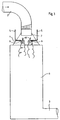
- the spray dryer shown schematically in FIG. 1 has a vertically arranged reactor housing 1, to which the gas to be cooled is fed from above through a feed line 2. At the lower end of the reactor housing 1, the cooled gas is discharged through an outlet 3.
- the horizontally arriving, subsequently arc-shaped supply line 2 which is connected centrally from above to the reactor housing 1, opens into a funnel-shaped housing attachment 4.
- liquid is supplied to the gas stream to be cooled, which through its Evaporation causes the gas to cool.
- liquid nozzles 6 are shown schematically. Solid particles can be introduced into this liquid flow.
- This impact diffuser 7 creates a uniform pressure field in a ring around the entry of the gas into the reactor housing 1, which despite the uneven speed profile of the entering gas flow prevents lateral deflection of the gas flow and causes a central alignment of the gas flow with the longitudinal center line of the reactor housing 1.
- vortex installation surfaces 8 arranged with their surface at an acute angle to the main flow direction of the gas result in only a negligibly small reduction in the flow cross section, so that the flow losses resulting from their installation are small. In addition, such vortex installation surfaces 8 require only little construction effort.
- FIG. 4 shows a triangular vortex installation surface 8, which is arranged with its tip opposite to the main flow direction.
- the vortex installation surface 8 shown in FIG. 5 is diamond-shaped and is likewise arranged with one of its tips opposite to the direction of flow and at an acute angle to the main direction of flow in the region of the impact diffuser 7.
- 6 and 7 show the basic shape of circular or oval vortex installation surfaces 8.
- These vortex installation surfaces 8 are also arranged at an acute angle to the main direction of flow in the gas flow and, by virtue of their leading edge flowing against them, result in the formation of leading edge vortex systems.
- a stabilization of the vortex installation surfaces 8 is also achieved in that they are provided with an angled edge.
- Fig. 1 further shows that a conversion of existing spray dryer is easily possible by installing a shock diffuser 7 and vortex mounting surfaces 8 in the housing attachment 4.
- the second exemplary embodiment according to FIGS. 2 and 3 shows that it is also possible to design the impact diffuser 7 by appropriately designing the transition between the feed line 2 and the reactor housing 1.
- the rectangular transition shown in FIG. 2 between the feed line 2 and the top of the reactor housing 1 inevitably creates an impact diffuser 7, in the area of which the vortex installation surfaces 8 can be arranged.
- the cross section in FIG. 3 shows an arrangement possibility for a total of four such vortex installation surfaces 8 with a triangular basic shape.
Landscapes
- Chemical & Material Sciences (AREA)
- Engineering & Computer Science (AREA)
- Chemical Kinetics & Catalysis (AREA)
- Mechanical Engineering (AREA)
- General Engineering & Computer Science (AREA)
- Dispersion Chemistry (AREA)
- Life Sciences & Earth Sciences (AREA)
- Microbiology (AREA)
- Vaporization, Distillation, Condensation, Sublimation, And Cold Traps (AREA)
- Drying Of Solid Materials (AREA)
- Devices And Processes Conducted In The Presence Of Fluids And Solid Particles (AREA)
Abstract
Description
Die Erfindung betrifft eine Vorrichtung zum Kühlen von Gasen und gegebenenfalls Trocknen von dem Gas zugegebenen Feststoffteilchen, insbesondere Verdampfungskühler und Sprühtrockner.The invention relates to a device for cooling gases and optionally drying solid particles added to the gas, in particular evaporative coolers and spray dryers.
Derartige Vorrichtungen sind beispielsweise aus DE-A-32 29 843 bekannt. Sie umfassen ein senkrecht angeordnetes Reaktorgehäuse, dem das Gas in senkrechter Richtung durch mindestens eine als Stoßdiffusor ausgebildete Zuleitung zugeführt wird und das in senkrechter Richtung durchströmt wird, wobei dem Gas nach seinem Eintritt in das Reaktorgehäuse Flüssigkeit und gegebenenfalls Feststoffpartikel durch mindestens eine Düse zugeführt werden. Durch Verdampfen der Flüssigkeit wird dem Gas Verdunstungswärme entzogen, so daß dieses gekühlt wird. Sofern in der zugeführten Flüssigkeit zusätzlich Feststoffteilchen enthalten sind, werden diese beim Durchströmen des Reaktorgehäuses getrocknet.Such devices are known for example from DE-A-32 29 843. They comprise a vertically arranged reactor housing, to which the gas is fed in the vertical direction through at least one feed line designed as an impact diffuser and which is flowed through in the vertical direction, liquid and optionally solid particles being fed to the gas through at least one nozzle after its entry into the reactor housing. Evaporation of the liquid removes heat of evaporation from the gas so that it is cooled. If the liquid supplied also contains solid particles, these are dried when flowing through the reactor housing.
Die bekannten, als Verdampfungskühler oder Sprühtrockner ausgebildeten Vorrichtungen der voranstehend beschriebenen Art haben den Nachteil, daß der Gasstrom nicht nur mit über den Querschnitt der Zuleitung ungleichmäßigem Geschwindigkeitsprofil in das Reaktorgehäuse eintritt, sondern abhängig vom Zuleitungsverlauf auch mit von der Mittelachse des Reaktorgehäuses abweichender Strömungsrichtung. Hierdurch ergeben sich innerhalb des Reaktorgehäuses Flüssigkeits- und Temperatursträhnen, die zu einem größeren Bauvolumen und einem geringeren Wirkungsgrad der Vorrichtung führen. Bei der Zugabe von Feststoffteilchen besteht bei den bekannten Vorrichtungen insbesondere aufgrund der seitlichen Ablenkung das Gasstromes die Gefahr von Ablagerungen an den Seitenwänden, die dazu führen, daß das Reaktorgehäuse in verhältnismäßig kurzen Zeitabständen gereinigt werden muß, womit häufigere Stillstandszeiten der Vorrichtung verbunden sind.The known devices of the type described above, designed as evaporative coolers or spray dryers, have the disadvantage that the gas flow not only enters the reactor housing with a non-uniform velocity profile across the cross section of the feed line, but also depending on the feed line profile with the central axis of the reactor housing deviating flow direction. This results in streaks of liquid and temperature within the reactor housing, which lead to a larger construction volume and a lower efficiency of the device. When solid particles are added to the known devices, in particular due to the lateral deflection of the gas flow, there is a risk of deposits on the side walls, which lead to the reactor housing having to be cleaned at relatively short intervals, which means more frequent downtimes of the device.
Bei der aus der DE-A-32 29 843 bekannten Vorrichtung wird durch in einem ringförmigen, die Eindüsung umgebenden Strömungsquerschnitt angeordnete Flügel der Strömung ein Drall aufgezwungen, der fälschlicherweise als Wirbelströmung bezeichnet wird. Diese Drallströmung vergrößert zwar den Strömungsweg, bewirkt aber keine intensive Vermischung zwischen dem Gas und den mit Hilfe von Flüssigkeit eingedüsten Feststoffteilchen. Der Drall wird durch gekrümmte oder schräggestellte Leitflächen der mit rechtwinklig zur Hauptströmungsrichtung verlaufenden Vorderkanten versehenen Schaufeln erzeugt, wie dies ebenfalls bei Leitschaufeln der Fall ist, wie sie aus der FR-A-1 163 735 bekannt sind. Eine Aufhebung von Temperatur- und Konzentrationssträhnen im Bereich der Gaszuführung ist mit den bekannten Vorrichtungen nicht möglich.In the device known from DE-A-32 29 843, a swirl is imposed on the flow by vanes arranged in an annular flow cross-section surrounding the injection, which swirl is incorrectly referred to as a vortex flow. Although this swirl flow increases the flow path, it does not cause intensive mixing between the gas and the solid particles injected with the aid of liquid. The swirl is generated by curved or inclined guide surfaces of the blades provided with leading edges running at right angles to the main flow direction, as is also the case with guide blades as are known from FR-A-1 163 735. A lifting of temperature and concentration streaks in the area of the gas supply is not possible with the known devices.
Der Erfindung liegt die Aufgabe zugrunde, eine Vorrichtung der eingangs beschriebenen Art zum Kühlen von Gasen und gegebenenfalls Trocknen von dem Gas zugegebenen Feststoffteilchen zu schaffen, bei der mit möglichst geringem Bauaufwand die voranstehend beschriebenen Nachteile dadurch vermieden werden, daß der Gasstrom unabhängig vom Verlauf der Zuleitung gleichmäßig und parallel zur Längsmittelachse dem Reaktorgehäuse zugeführt wird, und die mit geringen Strömungsverlusten eine intensive Vermischung zwischen dem Gas und der Flüssigkeit und gegebenenfalls der Feststoffteilchen auf kurzer Wegstrecke bewirkt.The invention has for its object to provide a device of the type described above for cooling gases and possibly drying solid particles added to the gas, in which the disadvantages described above are avoided with the least possible construction costs in that the gas flow is independent of the course of the feed line is fed uniformly and parallel to the longitudinal center axis of the reactor housing, and which causes an intensive mixing between the gas and the liquid and possibly the solid particles over a short distance with low flow losses.
Die Lösung dieser Aufgabenstellung durch die Erfindung ist in Verbindung mit der als Stoßdiffusor ausgebildeten Zuleitung dadurch gekennzeichnet, daß im Bereich des Stoßdiffusors mindestens eine ein Vorderkantenwirbelsystem erzeugende Wirbeleinbaufläche angeordnet ist (zum Begriff "Vorderkantenwirbelsystem" siehe z.B. "Führer durch die Strömungslehre" ; L. Prandtl, K. Oswatitsch, K. Wieghardt ; Friedr. Vieweg + Sohn GmbH, Braunschweig ; 7. Auflage ; 1969 ; Seiten 375 und 376).The solution to this problem by the invention is characterized in connection with the feed line designed as an impact diffuser, in that at least one vortex installation surface producing a leading edge vortex system is arranged in the region of the impact diffuser (for the term "leading edge vortex system" see, for example, "Guide through fluid dynamics"; L. Prandtl , K. Oswatitsch, K. Wieghardt; Friedr. Vieweg + Sohn GmbH, Braunschweig; 7th edition; 1969; pages 375 and 376).
Durch die erfindungsgemäße Ausbildung entsteht ringförmig um den Eintritt des Gases in das Reaktorgehäuse ein gleichmäßiges Druckfeld, das eine seitliche Ablenkung des Gasstromes verhindert und eine zentrische Ausrichtung des Gasstromes zur Längsmittellinie des Reaktorgehäuses bewirkt, wobei die ein Vorderkantenwirbelsystem erzeugenden Wirbeleinbauflächen im Bereich des Stoßdiffusors für eine intensive und schnelle, d.h. auf kurzer Weglänge erfolgende Vermischung von Gas und Flüssigkeit und gegebenenfalls Feststoffteilchen sorgen, so daß der Kühl- und Trocknungseffekt bereits nach kurzer Strecke abgeschlossen ist. Da die jeweils ein Vorderkantenwirbelsystem erzeugenden Einbauflächen verlustarm arbeiten und nur einen geringen Bauaufwand erfordern, ist die erfindungsgemäße Weiterbildung nicht mit größeren Investitionskosten verbunden. Auch bestehende Vorrichtungen zum Kühlen von Gasen und gegebenenfalls zum Trocknen von dem Gas zugegebenen Feststoffteilchen können gemäß dem Vorschlag der Erfindung umgerüstet werden.The inventive design creates a uniform pressure field in a ring around the entry of the gas into the reactor housing, which prevents a lateral deflection of the gas flow and causes a central alignment of the gas flow to the longitudinal center line of the reactor housing, the vortex installation surfaces in the region of the impact diffuser for intensive use which produce a leading edge vortex system and fast, ie Ensure that gas and liquid and any solid particles are mixed over a short distance so that the cooling and drying effect is completed after a short distance. Since the installation surfaces each producing a leading edge vortex system operate with little loss and require only a small amount of construction, the further development according to the invention is not associated with greater investment costs. Existing devices for cooling gases and optionally for drying solid particles added to the gas can also be converted in accordance with the proposal of the invention.
Mit dieser erfindungsgemäßen Weiterbildung der bekannten Vorrichtung wird der Vorteil erreicht, daß trotz ungleichförmigem Strömungsprofil in der Zuleitung eine stabile und gleichmäßige sowie zentrische Verteilung des gegebenenfalls mit Feststoffteilchen beladenen Gases auf den gesamten Strömungsquerschnitt des Reaktorgehäuses erfolgt, wobei gleichzeitig eine Beaufschlagung der Reaktorwände mit Flüssigkeits- und Feststoffteilchen vermieden wird. Der sich durch den erfindungsgemäßen Vorschlag ergebende bessere Wirkungsgrad der Vorrichtung ermöglicht gleichzeitig, das Bauvolumen des Reaktorgehäuses zu verringern, so daß die Vorrichtung preiswerter hergestellt werden kann. Weiterhin wird der Wartungsaufwand durch Wegfall der bisher periodisch notwendigen Reinigung verringert. Schließlich entfallen die bisher wegen der Notwendigkeit der periodischen Reinigung auftretenden Stillstandszeiten.With this development of the known device according to the invention, the advantage is achieved that, despite the non-uniform flow profile in the feed line, a stable and uniform and centric distribution of the gas, which may be loaded with solid particles, takes place over the entire flow cross-section of the reactor housing, with simultaneous action on the reactor walls with liquid and Solid particles is avoided. The improved efficiency of the device resulting from the proposal according to the invention at the same time enables the construction volume of the reactor housing to be reduced, so that the device can be manufactured more cheaply. Furthermore, the maintenance effort is reduced by eliminating the periodically necessary cleaning. Finally, the downtimes that previously occurred due to the need for periodic cleaning are eliminated.
Die Wirbeleinbauflächen können nicht nur im Bereich des Stoßdiffusors, sondern zusätzlich auch in Strömungsrichtung hinter dem Stoßdiffusor im Reaktorgehäuse angeordnet sein.The vortex installation surfaces can be arranged not only in the area of the shock diffuser, but also in the flow direction behind the shock diffuser in the reactor housing.
Gemäß einer bevorzugten Ausführungsform der Erfindung werden die Düsen zur Zufuhr von Flüssigkeit und gegebenenfalls Feststoffteilchen im Wirkungsbereich der Wirbeleinbauflächen angeordnet, wodurch die Beimischung der Flüssigkeit bzw. der Feststoffteilchen in den Gasstrom optimiert wird.According to a preferred embodiment of the invention, the nozzles for supplying liquid and possibly solid particles are in the range of action of the Vortex built-in surfaces arranged, whereby the admixture of the liquid or the solid particles in the gas stream is optimized.
Auf der Zeichnung sind zwei Ausführungsbeispiele der erfindungsgemäßen Vorrichtung dargestellt, und zwar zeigen:
- Fig. 1
- einen schematischen senkrechten Längsschnitt durch ein erstes, als Sprühtrockner ausgebildetes Ausführungsbeispiel,
- Fig. 2
- einen der Fig. 1 entsprechenden Längsschnitt durch den oberen Teil eines zweiten, als Verdampfungskühler ausgebildeten Ausführungsbeispiels,
- Fig. 3
- einen Querschnitt gemäß der Schnittlinie III-III in Fig. 2,
- Fig. 4 bis 7
- vier verschiedene Ausführungsbeispiele für die Ausbildung der Wirbeleinbauflächen und
- Fig. 8 und 9
- Querschnitte durch derartige Wirbeleinbauflächen.
- Fig. 1
- 2 shows a schematic vertical longitudinal section through a first exemplary embodiment designed as a spray dryer,
- Fig. 2
- 1 shows a longitudinal section corresponding to FIG. 1 through the upper part of a second exemplary embodiment designed as an evaporative cooler,
- Fig. 3
- 3 shows a cross section along the section line III-III in FIG. 2,
- 4 to 7
- four different embodiments for the formation of the vortex installation surfaces and
- 8 and 9
- Cross sections through such vortex installation surfaces.
Der in Fig. 1 schematisch dargestellte Sprühtrockner hat ein senkrechtstehend angeordnetes Reaktorgehäuse 1, dem das zu kühlende Gas von oben her durch eine Zuleitung 2 zugeführt wird. Am unteren Ende des Reaktorgehäuses 1 wird das gekühlte Gas durch eine Ableitung 3 abgeführt.The spray dryer shown schematically in FIG. 1 has a vertically arranged reactor housing 1, to which the gas to be cooled is fed from above through a
Die waagerecht ankommende, anschließend bogenförmig verlaufende und mittig von oben an das Reaktorgehäuse 1 angeschlossene Zuleitung 2 mündet beim dargestellten Ausführungsbeispiel nach Fig. 1 in einem sich trichterförmig erweiternden Gehäuseaufsatz 4. Im Bereich dieses Gehäuseaufsatzes 4 wird dem zu kühlenden Gasstrom Flüssigkeit zugeführt, die durch ihre Verdunstung eine Kühlung des Gases bewirkt. In Fig. 1 sind mehrere, am Ende von Flüssigkeitsleitungen 5 angeordnete Flüssigkeitsdüsen 6 schematisch eingezeichnet. In diesen Flüssigkeitsstrom können Feststoffteilchen eingegeben sein.In the illustrated embodiment according to FIG. 1, the horizontally arriving, subsequently arc-
Durch den bogenförmigen Verlauf der Zuleitung 2 ergibt sich vor dem Eintreten des Gasstromes in das Reaktorgehäuse ein über den Querschnitt der Zuleitung 2 ungleichförmiges Geschwindigkeitsprofil, das in Fig. 1 eingezeichnet ist. Hierdurch würde sich nicht nur eine Abweichung der Strömungsrichtung des Gasstromes von der Mittelachse des Reaktorgehäuses 1 ergeben, sondern auch das Entstehen von Flüssigkeits- und Temperatursträhnen innerhalb des Reaktorgehäuses 1. Um dies zu vermeiden, ist die Mündung der Zuleitung 2 als Stoßdiffusor 7 ausgebildet. Beim Ausführungsbeispiel nach Fig. 1 erfolgt diese Ausbildung durch die Anordnung eines kreiszylindrischen Ringes, der in Verlängerung der Zuleitung 2 in den trichterförmigen Gehäuseaufsatz 4 hineinragt. Durch diesen Stoßdiffusor 7 entsteht ringförmig um den Eintritt des Gases in das Reaktorgehäuse 1 ein gleichmäßiges Druckfeld, das trotz des ungleichmäßigen Geschwindigkeitsprofils des eintretenden Gasstromes eine seitliche Ablenkung des Gasstromes verhindert und eine zentrische Ausrichtung des Gasstromes zur Längsmittellinie des Reaktorgehäuses 1 bewirkt.Due to the curved course of the
Um eine intensive und schnelle, d.h. auf kurzer Weglänge erfolgende Vermischung des in das Reaktorgehäuse 1 eintretenden Gases und der diesem Gas durch die Flüssigkeitsdüsen 6 zugegebenen Flüssigkeit und gegebenenfalls auch Feststoffteilchen zu erzielen, sind im Bereich des Stoßdiffusors 7 Wirbeleinbauflächen 8 angeordnet, die jeweils ein Vorderkantenwirbelsystem erzeugen. Bei diesem Vorderkantenwirbelsystem handelt es sich um einen statischen Wirbelnachlauf, der mit geringen Wirbelverlusten aufgrund der Strömungskomponenten quer zur Hauptströmungsrichtung eine intensive Durchmischung erzielt und hierdurch das Entstehen von Temperatur- und Geschwindigkeitssträhnen verhindert. Auf diese Weise ist der Kühl- und Trocknungseffekt der zugeführten Flüssigkeit und der dem Gasstrom zugegebenen Feststoffteilchen bereits nach kurzer Strecke abgeschlossen, wodurch die Bauhöhe des Reaktorgehäuses 1 verkürzt werden kann. Die mit ihrer Oberfläche im spitzen Winkel zur Hauptströmungsrichtung des Gases angeordneten Wirbeleinbauflächen 8 haben nur eine vernachlässigbar kleine Verringerung des Strömungsquerschnittes zur Folge, so daß die durch ihren Einbau entstehenden Strömungsverluste gering sind. Außerdem erfordern derartige Wirbeleinbauflächen 8 nur einen geringen Bauaufwand.In order to mix the gas entering the reactor housing 1 and the gas added to it through the
In den Fig. 4 bis 9 sind Ausführungsbeispiele derartiger Wirbeleinbauflächen dargestellt. Die Fig. 4 zeigt eine in der Grundform dreieckige Wirbeleinbaufläche 8, die mit ihrer Spitze entgegengesetzt zur Hauptströmungsrichtung angeordnet wird. Die in Fig. 5 dargestellte Wirbeleinbaufläche 8 ist rautenförmig ausgebildet und wird ebenfalls mit einer ihrer Spitzen entgegengesetzt zur Strömungsrichtung und unter einem spitzen Winkel zur Hauptströmungsrichtung angestellt im Bereich des Stoßdiffusors 7 angeordnet. Die Fig. 6 und 7 zeigen in der Grundform kreisförmige bzw. ovale Wirbeleinbauflächen 8. Auch diese Wirbeleinbauflächen 8 werden unter einem spitzen Winkel zur Hauptströmungsrichtung im Gasstrom angeordnet und bewirken durch ihre angeströmte Vorderkante das Entstehen von Vorderkantenwirbelsystemen.4 to 9 show exemplary embodiments of such vortex installation surfaces. Fig. 4 shows a triangular
Um die Intensität des Mischwirbelsystems weiterhin zu erhöhen und die statische Stabilität der im Gasstrom liegenden Wirbeleinbauflächen 8 zu verbessern, können diese gemäß Fig. 8 profiliert, beispielsweise im Querschnitt V-förmig ausgebildet sein. Gemäß Fig. 9 wird eine Stabilisierung der Wirbeleinbauflächen 8 auch dadurch erreicht, daß sie mit einem abgewinkelten Rand versehen werden.In order to further increase the intensity of the mixed vortex system and to improve the static stability of the
Um eine schnelle Zumischung der Flüssigkeit in den Gasstrom zu bewirken, sind die Flüssigkeitsdüsen 6 im Wirkungsbereich der Wirbeleinbauflächen 8 angeordnet, wie dies in Fig. 1 erkennbar ist. Die Fig. 1 zeigt weiterhin, daß ein Umbau vorhandener Sprühtrockner ohne weiteres möglich ist, indem in den Gehäuseaufsatz 4 ein Stoßdiffusor 7 und Wirbeleinbauflächen 8 eingebaut werden.In order to bring about a rapid admixture of the liquid into the gas flow, the
Das zweite Ausführungsbeispiel nach den Fig. 2 und 3 zeigt, daß eine Ausbildung des Stoßdiffusors 7 auch durch entsprechende Ausbildung des Überganges zwischen der Zuleitung 2 und dem Reaktorgehäuse 1 möglich ist. Durch den in Fig. 2 gezeichneten rechtwinkligen Übergang zwischen Zuleitung 2 und Oberseite des Reaktorgehäuses 1 entsteht zwangsläufig ein Stoßdiffusor 7, in dessen Bereich die Wirbeleinbauflächen 8 angeordnet werden können. Der Querschnitt in Fig. 3 zeigt eine Anordnungsmöglichkeit für insgesamt vier derartige Wirbeleinbauflächen 8 mit dreieckförmiger Grundform.The second exemplary embodiment according to FIGS. 2 and 3 shows that it is also possible to design the
Beim zweiten Ausführungsbeispiel nach Fig. 2 sind in Strömungsrichtung hinter dem Stoßdiffusor 7 weitere Wirbeleinbauflächen 9 angeordnet, die durch ihre Vorderkantenwirbelsysteme den Mischeffekt verbessern und die Mischstrecke weiter verkürzen.In the second embodiment according to FIG. 2, further vortex installation surfaces 9 are arranged in the flow direction behind the
- 11
- ReaktorgehäuseReactor housing
- 22nd
- ZuleitungSupply
- 33rd
- Leitungmanagement
- 44th
- GehäuseaufsatzHousing attachment
- 55
- FlüssigkeitsleitungLiquid line
- 66
- FlüssigkeitsdüseLiquid nozzle
- 77
- StoßdiffusorShock diffuser
- 88th
- WirbeleinbauflächeVortex installation area
- 99
- WirbeleinbauflächeVortex installation area
Claims (3)
- Device for the cooling of gases and, in a given case, drying of solid substance particles added to the gas, in particular evaporation cooler and spray drier, with a vertically arranged reactor housing (1), to which the gas is fed in vertical direction through at least one feed duct (2) constructed as collision diffuser (7) and which is flowed through in vertical direction, wherein liquid and, in a given case, solid substance particles are fed through at least one nozzle (6) to the gas after its entry into the reactor housing (1), characterised thereby, that at least one whirl baffle (8) producing a front edge turbulence system is arranged in the region of the collision diffuser (7).
- Device according to claim 1, characterised thereby, that whirl baffles (9) are additionally arranged in the reactor housing (1) in flow direction behind the collision diffuser (7).
- Device according to claim 1 or 2, characterised thereby, that the nozzles (6) for the feed of liquid and, in a given case, solid substance particles are each arranged in the range of action of a whirl baffle (8).
Applications Claiming Priority (2)
| Application Number | Priority Date | Filing Date | Title |
|---|---|---|---|
| DE4325968 | 1993-08-03 | ||
| DE4325968A DE4325968C2 (en) | 1993-08-03 | 1993-08-03 | Device for cooling gases and optionally drying solid particles added to the gas |
Publications (2)
| Publication Number | Publication Date |
|---|---|
| EP0637726A1 EP0637726A1 (en) | 1995-02-08 |
| EP0637726B1 true EP0637726B1 (en) | 1997-06-18 |
Family
ID=6494319
Family Applications (1)
| Application Number | Title | Priority Date | Filing Date |
|---|---|---|---|
| EP94111533A Expired - Lifetime EP0637726B1 (en) | 1993-08-03 | 1994-07-23 | Apparatus for cooling gases and optionally for drying particulate solids contained in the gas |
Country Status (8)
| Country | Link |
|---|---|
| US (1) | US5547540A (en) |
| EP (1) | EP0637726B1 (en) |
| JP (1) | JPH07167562A (en) |
| AT (1) | ATE154691T1 (en) |
| DE (2) | DE4325968C2 (en) |
| DK (1) | DK0637726T3 (en) |
| ES (1) | ES2102737T3 (en) |
| GR (1) | GR3023909T3 (en) |
Cited By (3)
| Publication number | Priority date | Publication date | Assignee | Title |
|---|---|---|---|---|
| DE19820992A1 (en) * | 1998-05-11 | 1999-11-18 | Babcock Anlagen Gmbh | Device for mixing a gas stream flowing through a channel |
| DE102006004068A1 (en) * | 2006-01-28 | 2007-08-09 | Fisia Babcock Environment Gmbh | Method and device for mixing a fluid with a large gas flow rate |
| DE102006004069A1 (en) * | 2006-01-28 | 2007-09-06 | Fisia Babcock Environment Gmbh | Method and device for mixing a fluid with a large gas flow rate |
Families Citing this family (25)
| Publication number | Priority date | Publication date | Assignee | Title |
|---|---|---|---|---|
| PT762837E (en) * | 1995-03-31 | 2002-07-31 | Schur Jorg Peter | PROCESS FOR IMPROVING THE DURABILITY AND / OR STABILIZATION OF MICROBIOLOGICALLY DEGRADABLE PRODUCTS |
| DE19931185A1 (en) | 1999-07-07 | 2001-01-18 | Joerg Peter Schuer | Air disinfection process |
| DE19940283A1 (en) * | 1999-08-25 | 2001-03-01 | Joerg Peter Schuer | plant protection |
| DE19940605A1 (en) | 1999-08-27 | 2001-03-01 | Joerg Peter Schuer | impregnation process |
| US6322054B1 (en) * | 2000-03-17 | 2001-11-27 | Chung-Hsing Wu | Sprinkling apparatus for cooling tower |
| ATE235311T1 (en) * | 2000-06-19 | 2003-04-15 | Balcke Duerr Energietech Gmbh | MIXER FOR MIXING AT LEAST TWO GAS STREAMS OR OTHER NEWTONIAN LIQUIDS |
| DE20100121U1 (en) * | 2001-01-05 | 2002-05-16 | Schür, Jörg Peter, Prof., 41844 Wegberg | Device for enriching air with air treatment agent |
| DE10100595A1 (en) * | 2001-01-09 | 2002-07-18 | Joerg Peter Schuer | Process for non-toxic odor neutralization of air |
| US20030031588A1 (en) * | 2001-06-13 | 2003-02-13 | Schur Jorg Peter | Device for enriching air with an air treatment agent, especially for the disinfection of air, and/or perfuming of air and/or for odor masking |
| DE10129367A1 (en) * | 2001-06-20 | 2003-01-09 | Klingenburg Gmbh | The air humidification |
| WO2004051165A2 (en) * | 2002-12-03 | 2004-06-17 | Lg Electronics Inc. | Flow spreading mechanism |
| KR20050076213A (en) * | 2004-01-20 | 2005-07-26 | 삼성전자주식회사 | Clothing dryer |
| DK1568410T3 (en) | 2004-02-27 | 2010-06-14 | Haldor Topsoe As | Apparatus for mixing fluid streams |
| US7448794B2 (en) * | 2004-02-27 | 2008-11-11 | Haldor Topsoe A/S | Method for mixing fluid streams |
| US9295953B2 (en) * | 2004-10-01 | 2016-03-29 | Harald Linga | Multi fluid injection mixer |
| DE102004052827B4 (en) * | 2004-11-02 | 2010-05-06 | Lurgi Gmbh | Apparatus for producing an o-xylene-air mixture for phthalic anhydride production |
| ES2285577T3 (en) * | 2005-01-17 | 2007-11-16 | Balcke-Durr Gmbh | DEVICE AND PROCEDURE FOR MIXING A FLUID CIRCULATING IN A CIRCULATION DIRECTION. |
| DE102005059971A1 (en) * | 2005-12-15 | 2007-06-21 | Fisia Babcock Environment Gmbh | Smoke gases at high flow-rates are treated, to destroy nitrogen oxides, by injection of liquid reducing agents with high efficiency dispersal by vortex shedding from an inclined planar baffle |
| US8010236B2 (en) * | 2007-10-30 | 2011-08-30 | Babcock Power Environmental Inc. | Adaptive control system for reagent distribution control in SCR reactors |
| CN106123559A (en) * | 2016-07-14 | 2016-11-16 | 滨海金地矿业工程技术(北京)有限公司 | The most quickly temperature regulating device and the coal drying system of a kind of coal drying system |
| US20200078757A1 (en) | 2018-09-07 | 2020-03-12 | The Procter & Gamble Company | Methods and Systems for Forming Microcapsules |
| US20200078759A1 (en) | 2018-09-07 | 2020-03-12 | The Procter & Gamble Company | Methods and Systems for Forming Microcapsules |
| US20200078758A1 (en) | 2018-09-07 | 2020-03-12 | The Procter & Gamble Company | Methods and Systems for Forming Microcapsules |
| US11833481B2 (en) | 2018-10-05 | 2023-12-05 | Produced Water Absorbents Inc. | Multi-channel, variable-flow mixers and related methods |
| US11673104B2 (en) | 2018-12-07 | 2023-06-13 | Produced Water Absorbents Inc. | Multi-fluid injection mixer and related methods |
Family Cites Families (9)
| Publication number | Priority date | Publication date | Assignee | Title |
|---|---|---|---|---|
| CH353609A (en) * | 1956-12-04 | 1961-04-15 | Afico Sa | Process for manufacturing a soluble powdered extract of a plant material and installation for its implementation |
| US4187617A (en) * | 1978-12-18 | 1980-02-12 | Becker James J Jr | Spray dryer |
| US4380491A (en) * | 1981-08-26 | 1983-04-19 | Combustion Engineering, Inc. | Spray nozzle assembly for spray dryer |
| US4571311A (en) * | 1985-01-22 | 1986-02-18 | Combustion Engineering, Inc. | Apparatus for introducing a process gas into a treatment chamber |
| FR2583652B1 (en) * | 1985-06-21 | 1989-10-27 | Air Ind Environnement | IMPROVEMENT IN DUST-LOADED GAS COOLING TOWERS |
| US5232550A (en) * | 1987-04-27 | 1993-08-03 | Ohkawara Kakohki Co., Ltd. | Vacuum drying method |
| ATE68986T1 (en) * | 1987-07-03 | 1991-11-15 | Ciba Geigy Ag | SPRAY DRYERS FOR THE PRODUCTION OF POWDERS, AGGLOMERATES OR THE LIKE. |
| US5227017A (en) * | 1988-01-29 | 1993-07-13 | Ohkawara Kakohki Co., Ltd. | Spray drying apparatus equipped with a spray nozzle unit |
| DE4112750A1 (en) * | 1991-04-19 | 1992-10-22 | Balcke Duerr Ag | METHOD AND DEVICE FOR INCREASING THE SEPARATION PERFORMANCE OF SMOKE GAS DESULFURATION PLANTS |
-
1993
- 1993-08-03 DE DE4325968A patent/DE4325968C2/en not_active Expired - Fee Related
-
1994
- 1994-07-23 DE DE59403162T patent/DE59403162D1/en not_active Expired - Lifetime
- 1994-07-23 ES ES94111533T patent/ES2102737T3/en not_active Expired - Lifetime
- 1994-07-23 DK DK94111533.9T patent/DK0637726T3/en active
- 1994-07-23 EP EP94111533A patent/EP0637726B1/en not_active Expired - Lifetime
- 1994-07-23 AT AT94111533T patent/ATE154691T1/en active
- 1994-08-02 JP JP6210335A patent/JPH07167562A/en active Pending
- 1994-08-03 US US08/286,487 patent/US5547540A/en not_active Expired - Lifetime
-
1997
- 1997-06-26 GR GR970401557T patent/GR3023909T3/en unknown
Non-Patent Citations (1)
| Title |
|---|
| "Führer durch die Strömungslehre"; Prandtl, Oswatitsch, Wieghardt; Fried. Vieweg + Sohn GmbH, Braunschweig; 7. Auflage, 1969. * |
Cited By (4)
| Publication number | Priority date | Publication date | Assignee | Title |
|---|---|---|---|---|
| DE19820992A1 (en) * | 1998-05-11 | 1999-11-18 | Babcock Anlagen Gmbh | Device for mixing a gas stream flowing through a channel |
| DE19820992C2 (en) * | 1998-05-11 | 2003-01-09 | Bbp Environment Gmbh | Device for mixing a gas stream flowing through a channel and method using the device |
| DE102006004068A1 (en) * | 2006-01-28 | 2007-08-09 | Fisia Babcock Environment Gmbh | Method and device for mixing a fluid with a large gas flow rate |
| DE102006004069A1 (en) * | 2006-01-28 | 2007-09-06 | Fisia Babcock Environment Gmbh | Method and device for mixing a fluid with a large gas flow rate |
Also Published As
| Publication number | Publication date |
|---|---|
| DK0637726T3 (en) | 1998-01-26 |
| US5547540A (en) | 1996-08-20 |
| GR3023909T3 (en) | 1997-09-30 |
| ES2102737T3 (en) | 1997-08-01 |
| ATE154691T1 (en) | 1997-07-15 |
| DE4325968A1 (en) | 1995-02-09 |
| DE59403162D1 (en) | 1997-07-24 |
| JPH07167562A (en) | 1995-07-04 |
| EP0637726A1 (en) | 1995-02-08 |
| DE4325968C2 (en) | 1997-04-10 |
Similar Documents
| Publication | Publication Date | Title |
|---|---|---|
| EP0637726B1 (en) | Apparatus for cooling gases and optionally for drying particulate solids contained in the gas | |
| EP0433790B1 (en) | Burner | |
| DE69629276T2 (en) | FLAT NOZZLE | |
| DE10304386B4 (en) | Double fluid swirl nozzle with self-cleaning spigot | |
| DE19820992C2 (en) | Device for mixing a gas stream flowing through a channel and method using the device | |
| DE3728557C2 (en) | ||
| DE3131070A1 (en) | "SPRAY NOZZLE WITH HIGH EFFICIENCY" | |
| DE3419423A1 (en) | Spray nozzle | |
| EP1981621B1 (en) | Method and device for mixing a gaseous fluid with a large gas flow, especially to introduce a reducing agent into a flue gas containing nitrogen oxides | |
| DE2356863C2 (en) | Liquid fuel burners | |
| DE2658323A1 (en) | DEVICE FOR COOLING THROUGH ATOMIZATION | |
| DE2417355A1 (en) | CENTRIFUGAL PRESSURE NOZZLE | |
| DE102022121551A1 (en) | Mixer, mixer assembly and mixing method | |
| EP0751820B1 (en) | Combined feed and mixing installation | |
| DE10334593B3 (en) | mixing system | |
| EP1962995B2 (en) | Apparatus for mixing a fluid with a large gas stream, especially for introducing a reducing agent into a flue gas comprising nitrogen oxides | |
| EP0742411A2 (en) | Air supply for a premix combustor | |
| DE3701946C2 (en) | ||
| DE2711726C2 (en) | Device for atomizing a liquid, in particular for the production of melamine and the production of urea granules | |
| EP0670986B1 (en) | Mixing device | |
| DE102016014966B4 (en) | Exhaust aftertreatment device for a motor vehicle | |
| EP3152420B1 (en) | Injection module and exhaust system having an injection module | |
| DE3688127T2 (en) | ATOMIZING DEVICE. | |
| DE8900464U1 (en) | Steam cooling system | |
| DE2149445A1 (en) | Guide device for burner |
Legal Events
| Date | Code | Title | Description |
|---|---|---|---|
| PUAI | Public reference made under article 153(3) epc to a published international application that has entered the european phase |
Free format text: ORIGINAL CODE: 0009012 |
|
| AK | Designated contracting states |
Kind code of ref document: A1 Designated state(s): AT BE CH DE DK ES FR GB GR IE IT LI LU NL PT SE |
|
| 17P | Request for examination filed |
Effective date: 19950114 |
|
| 17Q | First examination report despatched |
Effective date: 19960110 |
|
| GRAG | Despatch of communication of intention to grant |
Free format text: ORIGINAL CODE: EPIDOS AGRA |
|
| GRAH | Despatch of communication of intention to grant a patent |
Free format text: ORIGINAL CODE: EPIDOS IGRA |
|
| GRAH | Despatch of communication of intention to grant a patent |
Free format text: ORIGINAL CODE: EPIDOS IGRA |
|
| GRAA | (expected) grant |
Free format text: ORIGINAL CODE: 0009210 |
|
| RAP1 | Party data changed (applicant data changed or rights of an application transferred) |
Owner name: DEUTSCHE BABCOCK ANLAGEN GMBH |
|
| AK | Designated contracting states |
Kind code of ref document: B1 Designated state(s): AT BE CH DE DK ES FR GB GR IE IT LI LU NL PT SE |
|
| REF | Corresponds to: |
Ref document number: 154691 Country of ref document: AT Date of ref document: 19970715 Kind code of ref document: T |
|
| REG | Reference to a national code |
Ref country code: CH Ref legal event code: EP |
|
| GBT | Gb: translation of ep patent filed (gb section 77(6)(a)/1977) |
Effective date: 19970619 |
|
| ET | Fr: translation filed | ||
| REF | Corresponds to: |
Ref document number: 59403162 Country of ref document: DE Date of ref document: 19970724 |
|
| PG25 | Lapsed in a contracting state [announced via postgrant information from national office to epo] |
Ref country code: LU Free format text: LAPSE BECAUSE OF NON-PAYMENT OF DUE FEES Effective date: 19970731 |
|
| REG | Reference to a national code |
Ref country code: ES Ref legal event code: FG2A Ref document number: 2102737 Country of ref document: ES Kind code of ref document: T3 |
|
| REG | Reference to a national code |
Ref country code: GR Ref legal event code: FG4A Free format text: 3023909 |
|
| ITF | It: translation for a ep patent filed | ||
| PG25 | Lapsed in a contracting state [announced via postgrant information from national office to epo] |
Ref country code: SE Effective date: 19970918 Ref country code: PT Effective date: 19970918 |
|
| REG | Reference to a national code |
Ref country code: DK Ref legal event code: T3 |
|
| REG | Reference to a national code |
Ref country code: IE Ref legal event code: FD4D Ref document number: 74771 Country of ref document: IE |
|
| PLBE | No opposition filed within time limit |
Free format text: ORIGINAL CODE: 0009261 |
|
| STAA | Information on the status of an ep patent application or granted ep patent |
Free format text: STATUS: NO OPPOSITION FILED WITHIN TIME LIMIT |
|
| 26N | No opposition filed | ||
| PGFP | Annual fee paid to national office [announced via postgrant information from national office to epo] |
Ref country code: CH Payment date: 20000616 Year of fee payment: 7 |
|
| PGFP | Annual fee paid to national office [announced via postgrant information from national office to epo] |
Ref country code: NL Payment date: 20000620 Year of fee payment: 7 |
|
| PGFP | Annual fee paid to national office [announced via postgrant information from national office to epo] |
Ref country code: GR Payment date: 20000630 Year of fee payment: 7 |
|
| PGFP | Annual fee paid to national office [announced via postgrant information from national office to epo] |
Ref country code: BE Payment date: 20000704 Year of fee payment: 7 |
|
| PGFP | Annual fee paid to national office [announced via postgrant information from national office to epo] |
Ref country code: ES Payment date: 20000720 Year of fee payment: 7 |
|
| PGFP | Annual fee paid to national office [announced via postgrant information from national office to epo] |
Ref country code: GB Payment date: 20010614 Year of fee payment: 8 |
|
| PG25 | Lapsed in a contracting state [announced via postgrant information from national office to epo] |
Ref country code: ES Free format text: LAPSE BECAUSE OF NON-PAYMENT OF DUE FEES Effective date: 20010724 |
|
| PG25 | Lapsed in a contracting state [announced via postgrant information from national office to epo] |
Ref country code: LI Free format text: LAPSE BECAUSE OF NON-PAYMENT OF DUE FEES Effective date: 20010731 Ref country code: GR Free format text: LAPSE BECAUSE OF NON-PAYMENT OF DUE FEES Effective date: 20010731 Ref country code: CH Free format text: LAPSE BECAUSE OF NON-PAYMENT OF DUE FEES Effective date: 20010731 Ref country code: BE Free format text: LAPSE BECAUSE OF NON-PAYMENT OF DUE FEES Effective date: 20010731 |
|
| REG | Reference to a national code |
Ref country code: GB Ref legal event code: IF02 |
|
| BERE | Be: lapsed |
Owner name: DEUTSCHE BABCOCK ANLAGEN G.M.B.H. Effective date: 20010731 |
|
| PG25 | Lapsed in a contracting state [announced via postgrant information from national office to epo] |
Ref country code: NL Free format text: LAPSE BECAUSE OF NON-PAYMENT OF DUE FEES Effective date: 20020201 |
|
| REG | Reference to a national code |
Ref country code: CH Ref legal event code: PL |
|
| NLV4 | Nl: lapsed or anulled due to non-payment of the annual fee |
Effective date: 20020201 |
|
| PG25 | Lapsed in a contracting state [announced via postgrant information from national office to epo] |
Ref country code: GB Free format text: LAPSE BECAUSE OF NON-PAYMENT OF DUE FEES Effective date: 20020723 |
|
| GBPC | Gb: european patent ceased through non-payment of renewal fee |
Effective date: 20020723 |
|
| REG | Reference to a national code |
Ref country code: ES Ref legal event code: FD2A Effective date: 20020810 |
|
| REG | Reference to a national code |
Ref country code: FR Ref legal event code: TP Ref country code: FR Ref legal event code: CD Ref country code: FR Ref legal event code: CA |
|
| PGFP | Annual fee paid to national office [announced via postgrant information from national office to epo] |
Ref country code: DK Payment date: 20110720 Year of fee payment: 18 |
|
| PGFP | Annual fee paid to national office [announced via postgrant information from national office to epo] |
Ref country code: FR Payment date: 20120806 Year of fee payment: 19 Ref country code: DE Payment date: 20120713 Year of fee payment: 19 Ref country code: IT Payment date: 20120727 Year of fee payment: 19 |
|
| PGFP | Annual fee paid to national office [announced via postgrant information from national office to epo] |
Ref country code: AT Payment date: 20120711 Year of fee payment: 19 |
|
| REG | Reference to a national code |
Ref country code: DK Ref legal event code: EBP Effective date: 20130731 |
|
| REG | Reference to a national code |
Ref country code: AT Ref legal event code: MM01 Ref document number: 154691 Country of ref document: AT Kind code of ref document: T Effective date: 20130723 |
|
| REG | Reference to a national code |
Ref country code: FR Ref legal event code: ST Effective date: 20140331 |
|
| PG25 | Lapsed in a contracting state [announced via postgrant information from national office to epo] |
Ref country code: DE Free format text: LAPSE BECAUSE OF NON-PAYMENT OF DUE FEES Effective date: 20140201 |
|
| REG | Reference to a national code |
Ref country code: DE Ref legal event code: R119 Ref document number: 59403162 Country of ref document: DE Effective date: 20140201 |
|
| PG25 | Lapsed in a contracting state [announced via postgrant information from national office to epo] |
Ref country code: IT Free format text: LAPSE BECAUSE OF NON-PAYMENT OF DUE FEES Effective date: 20130723 Ref country code: AT Free format text: LAPSE BECAUSE OF NON-PAYMENT OF DUE FEES Effective date: 20130723 Ref country code: FR Free format text: LAPSE BECAUSE OF NON-PAYMENT OF DUE FEES Effective date: 20130731 |
|
| PG25 | Lapsed in a contracting state [announced via postgrant information from national office to epo] |
Ref country code: DK Free format text: LAPSE BECAUSE OF NON-PAYMENT OF DUE FEES Effective date: 20130731 |