EP0637109B1 - Doped fluoride glassfiber optical amplifier and method for its manufacture - Google Patents
Doped fluoride glassfiber optical amplifier and method for its manufacture Download PDFInfo
- Publication number
- EP0637109B1 EP0637109B1 EP94401706A EP94401706A EP0637109B1 EP 0637109 B1 EP0637109 B1 EP 0637109B1 EP 94401706 A EP94401706 A EP 94401706A EP 94401706 A EP94401706 A EP 94401706A EP 0637109 B1 EP0637109 B1 EP 0637109B1
- Authority
- EP
- European Patent Office
- Prior art keywords
- fibre
- optical
- silica
- fluoride glass
- doped
- Prior art date
- Legal status (The legal status is an assumption and is not a legal conclusion. Google has not performed a legal analysis and makes no representation as to the accuracy of the status listed.)
- Expired - Lifetime
Links
Images
Classifications
-
- H—ELECTRICITY
- H01—ELECTRIC ELEMENTS
- H01S—DEVICES USING THE PROCESS OF LIGHT AMPLIFICATION BY STIMULATED EMISSION OF RADIATION [LASER] TO AMPLIFY OR GENERATE LIGHT; DEVICES USING STIMULATED EMISSION OF ELECTROMAGNETIC RADIATION IN WAVE RANGES OTHER THAN OPTICAL
- H01S3/00—Lasers, i.e. devices using stimulated emission of electromagnetic radiation in the infrared, visible or ultraviolet wave range
- H01S3/05—Construction or shape of optical resonators; Accommodation of active medium therein; Shape of active medium
- H01S3/06—Construction or shape of active medium
- H01S3/063—Waveguide lasers, i.e. whereby the dimensions of the waveguide are of the order of the light wavelength
- H01S3/067—Fibre lasers
- H01S3/06754—Fibre amplifiers
-
- G—PHYSICS
- G02—OPTICS
- G02B—OPTICAL ELEMENTS, SYSTEMS OR APPARATUS
- G02B6/00—Light guides; Structural details of arrangements comprising light guides and other optical elements, e.g. couplings
- G02B6/24—Coupling light guides
- G02B6/26—Optical coupling means
- G02B6/28—Optical coupling means having data bus means, i.e. plural waveguides interconnected and providing an inherently bidirectional system by mixing and splitting signals
- G02B6/2804—Optical coupling means having data bus means, i.e. plural waveguides interconnected and providing an inherently bidirectional system by mixing and splitting signals forming multipart couplers without wavelength selective elements, e.g. "T" couplers, star couplers
-
- H—ELECTRICITY
- H01—ELECTRIC ELEMENTS
- H01S—DEVICES USING THE PROCESS OF LIGHT AMPLIFICATION BY STIMULATED EMISSION OF RADIATION [LASER] TO AMPLIFY OR GENERATE LIGHT; DEVICES USING STIMULATED EMISSION OF ELECTROMAGNETIC RADIATION IN WAVE RANGES OTHER THAN OPTICAL
- H01S3/00—Lasers, i.e. devices using stimulated emission of electromagnetic radiation in the infrared, visible or ultraviolet wave range
- H01S3/14—Lasers, i.e. devices using stimulated emission of electromagnetic radiation in the infrared, visible or ultraviolet wave range characterised by the material used as the active medium
- H01S3/16—Solid materials
- H01S3/17—Solid materials amorphous, e.g. glass
- H01S3/173—Solid materials amorphous, e.g. glass fluoride glass, e.g. fluorozirconate or ZBLAN [ ZrF4-BaF2-LaF3-AlF3-NaF]
Definitions
- the present invention relates to an optical fiber optic amplifier made of doped fluorinated glass and a method of manufacturing this amplifier.
- optical fiber amplifiers doped with a rare earth can be used to make telecommunications systems, both in transmission and in distribution.
- Erbium-doped silica fiber optical amplifier has been the most studied.
- Fluorinated glass fibers are now commercially available and it has been shown that doping the core of such fibers with erbium (respectively praseodymium) makes it possible to amplify radiation whose wavelength is close to 1.5 ⁇ m (respectively 1.3 ⁇ m).
- This property is interesting for transmitting a wavelength multiplex and several methods have been proposed for "flattening" the gain spectrum of amplifiers produced using doped silica fibers.
- fluorinated glass fibers doped with erbium is the simplest solution for producing optical amplifiers with flat spectral gain.
- the only fiber optic amplifier that can function properly at present is a fiber amplifier made of fluoride glass doped with praseodymium.
- these amplifiers based on fluorinated glass fibers must be inserted between two ends of optical fibers in silica and it is important that the input and the output of these amplifiers are wired in standard optical fibers of silica ( CCITT recommendation G652).
- a known solution consists in joining a fluorinated glass fiber and a standard silica fiber by means of a connector.
- a fluorinated glass fiber for example of the type of the OPTABALL system (registered trademark) marketed by the company Radial, whose dynamic losses can be adjusted.
- an optical amplifier comprising an optical fiber made of doped fluorinated glass, which is connected, on one side, to a silica fiber by means of such a connector (input connector) and, from the on the other hand, to another silica fiber by a connector of the same type (output connector).
- the reduction in the size of the optical mode in the doped fluorinated glass fiber causes intolerable losses when injecting the pumping radiation and the signal to be amplified, through the input connector, and upon extraction of the amplified signal, through the output connector of the doped fluorinated glass fiber.
- the adaptation of the optical mode diameter between the standard silica fiber and the doped fluorinated glass fiber can be improved by using an intermediate silica fiber having the same mode diameter as the doped fluorinated glass fiber, this intermediate fiber being welded by fusion with standard fiber on one side and bonded with fluorinated glass fiber doped on the other side.
- Fusion welding of the two silica fibers gives losses typically less than 0.3 dB while bonding of the silica fiber to the doped fluorinated glass fiber is carried out with losses typically less than 0.4 dB.
- the aim of the present invention is to remedy these drawbacks by proposing an optical amplifier with optical fiber made of doped fluorinated glass and a method of manufacturing this amplifier which make it possible both to minimize the coupling losses to the fiber made of doped fluorinated glass, to avoid the problems due to bonding which have been mentioned above and to have an input and an output of the optical amplifier made of standard silica optical fibers.
- optical fiber made of fluorinated glass doped so as to be able to amplify a light signal one understands an optical fiber whose core is made of fluorinated glass suitably doped to constitute an amplifying medium with respect to the signal .
- this fluorinated glass core is for example doped with erbium or praseodymium ions.
- the optical coupling means is another 2 to 1 type optical multiplexer which comprises, on the one hand, two optical fibers made of silica and, on the other hand , fluorinated glass fiber.
- An optical amplifier with a symmetrical structure is thus obtained, with inputs and outputs on silica fibers.
- the core of said optical fiber section can be doped with ions of at least one rare earth.
- the optical fiber made of fluorinated glass is doped over its entire length.
- the fluorinated glass optical fiber comprises a section of fluorinated glass optical fiber doped so as to be able to amplify the light signal and, on both sides of this section, two other sections of optical fiber made of undoped fluorinated glass.
- a standard silica optical fiber is welded to each of said silica optical fibers and another standard silica optical fiber to said other silica optical fiber, the diameter of mode of the fluorinated glass optical fiber being equal to the mode diameter of said silica optical fibers and of said other silica optical fiber and less than the mode diameter of standard silica fibers.
- the ends of the fluorinated glass fiber are polished perpendicular or oblique to its axis.
- the optical amplifier according to the invention is inserted into an optical line constituted by an optical fiber 16 of standard silica in which an optical signal S propagates.
- the optical fiber 16 is interrupted for the insertion of this optical amplifier.
- a part 16a of the fiber 16 is optically coupled to the optical fiber 6 of this amplifier by a fusion weld 18 and the other part 16b of this optical fiber 16 is optically coupled to the optical fiber 12 of the amplifier by a solder by merger 20.
- the optical amplifier of FIG. 1 is also fitted with a pumping laser 22 comprising an output optical fiber made of standard silica 24 and the latter is welded by fusion to the optical fiber 8 at point A.
- Fibers 2, 6, 8, 12 and 14 are single-mode and have the same mode diameter and the latter is less than the mode diameter of fibers 16 and 24 (also single-mode).
- the welds 18 and 20 and the welds at A and B are made so as to lead to losses of less than 0.3 dB.
- optical signal SA resulting from the amplification of the signal S by the amplifier of the FIG. 1, leaves the latter via fiber 12 to propagate in fiber 16.
- the optical pumping is co-directional (the pumping radiation P supplied by the laser 22 propagates in the same direction as the signal S).
- the residual pumping radiation R is transmitted by the optical fiber 14.
- the end of the output fiber placed in this multiplexer is polished perpendicular or oblique to its axis.
- the “silica-fluorinated glass” transition therefore takes place via the lenses of the multiplexer 4.
- the optical multiplexer 4 is manufactured with a single-mode output fiber 30 made of undoped fluorinated glass.
- the optical multiplexer 10 is manufactured with a single-mode optical fiber input 32 made of undoped fluorinated glass and the free ends of fibers 30 and 32 are welded by fusion respectively to the ends of a section of single mode optical fiber 28 made of fluorinated glass doped with a rare earth (the connection points carrying references B and C respectively in FIG. 2).
- the fibers 6, 8, 12, 14, 30 and 32 have the same mode diameter as the standard silica fibers 16 and 24 and that the fiber 28 has a mode diameter inferior.
- the optimal length of the amplifying fiber is determined.
- This determination is made by examining the amplified spontaneous emission using an optical spectrum analyzer.
- the multiplexer 10 (identical to the multiplexer 4) is mounted at the free end of the optical fiber 2, this fiber 2 thus entering the multiplexer 10.
- This fiber 2 which is in this multiplexer 10 is polished perpendicular or oblique to its optical axis.
- the optical amplifier according to the invention which is shown in Figure 1, has a symmetrical structure.
- the amplifier of FIG. 1 advantageously allows the filtering of the residual pumping radiation R at the output of this amplifier, thanks to the optical filter (not shown) that the multiplexer 10 includes.
- the structure of the amplifier shown in FIG. 1 also makes it possible to use contra-directional pumping as shown schematically in FIG. 3.
- a counter-directional pumping is then carried out and the residual pumping radiation R propagates in the optical fiber 8.
- the fibers 8 and 14 are respectively coupled to pumping lasers 40 and 38 to carry out both a co-directional pumping and a contra-directional pumping.
- the laser 40 comprises a standard output single-mode silica fiber 42 which is welded to the fiber 8 by fusion at point E.
- the multiplexer 10 is manufactured without an optical filter or an optical fiber 14, which amounts to simply manufacturing a fluorinated glass-silica transition.
Description
La présente invention concerne un amplificateur optique à fibre optique en verre fluoré dopé et un procédé de fabrication de cet amplificateur.The present invention relates to an optical fiber optic amplifier made of doped fluorinated glass and a method of manufacturing this amplifier.
Elle trouve notamment des applications dans le domaine des télécommunications par fibres optiques.It finds in particular applications in the field of telecommunications by optical fibers.
On sait qu'on peut utiliser des amplificateurs optiques à fibre dopée par une terre rare pour réaliser des systèmes de télécommunication, tant en transmission qu'en distribution.We know that optical fiber amplifiers doped with a rare earth can be used to make telecommunications systems, both in transmission and in distribution.
C'est l'amplificateur optique à fibre de silice dopée par l'erbium qui a été le plus étudié.Erbium-doped silica fiber optical amplifier has been the most studied.
Depuis peu, des études ont montré que d'autres verres que la silice pouvaient donner des fibres optiques de bonne qualité et que ces fibres pouvaient également être dopées par des terres rares.Recently, studies have shown that other glasses than silica can give good quality optical fibers and that these fibers can also be doped with rare earths.
Des fibres en verre fluoré, le ZBLAN par exemple, sont à présent commercialement disponibles et il a été démontré que le dopage du coeur de telles fibres par l'erbium (respectivement le praséodyme) permettait d'amplifier un rayonnement dont la longueur d'onde est voisine de 1,5 µm (respectivement 1,3 µm).Fluorinated glass fibers, ZBLAN for example, are now commercially available and it has been shown that doping the core of such fibers with erbium (respectively praseodymium) makes it possible to amplify radiation whose wavelength is close to 1.5 µm (respectively 1.3 µm).
Pour des longueurs d'onde voisines de 1,5 µm, de telles fibres dopées par l'erbium permettent de réaliser un amplificateur optique dont le gain, en fonction de la longueur d'onde, est quasiment constant de façon naturelle, ce qui n'est pas le cas pour un amplificateur à fibre de silice dopée par l'erbium.For wavelengths close to 1.5 µm, such erbium-doped fibers make it possible to produce an optical amplifier whose gain, as a function of the wavelength, is almost constant naturally, which doesn is not the case for an erbium-doped silica fiber amplifier.
Cette propriété est intéressante pour transmettre un multiplex de longueurs d'onde et plusieurs méthodes ont été proposées pour "aplatir" le spectre de gain des amplificateurs réalisés à l'aide de fibres de silice dopée.This property is interesting for transmitting a wavelength multiplex and several methods have been proposed for "flattening" the gain spectrum of amplifiers produced using doped silica fibers.
En fait, l'utilisation de fibres en verre fluoré dopé par l'erbium est la solution la plus simple pour réaliser des amplificateurs optiques à gain spectral plat.In fact, the use of fluorinated glass fibers doped with erbium is the simplest solution for producing optical amplifiers with flat spectral gain.
De plus, des résultats récents ont montré que des rendements de pompage équivalents aux rendements de pompage de la silice dopée par des ions Er3+ pouvaient être atteints avec de telles fibres en verre fluoré dopé par l'erbium.In addition, recent results have shown that pumping yields equivalent to the pumping yields of silica doped with Er 3+ ions can be achieved with such fibers of fluoride glass doped with erbium.
Pour des longueurs d'onde voisines de 1,3 µm, le seul amplificateur optique à fibre qui puisse convenablement fonctionner actuellement est un amplificateur à fibre en verre fluoré dopé par le praséodyme.For wavelengths in the region of 1.3 µm, the only fiber optic amplifier that can function properly at present is a fiber amplifier made of fluoride glass doped with praseodymium.
Dans les systèmes de télécommunication, ces amplificateurs à base de fibres en verre fluoré doivent s'insérer entre deux extrémités de fibres optiques en silice et il est important que l'entrée et la sortie de ces amplificateurs soient câblées en fibres optiques de silice standard (recommandation CCITT G652).In telecommunications systems, these amplifiers based on fluorinated glass fibers must be inserted between two ends of optical fibers in silica and it is important that the input and the output of these amplifiers are wired in standard optical fibers of silica ( CCITT recommendation G652).
Ceci pose le problème de la jonction des fibres de silice et des fibres en verre fluoré.This poses the problem of joining the silica fibers and the fluorinated glass fibers.
Il n'est pas possible de souder par fusion une fibre en verre fluoré (dopé ou non dopé) avec une fibre en silice, du fait que leurs températures de fusion sont très différentes l'une de l'autre.It is not possible to weld a fluorinated glass fiber (doped or undoped) with a silica fiber, because their melting temperatures are very different from each other.
En conséquence, il n'est pas possible d'utiliser les techniques de fabrication des amplificateurs optiques à base de silice pour réaliser un amplificateur optique à fibre en verre fluoré dopé.Consequently, it is not possible to use the techniques for manufacturing optical amplifiers based on silica to produce an optical amplifier made of doped fluorinated glass fiber.
Pour résoudre ce problème, une solution connue consiste à joindre une fibre en verre fluoré et une fibre de silice standard au moyen d'un connecteur par exemple du genre du système OPTABALL (marque déposée) commercialisé par la société Radial, dont on peut ajuster les pertes en dynamique.To solve this problem, a known solution consists in joining a fluorinated glass fiber and a standard silica fiber by means of a connector. for example of the type of the OPTABALL system (registered trademark) marketed by the company Radial, whose dynamic losses can be adjusted.
On peut ainsi réaliser un amplificateur optique comprenant une fibre optique en verre fluoré dopé, qui est reliée, d'un côté, à une fibre de silice par l'intermédiaire d'un tel connecteur (connecteur d'entrée) et, de l'autre côté, à une autre fibre de silice par un connecteur du même type (connecteur de sortie).It is thus possible to produce an optical amplifier comprising an optical fiber made of doped fluorinated glass, which is connected, on one side, to a silica fiber by means of such a connector (input connector) and, from the on the other hand, to another silica fiber by a connector of the same type (output connector).
Cependant, la diminution de la taille du mode optique dans la fibre en verre fluoré dopé, nécessaire pour avoir une efficacité de pompage aussi grande que possible, engendre des pertes intolérables à l'injection du rayonnement de pompage et du signal à amplifier, à travers le connecteur d'entrée, et à l'extraction du signal amplifié, à travers le connecteur de sortie de la fibre en verre fluoré dopé.However, the reduction in the size of the optical mode in the doped fluorinated glass fiber, necessary to have as high pumping efficiency as possible, causes intolerable losses when injecting the pumping radiation and the signal to be amplified, through the input connector, and upon extraction of the amplified signal, through the output connector of the doped fluorinated glass fiber.
L'adaptation du diamètre de mode optique entre la fibre en silice standard et la fibre en verre fluoré dopé peut être améliorée en utilisant une fibre de silice intermédiaire ayant le même diamètre de mode que la fibre en verre fluoré dopé, cette fibre intermédiaire étant soudée par fusion à la fibre standard d'un côté et collée à la fibre en verre fluoré dopé de l'autre côté.The adaptation of the optical mode diameter between the standard silica fiber and the doped fluorinated glass fiber can be improved by using an intermediate silica fiber having the same mode diameter as the doped fluorinated glass fiber, this intermediate fiber being welded by fusion with standard fiber on one side and bonded with fluorinated glass fiber doped on the other side.
IEEE Photonics Technology Letters, vol. 5, no. 4, Avril 1993, pages 401-403, décrit un amplificateur comprenant un multiplexeur en silice, une fibre intermédiaire en silice et une fibre en verre fluoré dopé qui est couplée par "butt-joint" à la fibre intermédiaire.IEEE Photonics Technology Letters, vol. 5, no. 4, April 1993, pages 401-403, describes an amplifier comprising a silica multiplexer, an intermediate silica fiber and a doped fluorinated glass fiber which is coupled by "butt-joint" to the intermediate fiber.
La soudure par fusion des deux fibres de silice donne des pertes typiquement inférieures à 0,3 dB tandis que le collage de la fibre de silice à la fibre en verre fluoré dopé s'effectue avec des pertes typiquement inférieures à 0,4 dB.Fusion welding of the two silica fibers gives losses typically less than 0.3 dB while bonding of the silica fiber to the doped fluorinated glass fiber is carried out with losses typically less than 0.4 dB.
Du fait des pertes optiques induites par ce collage (nécessité par la différence de nature des deux verres constituant les fibres) l'efficacité de pompage d'un amplificateur à fibre en verre fluoré dopé sera toujours inférieure à celle d'un amplificateur à fibre en silice dopée comparable.Due to the optical losses induced by this bonding (necessary by the difference in nature of the two glasses constituting the fibers) the pumping efficiency of a fiber amplifier made of doped fluorinated glass will be always lower than that of a comparable doped silica fiber amplifier.
De plus, la fiabilité du collage qui est traversé par une puissance optique importante n'est pas garantie.In addition, the reliability of the bonding which is crossed by a large optical power is not guaranteed.
La présente invention a pour but de remédier à ces inconvénients en proposant un amplificateur optique à fibre optique en verre fluoré dopé et un procédé de fabrication de cet amplificateur qui permettent à la fois de minimiser les pertes de couplage à la fibre en verre fluoré dopé, d'éviter les problèmes dus au collage qui ont été mentionnés plus haut et d'avoir une entrée et une sortie de l'amplificateur optique réalisées en fibres optiques de silice standard.The aim of the present invention is to remedy these drawbacks by proposing an optical amplifier with optical fiber made of doped fluorinated glass and a method of manufacturing this amplifier which make it possible both to minimize the coupling losses to the fiber made of doped fluorinated glass, to avoid the problems due to bonding which have been mentioned above and to have an input and an output of the optical amplifier made of standard silica optical fibers.
De façon précise, la présente invention a tout d'abord pour objet un amplificateur optique comprenant une fibre optique en verre fluoré dopé de façon à pouvoir amplifier un signal lumineux lorsqu'un rayonnement de pompage est injecté dans la fibre, cet amplificateur étant caractérisé en ce qu'il comprend en outre :
- un multiplexeur optique de
type 2 vers 1 qui comporte, d'une part, deux fibres optiques de silice et, d'autre part, une fibre optique en verre fluoré dont au moins un tronçon est dopé de façon à constituer ladite fibre en verre fluoré dopé, ce multiplexeur étant prévu pour adapter le diamètre de mode des fibres de silice au diamètre de mode de la fibre en verre fluoré qu'il comporte, - au moins une autre fibre optique en silice, et
- un moyen de couplage optique entre cette dernière et la fibre en verre fluoré, ce moyen de couplage étant prévu pour adapter le diamètre de mode de cette autre fibre en silice au diamètre de mode de la fibre en verre fluoré,
- a 2 to 1 type optical multiplexer which comprises, on the one hand, two optical fibers of silica and, on the other hand, an optical fiber made of fluorinated glass of which at least one section is doped so as to constitute said fiber made of fluorinated glass doped, this multiplexer being designed to adapt the mode diameter of the silica fibers to the mode diameter of the fluorinated glass fiber which it comprises,
- at least one other silica optical fiber, and
- an optical coupling means between the latter and the fluorinated glass fiber, this coupling means being provided to adapt the mode diameter of this other silica fiber to the mode diameter of the fluorinated glass fiber,
Bien entendu, par "fibre optique en verre fluoré dopé de façon à pouvoir amplifier un signal lumineux", on entend une fibre optique dont le coeur est fait d'un verre fluoré convenablement dopé pour constituer un milieu amplificateur vis-à-vis du signal.Of course, by “optical fiber made of fluorinated glass doped so as to be able to amplify a light signal”, one understands an optical fiber whose core is made of fluorinated glass suitably doped to constitute an amplifying medium with respect to the signal .
Pour ce faire, ce coeur en verre fluoré est par exemple dopé par des ions d'erbium ou de praséodyme.To do this, this fluorinated glass core is for example doped with erbium or praseodymium ions.
Selon un mode de réalisation préféré de l'amplificateur objet de l'invention, le moyen de couplage optique est un autre multiplexeur optique de type 2 vers 1 qui comporte, d'une part, deux fibres optiques en silice et, d'autre part, la fibre en verre fluoré.According to a preferred embodiment of the amplifier which is the subject of the invention, the optical coupling means is another 2 to 1 type optical multiplexer which comprises, on the one hand, two optical fibers made of silica and, on the other hand , fluorinated glass fiber.
On obtient ainsi un amplificateur optique à structure symétrique, avec entrées et sorties sur fibres de silice.An optical amplifier with a symmetrical structure is thus obtained, with inputs and outputs on silica fibers.
Le coeur dudit tronçon de fibre optique peut être dopé par des ions d'au moins une terre rare.The core of said optical fiber section can be doped with ions of at least one rare earth.
Selon un mode de réalisation particulier de l'amplificateur objet de l'invention, la fibre optique en verre fluoré est dopée sur toute sa longueur.According to a particular embodiment of the amplifier which is the subject of the invention, the optical fiber made of fluorinated glass is doped over its entire length.
Selon un autre mode de réalisation particulier de l'amplificateur objet de l'invention, la fibre optique en verre fluoré comprend un tronçon de fibre optique en verre fluoré dopé de façon à pouvoir amplifier le signal lumineux et, des deux côtés de ce tronçon, deux autres tronçons de fibre optique en verre fluoré non dopé.According to another particular embodiment of the amplifier which is the subject of the invention, the fluorinated glass optical fiber comprises a section of fluorinated glass optical fiber doped so as to be able to amplify the light signal and, on both sides of this section, two other sections of optical fiber made of undoped fluorinated glass.
La présente invention a également pour objet un procédé de fabrication d'un amplificateur optique comprenant une fibre optique en verre fluoré dopé de façon à pouvoir amplifier un signal lumineux lorsqu'un rayonnement de pompage est injecté dans la fibre, ce procédé étant caractérisé en ce qu'il comprend les étapes suivantes :
- on fabrique un multiplexeur optique de
type 2 vers 1 qui comporte, d'une part, deux fibres optiques de silice et, d'autre part, une fibre optique en verre fluoré dont au moins un tronçon est dopé de façon à constituer ladite fibre en verre fluoré dopé, ce multiplexeur étant prévu pour adapter le diamètre de mode des fibres de silice au diamètre de mode de la fibre en verre fluoré qu'il comporte, et - on réalise un couplage optique entre la fibre en verre fluoré et au moins une autre fibre optique en silice, ce couplage étant réalisé de manière à adapter le diamètre de mode de cette autre fibre en silice au diamètre de mode de la fibre en verre fluoré.
- a 2 to 1 type optical multiplexer is manufactured which comprises, on the one hand, two optical fibers of silica and, on the other hand, an optical fiber made of fluorinated glass of which at least one section is doped so as to constitute said fiber in doped fluorinated glass, this multiplexer being designed to adapt the mode diameter of the silica fibers to the mode diameter of the fluorinated glass fiber which it comprises, and
- an optical coupling is carried out between the fluorinated glass fiber and at least one other silica optical fiber, this coupling being carried out so as to adapt the mode diameter of this other silica fiber to the mode diameter of the fluorinated glass fiber.
Selon un mode de mise en oeuvre préféré du procédé objet de l'invention, on soude une fibre optique de silice standard à chacune desdites fibres optiques de silice et une autre fibre optique de silice standard à ladite autre fibre optique de silice, le diamètre de mode de la fibre optique en verre fluoré étant égal au diamètre de mode desdites fibres optiques de silice et de ladite autre fibre optique de silice et inférieur au diamètre de mode des fibres de silice standard.According to a preferred embodiment of the process which is the subject of the invention, a standard silica optical fiber is welded to each of said silica optical fibers and another standard silica optical fiber to said other silica optical fiber, the diameter of mode of the fluorinated glass optical fiber being equal to the mode diameter of said silica optical fibers and of said other silica optical fiber and less than the mode diameter of standard silica fibers.
De préférence, les extrémités de la fibre en verre fluoré sont polies perpendiculairement ou obliquement à son axe.Preferably, the ends of the fluorinated glass fiber are polished perpendicular or oblique to its axis.
La présente invention sera mieux comprise à la lecture de la description d'exemples de réalisation donnés ci-après, à titre purement indicatif et nullement limitatif, en faisant référence aux dessins annexés sur lesquels :
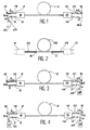
- la figure 1 est une vue schématique d'un mode de réalisation particulier de l'amplificateur optique objet de l'invention, comprenant deux multiplexeurs optiques reliés par une fibre optique en verre fluoré dopé par des ions d'une terre rare,
- la figure 2 est une vue schématique d'un autre mode de réalisation particulier dans lequel les deux multiplexeurs sont reliés par une fibre optique en verre fluoré comportant un tronçon central en verre fluoré dopé par ces ions et, de part et d'autre de celui-ci, des tronçons de fibre optique en verre fluoré non dopé qui sont soudés par fusion au tronçon central,
- la figure 3 illustre schématiquement la possibilité de réaliser un pompage contra-directionnel avec un amplificateur du genre de celui qui est représenté sur la figure 1, et
- la figure 4 illustre schématiquement la possibilité de réaliser un pompage contra-directionnel et un pompage co-directionnel avec un amplificateur du genre de celui qui est représenté sur la figure 1.
- FIG. 1 is a schematic view of a particular embodiment of the optical amplifier which is the subject of the invention, comprising two optical multiplexers connected by an optical fiber made of fluorinated glass doped with ions of rare earth,
- FIG. 2 is a schematic view of another particular embodiment in which the two multiplexers are connected by an optical fiber made of fluorinated glass comprising a central section of fluorinated glass doped with these ions and, on either side of that here, sections of optical fiber made of undoped fluorinated glass which are welded by fusion to the central section,
- FIG. 3 schematically illustrates the possibility of carrying out a contra-directional pumping with an amplifier of the kind of that which is represented in FIG. 1, and
- FIG. 4 schematically illustrates the possibility of carrying out a contra-directional pumping and a co-directional pumping with an amplifier of the kind of that which is represented in FIG. 1.
L'amplificateur conforme à l'invention, qui est schématiquement représenté sur la figure 1, comprend :
- une fibre optique 2 en verre fluoré, dont le coeur est dopé par des ions d'une terre rare,
- un premier multiplexeur optique 4, de type "2 vers 1", comprenant deux fibres optiques d'entrée 6 et 8, constituées par des fibres optiques de silice, et une fibre optique de sortie constituée par la fibre optique 2 (dont une extrémité est ainsi montée dans le multiplexeur 4), et
- un deuxième multiplexeur optique 10, de type "2 vers 1", comprenant une fibre optique d'entrée constituée également par la fibre optique 2 (dont l'autre extrémité est ainsi montée dans ce multiplexeur 10) et deux fibres optiques de
sortie 12 et 14, constituées par des fibres optiques de silice.
- an
optical fiber 2 made of fluorinated glass, the core of which is doped with ions of a rare earth, - a first
optical multiplexer 4, of the "2 to 1" type, comprising two inputoptical fibers 6 and 8, constituted by silica optical fibers, and an output optical fiber constituted by the optical fiber 2 (one end of which is thus mounted in the multiplexer 4), and - a second
optical multiplexer 10, of the "2 to 1" type, comprising an input optical fiber also constituted by optical fiber 2 (the other end of which is thus mounted in this multiplexer 10) and two outputoptical fibers
Dans l'exemple représenté sur la figure 1, l'amplificateur optique conforme à l'invention est inséré dans une ligne optique constituée par une fibre optique 16 en silice standard dans laquelle se propage un signal optique S.In the example shown in FIG. 1, the optical amplifier according to the invention is inserted into an optical line constituted by an
La fibre optique 16 est interrompue pour l'insertion de cet amplificateur optique.The
Une partie 16a de la fibre 16 est optiquement couplée à la fibre optique 6 de cet amplificateur par une soudure par fusion 18 et l'autre partie 16b de cette fibre optique 16 est optiquement couplée à la fibre optique 12 de l'amplificateur par une soudure par fusion 20.A
On munit également l'amplificateur optique de la figure 1 d'un laser de pompage 22 comportant une fibre optique de sortie en silice standard 24 et cette dernière est soudée par fusion à la fibre optique 8 au point A.The optical amplifier of FIG. 1 is also fitted with a pumping
Les fibres 2, 6, 8, 12 et 14 sont monomodes et ont le même diamètre de mode et ce dernier est inférieur au diamètre de mode des fibres 16 et 24 (également monomodes).
Les soudures 18 et 20 et les soudures en A et B sont réalisées de façon à conduire à des pertes inférieures à 0,3 dB.The
Le signal optique SA, résultant de l'amplification du signal S par l'amplificateur de la figure 1, sort de ce dernier par la fibre 12 pour se propager dans la fibre 16.The optical signal SA, resulting from the amplification of the signal S by the amplifier of the FIG. 1, leaves the latter via
Dans l'exemple de la figure 1, le pompage optique est co-directionnel (le rayonnement de pompage P fourni par le laser 22 se propage dans le même sens que le signal S).In the example of FIG. 1, the optical pumping is co-directional (the pumping radiation P supplied by the
Le rayonnement de pompage résiduel R est transmis par la fibre optique 14.The residual pumping radiation R is transmitted by the
Pour réaliser l'amplificateur optique de la figure 1, il convient de fabriquer les deux multiplexeurs optiques 4 et 10.To make the optical amplifier of FIG. 1, it is necessary to manufacture the two
Ceci est réalisable par l'homme du métier (il existe des fabricants, par exemple la Société J.D.S., de multiplexeurs optiques à lentilles de silice, de type "2 vers 1", à deux fibres d'entrée standard en silice et une fibre de sortie standard également en silice, et il suffit de modifier la fabrication de tels multiplexeurs en montant une fibre de sortie en verre fluoré dopé et en montant des fibres d'entrée en silice de même diamètre de mode que cette fibre de sortie.This is achievable by a person skilled in the art (there are manufacturers, for example the JDS Company, of optical multiplexers with silica lenses, of the "2 to 1" type, with two standard input fibers made of silica and a fiber of standard output also in silica, and it suffices to modify the manufacture of such multiplexers by mounting an output fiber in doped fluorinated glass and by mounting input fibers in silica of the same mode diameter as this output fiber.
L'extrémité de la fibre de sortie placée dans ce multiplexeur est polie perpendiculairement ou obliquement à son axe.The end of the output fiber placed in this multiplexer is polished perpendicular or oblique to its axis.
On commence ainsi par fabriquer le multiplexeur 4 muni des fibres 6 et 8 et de la fibre 2.We start by manufacturing the
La transition "silice-verre fluoré" se fait donc par l'intermédiaire des lentilles du multiplexeur 4.The “silica-fluorinated glass” transition therefore takes place via the lenses of the
Dans une variante de réalisation qui est schématiquement illustrée par la figure 2, on fabrique le multiplexeur optique 4 avec une fibre monomode de sortie 30 en verre fluoré non dopé.In an alternative embodiment which is schematically illustrated in FIG. 2, the
De la même façon, on fabrique le multiplexeur optique 10 avec une fibre optique monomode d'entrée 32 en verre fluoré non dopé et l'on soude par fusion les extrémités libres des fibres 30 et 32 respectivement aux extrémités d'un tronçon de fibre optique monomode 28 en verre fluoré dopé par une terre rare (les points de raccordement portant respectivement les références B et C sur la figure 2).In the same way, the
On précise que, dans le cas de la figure 2, les fibres 6, 8, 12, 14, 30 et 32 ont le même diamètre de mode que les fibres de silice standard 16 et 24 et que la fibre 28 a un diamètre de mode inférieur.It is specified that, in the case of FIG. 2, the
Ceci facilite le montage des multiplexeurs 4 et 10.This facilitates the mounting of
En revenant à la fabrication de l'amplificateur de la figure 1, lorsque le multiplexeur optique 4 est réalisé, on détermine la longueur optimale de la fibre amplificatrice (fibre en verre fluoré dopé).Returning to the manufacture of the amplifier of FIG. 1, when the
Cette détermination est réalisée par examen de l'émission spontanée amplifiée à l'aide d'un analyseur de spectre optique.This determination is made by examining the amplified spontaneous emission using an optical spectrum analyzer.
Ensuite, on monte le multiplexeur 10 (identique au multiplexeur 4) à l'extrémité libre de la fibre optique 2, cette fibre 2 entrant ainsi dans le multiplexeur 10.Next, the multiplexer 10 (identical to the multiplexer 4) is mounted at the free end of the
L'extrémité de cette fibre 2 qui se trouve dans ce multiplexeur 10 est polie perpendiculairement ou obliquement à son axe optique.The end of this
Comme précédemment, la transition "verre fluoré-silice" se fait ici par l'intermédiaire des lentilles (non représentées) que comporte le multiplexeur 10.As before, the transition from “fluorinated glass to silica” takes place here by means of the lenses (not shown) that the
L'amplificateur optique conforme à l'invention, qui est représenté sur la figure 1, a une structure symétrique.The optical amplifier according to the invention, which is shown in Figure 1, has a symmetrical structure.
De plus, l'amplificateur de la figure 1 permet avantageusement le filtrage du rayonnement résiduel de pompage R à la sortie de cet amplificateur, grâce au filtre optique (non représenté) que comporte le multiplexeur 10.Furthermore, the amplifier of FIG. 1 advantageously allows the filtering of the residual pumping radiation R at the output of this amplifier, thanks to the optical filter (not shown) that the
Il est ainsi possible de surveiller le fonctionnement du laser de pompage 22 en montant des moyens de surveillance appropriés (non représentés) à la sortie de la fibre optique 14.It is thus possible to monitor the operation of the pumping
La structure de l'amplificateur représenté sur la figure 1 permet également d'utiliser un pompage contra-directionnel comme le montre schématiquement la figure 3.The structure of the amplifier shown in FIG. 1 also makes it possible to use contra-directional pumping as shown schematically in FIG. 3.
Sur cette dernière, on voit un amplificateur optique identique à celui qui est représenté sur la figure 1 à ceci près que l'extrémité libre de la fibre 14 est soudée par fusion, au point D, à la fibre optique monomode de sortie 36 d'un laser de pompage 38, cette fibre 36 étant une fibre en silice standard.On the latter, we see an optical amplifier identical to that shown in Figure 1 except that the free end of the
De plus, dans le cas de la figure 3, l'extrémité libre de la fibre 8 n'est plus reliée à un laser de pompage.In addition, in the case of Figure 3, the free end of the
On réalise alors un pompage contra-directionnel et le rayonnement de pompage résiduel R se propage dans la fibre optique 8.A counter-directional pumping is then carried out and the residual pumping radiation R propagates in the
Dans la variante de réalisation de la figure 4, les fibres 8 et 14 sont respectivement couplées à des lasers de pompage 40 et 38 pour réaliser à la fois un pompage co-directionnel et un pompage contra-directionnel.In the alternative embodiment of FIG. 4, the
Le laser 40 comporte une fibre monomode de sortie standard en silice 42 qui est soudée à la fibre 8 par fusion au point E.The
Dans une variante de réalisation de l'amplificateur représenté sur la figure 1, on fabrique le multiplexeur 10 sans filtre optique ni fibre optique 14, ce qui revient à fabriquer simplement une transition verre fluoré-silice.In an alternative embodiment of the amplifier shown in FIG. 1, the
Claims (8)
- Optical fibre incorporating a fluoride glass optical fibre doped in such a way as to be able to amplify a light signal (S) when a pumping radiation (P) is injected into the fibre, said amplifier being characterized in that it also comprises:- a 2 to 1-type optical multiplexer (4) having on the one hand two silica optical fibres (6, 8) and on the other a single fluoride glass optical fibre (2, 30-28-32),
whereof at least one section is doped in such a way as to constitute said doped fluoride glass fibre, said multiplexer adapting the mode diameter of the silica fibres to the mode diameter of its fluoride glass fibre,- at least one other silica optical fibre (12, 14) and- an optical coupling means (10) between the latter and the fluoride glass fibre, said coupling means serving to adapt the mode diameter of said other silica fibre to the mode diameter of the fluoride glass fibre, the light signal (S) passing from a silica fibre located on one side of the amplifier to a silica fibre located on the other side thereof, whilst the pumping radiation (P) is injected by at least one silica fibre of the amplifier, which is not said latter silica fibres. - Amplifier according to claim 1, characterized in that the optical coupling means is another 2 to 1-type optical multiplexer (10) having on the one hand two silica optical fibres (12, 14) and on the other the fluoride glass fibre (2, 30-28-32).
- Amplifier according to either of the claims 1 and 2, characterized in that the core of said section is doped by ions of at least one rare earth.
- Amplifier according to any one of the claims 1 to 3, characterized in that the fluoride glass optical fibre (2) is doped over its entire length.
- Amplifier according to any one of the claims 1 to 3, characterized in that the fluoride glass optical fibre comprises a fluoride glass optical fibre section (28) doped in such a way as to be able to amplify the light signal and, on two sides of said section, two other undoped, fluoride glass optical fibre sections (30, 32).
- Process for the production of an optical amplifier incorporating a fluoride glass optical fibre doped so as to be able to amplify a light signal (S) when a pumping radiation (P) is injected into the fibre, said process being characterized in that it comprises the following stages:- a 2 to 1 optical multiplexer (4) is produced having on the one hand two silica optical fibres (6, 8) and on the other a fluoride glass optical fibre (2, 30-28-32), whereof at least one section is doped so as to constitute said doped fluoride glass fibre, said multiplexer serving to adapt the mode diameter of the silica fibres to the mode diameter of its fluoride glass fibre and- an optical coupling is brought about between the fluoride glass fibre (2, 30-28-32) and at least one other silica optical fibre (12, 14), said coupling being carried out in such a way as to adapt the mode diameter of said other silica fibre to the mode diameter of the fluoride glass fibre.
- Process according to claim 6, characterized in that a standard silica optical fibre is welded to each of said silica optical fibres and another standard silica optical fibre is welded to said other silica optical fibre, the mode diameter of the fluoride glass optical fibre being equal to the mode diameter of said silica optical fibres and said other silica optical fibre and smaller than the mode diameter of the standard silica fibres.
- Process according to either of the claims 6 and 7, characterized in that the ends of the fluoride glass fibre are polished perpendicularly or obliquely to its axis.
Applications Claiming Priority (2)
| Application Number | Priority Date | Filing Date | Title |
|---|---|---|---|
| FR9309165 | 1993-07-26 | ||
| FR9309165A FR2708354B1 (en) | 1993-07-26 | 1993-07-26 | Optical fiber optic amplifier in doped fluorinated glass and method of manufacturing this amplifier. |
Publications (2)
| Publication Number | Publication Date |
|---|---|
| EP0637109A1 EP0637109A1 (en) | 1995-02-01 |
| EP0637109B1 true EP0637109B1 (en) | 1996-11-20 |
Family
ID=9449625
Family Applications (1)
| Application Number | Title | Priority Date | Filing Date |
|---|---|---|---|
| EP94401706A Expired - Lifetime EP0637109B1 (en) | 1993-07-26 | 1994-07-25 | Doped fluoride glassfiber optical amplifier and method for its manufacture |
Country Status (6)
| Country | Link |
|---|---|
| US (1) | US5473713A (en) |
| EP (1) | EP0637109B1 (en) |
| JP (1) | JPH07147441A (en) |
| CA (1) | CA2128755A1 (en) |
| DE (1) | DE69400947T2 (en) |
| FR (1) | FR2708354B1 (en) |
Families Citing this family (8)
| Publication number | Priority date | Publication date | Assignee | Title |
|---|---|---|---|---|
| DE19641522A1 (en) * | 1996-09-30 | 1998-04-02 | Deutsche Telekom Ag | Method for compensating the dispersion of fluoride-based fiber lasers in the second optical window |
| US6362916B2 (en) * | 1998-09-25 | 2002-03-26 | Fiver Laboratories | All fiber gain flattening optical filter |
| US6964731B1 (en) | 1998-12-21 | 2005-11-15 | Cardinal Cg Company | Soil-resistant coating for glass surfaces |
| EP1126567A1 (en) * | 2000-01-31 | 2001-08-22 | Alcatel | An optical fibre amplifier |
| US20030202770A1 (en) * | 2002-01-03 | 2003-10-30 | Garito Anthony F. | Optical waveguide amplifiers |
| KR100744545B1 (en) * | 2005-12-12 | 2007-08-01 | 한국전자통신연구원 | All-fiber laser device for mid-infrared wavelength band |
| JP2010199563A (en) * | 2009-01-27 | 2010-09-09 | Fujikura Ltd | Optical amplifier and resonator |
| CN113759463A (en) * | 2020-06-04 | 2021-12-07 | 华为技术有限公司 | Optical device constituting optical fiber amplifier, and method of manufacturing the same |
Family Cites Families (8)
| Publication number | Priority date | Publication date | Assignee | Title |
|---|---|---|---|---|
| JP2546711B2 (en) * | 1988-12-22 | 1996-10-23 | 国際電信電話株式会社 | Er-doped optical fiber laser device |
| US4962995A (en) * | 1989-06-16 | 1990-10-16 | Gte Laboratories Incorporated | Glasses for high efficiency erbium (3+) optical fiber lasers, amplifiers, and superluminescent sources |
| GB9001394D0 (en) * | 1990-01-22 | 1990-03-21 | British Telecomm | Fibre amplifiers |
| FR2661783A1 (en) * | 1990-05-02 | 1991-11-08 | Monerie Michel | OPTICAL DEVICE FOR THE EMISSION AND AMPLIFICATION OF LIGHT IN THE ACTIVE 1260-1234NM RANGE CONTAINING PRASEODYM. |
| JPH04371911A (en) * | 1991-06-21 | 1992-12-24 | Hitachi Ltd | Optical isolator and fiber optical amplifier with added rare earth |
| FR2678740B1 (en) * | 1991-07-02 | 1994-06-10 | Alcatel Nv | AMPLIFIER WITH OPTICAL FIBER AMPLIFIER. |
| US5351335A (en) * | 1991-08-26 | 1994-09-27 | Nippon Telegraph And Telephone Corporation | Optical fiber for optical amplifier |
| US5299210A (en) * | 1992-04-28 | 1994-03-29 | Rutgers University | Four-level multiply doped rare earth laser system |
-
1993
- 1993-07-26 FR FR9309165A patent/FR2708354B1/en not_active Expired - Fee Related
-
1994
- 1994-07-25 JP JP6172634A patent/JPH07147441A/en active Pending
- 1994-07-25 EP EP94401706A patent/EP0637109B1/en not_active Expired - Lifetime
- 1994-07-25 DE DE69400947T patent/DE69400947T2/en not_active Expired - Lifetime
- 1994-07-25 CA CA002128755A patent/CA2128755A1/en not_active Abandoned
- 1994-07-25 US US08/279,546 patent/US5473713A/en not_active Expired - Lifetime
Also Published As
| Publication number | Publication date |
|---|---|
| DE69400947T2 (en) | 1997-06-05 |
| JPH07147441A (en) | 1995-06-06 |
| FR2708354A1 (en) | 1995-02-03 |
| FR2708354B1 (en) | 1995-09-01 |
| US5473713A (en) | 1995-12-05 |
| EP0637109A1 (en) | 1995-02-01 |
| CA2128755A1 (en) | 1995-01-27 |
| DE69400947D1 (en) | 1997-01-02 |
Similar Documents
| Publication | Publication Date | Title |
|---|---|---|
| EP1326105B1 (en) | Optical coupler for multimode pump | |
| EP0603042A1 (en) | Monolithical optical system for coupling between optical fiber and optoelectronic component | |
| FR2765752A1 (en) | FIBER OPTICAL AMPLIFIER FOR REACHING A HIGH GAIN OF A SMALL SIGNAL | |
| EP0534819A1 (en) | Method for limiting coupling losses between an optical monomode fibre and an optical system having different spot size diameters respectively | |
| EP0511069B1 (en) | Optical amplifier in the spectral range from 1.26 to 1.34 micron | |
| FR2678075A1 (en) | Optical isolator, optical circuit and amplifier using optical fibre doped with a rare earth | |
| FR2740620A1 (en) | OPTICAL AMPLIFIER, AND TOOL COMPRISING THE SAME | |
| EP0637109B1 (en) | Doped fluoride glassfiber optical amplifier and method for its manufacture | |
| EP0346232B1 (en) | Process and system for joining optical fibres without Fresnel-reflection, variable optical attenuator and system, using the same for measurement of the influence of the reflection-rate on an optical line | |
| FR2706633A1 (en) | Optical device comprising an optical fiber primer and method for its manufacture | |
| FR2688641A1 (en) | INTEGRATED OPTICAL AMPLIFIER AND LASER IMPLEMENTING SUCH AMPLIFIER. | |
| EP0665615B1 (en) | Fluoride glass optical amplifier and method for its manufacture | |
| WO2013131877A1 (en) | Device for converting the transverse spatial profile of intensity of a light beam, preferably using a microstructured optical fibre | |
| FR2768267A1 (en) | Optical amplifier system | |
| US6217204B1 (en) | Optical fiber assembly and light amplification coupler having rare earth doped light amplification medium and related method of making | |
| FR2805899A1 (en) | MULTIMODE SHEATH FIBER OPTICAL AMPLIFICATION IN BAND C | |
| CA2440911A1 (en) | Optical amplification structure with an integrated optical system and amplification housing integrating one such structure | |
| FR2756993A1 (en) | Optical repeater amplification and transmission system for broadband long distance communication | |
| FR2860599A1 (en) | Optical coupler device for e.g. multi-core single mode fiber, has section of pure silicon fiber welded to free end of section of index gradient fiber and/or inserted between end of multi-core fiber and end of index gradient fiber | |
| EP1289077A1 (en) | Dual core fiber with rare earth doped ring | |
| EP1030412B1 (en) | Optical amplifier | |
| WO2002027369A1 (en) | Injection device for optical fibre and preparation method | |
| FR2827969A1 (en) | Optical telecommunications monomode fibre optic unit having two fibre sections and associated expansion mode each end and maintenance section optical function mechanism setting. | |
| EP1074074A1 (en) | Doped fibre optical amplifier for 1600 nm band | |
| FR2822313A1 (en) | Dual core optical fibre includes power exchange zone enabling filtering and controlled interference between signals in two cores |
Legal Events
| Date | Code | Title | Description |
|---|---|---|---|
| PUAI | Public reference made under article 153(3) epc to a published international application that has entered the european phase |
Free format text: ORIGINAL CODE: 0009012 |
|
| AK | Designated contracting states |
Kind code of ref document: A1 Designated state(s): DE GB IT |
|
| 17P | Request for examination filed |
Effective date: 19950710 |
|
| GRAG | Despatch of communication of intention to grant |
Free format text: ORIGINAL CODE: EPIDOS AGRA |
|
| GRAH | Despatch of communication of intention to grant a patent |
Free format text: ORIGINAL CODE: EPIDOS IGRA |
|
| 17Q | First examination report despatched |
Effective date: 19960401 |
|
| GRAH | Despatch of communication of intention to grant a patent |
Free format text: ORIGINAL CODE: EPIDOS IGRA |
|
| GRAA | (expected) grant |
Free format text: ORIGINAL CODE: 0009210 |
|
| RAP1 | Party data changed (applicant data changed or rights of an application transferred) |
Owner name: FRANCE TELECOM |
|
| AK | Designated contracting states |
Kind code of ref document: B1 Designated state(s): DE GB IT |
|
| REF | Corresponds to: |
Ref document number: 69400947 Country of ref document: DE Date of ref document: 19970102 |
|
| ITF | It: translation for a ep patent filed |
Owner name: PROPRIA PROTEZIONE PROPR. IND. |
|
| GBT | Gb: translation of ep patent filed (gb section 77(6)(a)/1977) |
Effective date: 19970124 |
|
| PLBE | No opposition filed within time limit |
Free format text: ORIGINAL CODE: 0009261 |
|
| STAA | Information on the status of an ep patent application or granted ep patent |
Free format text: STATUS: NO OPPOSITION FILED WITHIN TIME LIMIT |
|
| 26N | No opposition filed | ||
| REG | Reference to a national code |
Ref country code: GB Ref legal event code: IF02 |
|
| PGFP | Annual fee paid to national office [announced via postgrant information from national office to epo] |
Ref country code: IT Payment date: 20060731 Year of fee payment: 13 |
|
| PG25 | Lapsed in a contracting state [announced via postgrant information from national office to epo] |
Ref country code: IT Free format text: LAPSE BECAUSE OF NON-PAYMENT OF DUE FEES Effective date: 20070725 |
|
| REG | Reference to a national code |
Ref country code: GB Ref legal event code: 732E Free format text: REGISTERED BETWEEN 20100930 AND 20101006 |
|
| PGFP | Annual fee paid to national office [announced via postgrant information from national office to epo] |
Ref country code: DE Payment date: 20110729 Year of fee payment: 18 |
|
| PGFP | Annual fee paid to national office [announced via postgrant information from national office to epo] |
Ref country code: GB Payment date: 20120625 Year of fee payment: 19 |
|
| PG25 | Lapsed in a contracting state [announced via postgrant information from national office to epo] |
Ref country code: DE Free format text: LAPSE BECAUSE OF NON-PAYMENT OF DUE FEES Effective date: 20130201 |
|
| REG | Reference to a national code |
Ref country code: DE Ref legal event code: R119 Ref document number: 69400947 Country of ref document: DE Effective date: 20130201 |
|
| GBPC | Gb: european patent ceased through non-payment of renewal fee |
Effective date: 20130725 |
|
| PG25 | Lapsed in a contracting state [announced via postgrant information from national office to epo] |
Ref country code: GB Free format text: LAPSE BECAUSE OF NON-PAYMENT OF DUE FEES Effective date: 20130725 |