EP0636844B1 - Method and apparatus for maintaining a snow surface - Google Patents
Method and apparatus for maintaining a snow surface Download PDFInfo
- Publication number
- EP0636844B1 EP0636844B1 EP94115422A EP94115422A EP0636844B1 EP 0636844 B1 EP0636844 B1 EP 0636844B1 EP 94115422 A EP94115422 A EP 94115422A EP 94115422 A EP94115422 A EP 94115422A EP 0636844 B1 EP0636844 B1 EP 0636844B1
- Authority
- EP
- European Patent Office
- Prior art keywords
- air
- snow surface
- snow
- dehumidifying
- ice
- Prior art date
- Legal status (The legal status is an assumption and is not a legal conclusion. Google has not performed a legal analysis and makes no representation as to the accuracy of the status listed.)
- Expired - Lifetime
Links
- 238000000034 method Methods 0.000 title claims description 22
- 238000001816 cooling Methods 0.000 claims description 26
- 238000001179 sorption measurement Methods 0.000 claims description 15
- 230000007246 mechanism Effects 0.000 claims description 5
- 238000009834 vaporization Methods 0.000 claims description 5
- 239000002245 particle Substances 0.000 description 20
- 238000007796 conventional method Methods 0.000 description 17
- XLYOFNOQVPJJNP-UHFFFAOYSA-N water Substances O XLYOFNOQVPJJNP-UHFFFAOYSA-N 0.000 description 14
- 238000002844 melting Methods 0.000 description 10
- 230000008018 melting Effects 0.000 description 10
- 230000002265 prevention Effects 0.000 description 8
- 238000005057 refrigeration Methods 0.000 description 8
- 239000006260 foam Substances 0.000 description 7
- 238000007710 freezing Methods 0.000 description 6
- 230000009467 reduction Effects 0.000 description 6
- 238000010276 construction Methods 0.000 description 5
- 239000000463 material Substances 0.000 description 5
- 239000000654 additive Substances 0.000 description 4
- 230000000996 additive effect Effects 0.000 description 3
- 230000015572 biosynthetic process Effects 0.000 description 3
- 239000003795 chemical substances by application Substances 0.000 description 3
- 230000003750 conditioning effect Effects 0.000 description 3
- 230000006866 deterioration Effects 0.000 description 3
- 239000000203 mixture Substances 0.000 description 3
- 230000009471 action Effects 0.000 description 2
- 230000008901 benefit Effects 0.000 description 2
- 230000005540 biological transmission Effects 0.000 description 2
- 239000012267 brine Substances 0.000 description 2
- 230000000694 effects Effects 0.000 description 2
- 238000002156 mixing Methods 0.000 description 2
- HPALAKNZSZLMCH-UHFFFAOYSA-M sodium;chloride;hydrate Chemical compound O.[Na+].[Cl-] HPALAKNZSZLMCH-UHFFFAOYSA-M 0.000 description 2
- 238000010521 absorption reaction Methods 0.000 description 1
- 238000004378 air conditioning Methods 0.000 description 1
- 230000001143 conditioned effect Effects 0.000 description 1
- 239000000498 cooling water Substances 0.000 description 1
- 238000006073 displacement reaction Methods 0.000 description 1
- 238000005265 energy consumption Methods 0.000 description 1
- 239000010419 fine particle Substances 0.000 description 1
- 230000008014 freezing Effects 0.000 description 1
- 238000010298 pulverizing process Methods 0.000 description 1
- 239000011347 resin Substances 0.000 description 1
- 229920005989 resin Polymers 0.000 description 1
- 238000007873 sieving Methods 0.000 description 1
- 239000007787 solid Substances 0.000 description 1
- 238000003756 stirring Methods 0.000 description 1
- 230000009466 transformation Effects 0.000 description 1
- 239000002699 waste material Substances 0.000 description 1
Images




Classifications
-
- F—MECHANICAL ENGINEERING; LIGHTING; HEATING; WEAPONS; BLASTING
- F25—REFRIGERATION OR COOLING; COMBINED HEATING AND REFRIGERATION SYSTEMS; HEAT PUMP SYSTEMS; MANUFACTURE OR STORAGE OF ICE; LIQUEFACTION SOLIDIFICATION OF GASES
- F25C—PRODUCING, WORKING OR HANDLING ICE
- F25C3/00—Processes or apparatus specially adapted for producing ice or snow for winter sports or similar recreational purposes, e.g. for sporting installations; Producing artificial snow
- F25C3/04—Processes or apparatus specially adapted for producing ice or snow for winter sports or similar recreational purposes, e.g. for sporting installations; Producing artificial snow for sledging or ski trails; Producing artificial snow
-
- F—MECHANICAL ENGINEERING; LIGHTING; HEATING; WEAPONS; BLASTING
- F25—REFRIGERATION OR COOLING; COMBINED HEATING AND REFRIGERATION SYSTEMS; HEAT PUMP SYSTEMS; MANUFACTURE OR STORAGE OF ICE; LIQUEFACTION SOLIDIFICATION OF GASES
- F25C—PRODUCING, WORKING OR HANDLING ICE
- F25C2303/00—Special arrangements or features for producing ice or snow for winter sports or similar recreational purposes, e.g. for sporting installations; Special arrangements or features for producing artificial snow
- F25C2303/042—Snow making by using solid ice, e.g. ice crushing
Definitions
- the present invention relates to a method of maintaining a snow surface and an apparatus therefor.
- conventional method e.g. the Japanese laid-open utility model gazette No. 63-113866 and U.S.P. 2,676471, to be hereinafter referred to as conventional method 1
- water and compressed gas mainly, air
- conventional method 1 water and compressed gas (mainly, air) both sufficiently refrigerated are sprayed through a nozzle, such that the sprayed mixture is frozen by adiabatic expansion at an atmosphere under the freezing point temperature to be formed into fine ice particles and then the ice particles are accumulated to form a snow surface.
- ice cubes are prepared and these cubes are crushed by means of an ice crusher machine to be rendered into fine ice particles. Then, these particles are sprayed around to be accumulated for forming a snow surface.
- a weter-receiving bank as an ice-making bank is constructed along a skiing slope. Under a below-freezing point temperature, water is frozen on the ice-making bank to form an ice surface thereon. Then, this ice surface is crushed off by a crusher into fine ice particles and concurrently therewith the ice particles are scattered about onto the skiing slope beside the ice-making bank to form an artificial snow surface.
- an ice layer is formed on a skiing slope by sprinking water under a below-freezing point temperature. Then, the formed ice layer is crushed by means of a roller equipped with a sieving machine driven on the layer to form the layer into fine ice particles.
- the Japanese PCT-laid-open patent application No. 62-503118 discloses a still further method (to be hereinafter referred to as the conventional method 5).
- this method mixture of water and surface-activating agent is stirred to foam. And, this foam is laid out on a skiiing slope to be frozen at a below-freezing point temperature. Thereafter, a roller is driven on the frozen foam in order to crush it into ice particles forming a snow surface.
- the above-identified PCT application discloses a further method (to be hereinafter referred to as the conventional method 6).
- the above-described foam generated by stirring the mixture of the water and surface-activating agent is laid out on a flexible grating preliminarily refrigerated by a freezer unit, so that the foam is frozen in the grating. Thereafter, a roller is passed on the frozen foam to crush it into ice particles forming a snow surface.
- a further method of forming and maintaining an artificial snow layer is disclosed in EP 0,508,752, wherein a refrigerating device is operated to prevent melting of an artificial snow layer and the humidity of the atmosphere above the snow layer is controlled by an air conditioning unit (10) including a temperature controlling coil and a single dehumidifier.
- the conventional method 1 has the significant shortcoming of requiring a great amount of energy for realizing and maintaining the below-freezing point atmosphere regardless of the current climate condition.
- the conventional method 2 has the problem of requiring a great amount of labor and costs for the transport of the ice cubes separately prepared.
- the conventional method 3 has the problem of requiring a significant amount of space for constructing the water-receiving surface along the skiing slope.
- the conventional method 4 suffers the problem that the roller often fails to pulvarize the ice layer into sufficiently small particles. Further, if a fine sieve is used to select fine, i.e. good ice particles alone, there will occur a great amount of waste of the unused particles. Conversely, if a rough sieve is used for the sake of economy, there will occur significant quality deterioration, i.e. roughness in the obtained ice particles.
- the snow surface is formed by pulverizing the frozen foam by means of the roller. Accordingly, the resultant snow surface tends to be too compacted and hard which provides a skier with an uncomfortable and unnatural skiing feel, as compared with a snow surface formed by natural show.
- the conventional method 5 further suffers the same problem of the method 1, i.e. the problem of requiring an enormous amount of energy for artificially creating the below-freezing point atmosphere regardless of the natural climate.
- the primary object of the present invention is to provide a method and an apparatus for effectively maintaining a snow surface.
- a method of maintaining the artificial snow surface comprises dehumidifying air (AT) adjacent above the snow surface by means of a dehumidifying means to restrict frosting of moisture present in said air on said snow surface, wherein said dehumidifying means includes an adsorption type dehumidifying unit and a cooling type dehumidifying unit, said adsorption type dehumidifying unit being selectively used when an ambience temperature is relatively low, said cooling type dehumidifying unit being selectively used when the ambience temperature is relatively high.
- an apparatus for maintaining a snow surface in accordance with the method of the invention by dehumidifying air adjacent above the snow surface by dehumidifying means so as to restrict frosting of moisture present in said air on said snow surface, wherein said dehumidifying means includes an adsorption type dehumidifying unit and a cooling type dehumidifying unit.
- the method prevents frosting of the air on the snow surface (i.e. transfer of the heat from the air to the snow, such that the method can prevent also disadvantageous increase in the load in the refrigeration of the snow surface.
- the refrigerating machine inevitably suffers low operation efficiency in refrigerating the snow surface because the machine has to provide a very low temperature for this purpose. Therefore, such effective prevention of increase in the load can achieve significant reduction in the running cost of the system.
- an adsorption type dehumidifying device is used, there occurs increase in the temperature of the processed air in association with its dehumidifying operation. This temperature increase can be effectively utilized for preventing excessive refrigeration of the snow surface due to absorption of cold from the ambience air, which tends to occur during the winter season. Such excessive refrigeration of the snow surface will result in deterioration in the quality of the snow. Then, the prevention of excessive refrigeration can provide the skier with comfortable and smooth skiing feel.
- a cooling type dehumidifying device is also used as dehumidifying means.
- the device When this cooling type dehumidifying device is used, there occurs decrease of the temperature in the processed air. Accordingly, the device can effectively restrict transfer of the heat from the ambience air to the snow surface, which heat transfer often occurs during the summer season. Thus, in this case too, the snow surface can be maintained at good skiing condition through the prevention of frosting of water content present in the ambience air on the snow surface, and further much energy can be saved through prevention of melting of the snow.
- the adsorption type dehumidifying device is selectively used when the ambience air is at a relatively low temperature and the cooling type dehumidifying device is selectively used when the air is at a relatively high temperature.
- the use of the adsorption type dehumidifying device provides the advantage of restricting excessive refrigeration of the snow surface during the winter season while the use of the cooling type dehumidifying device provides the advantage of restricting the heat transfer from the ambience air to the snow surface during a warm season.
- the two types of dehumidifying devices can achieve both the comfortable skiing feel and the running cost reduction.
- Fig. 1 shows a construction of a conventional indoor skiing slope.
- Reference numeral 1 denotes a housing.
- Numeral 2 denotes a sloped floor incorporating a heat insulating means.
- Numeral 3 denotes a refrigerating-medium pipe embedded substantially over the entire surface of the sloped floor 2.
- Numeral 4 denotes a refrigerating machine for refrigerating a refrigerating medium (brine) to e.g. - 14 to - 22 degrees in Celsius.
- Numeral 5 denotes an air-conditioner.
- Numeral 6 denotes a cooling coil (for circulating cooling water at + 5 to + 7 degrees in Celsius.
- Numeral 7 denotes a dehumidifying unit incorporated in the air-conditioner 5.
- Numeral 8 denotes an air passage for combining an indoor air AT introduced through an air intake opening 9 with an outdoor air. introduced an outdoor-air flow passage 10 and introducing this combined air into the air-conditioner 5 and then feeding the conditioned air into the ineterior of the housing through an air outlet opening 11.
- Numeral 12 denotes an air exhaust passage for exhausting the indoor air AT by an amount corresponding to the amount of the introduced outdoor air.
- a snow surface 13a For forming a snow surface 13a, an appropriate amount of water is sprayed over an entire surface of the sloped floor 2. Then, the sprayed water is frozen by the refrigerating-medium pipe 3. These operations are repeated to form a multiplicity of thin ice layers on the sloped floor 2 until an ice layer 14 having a predetermined thickness (a) is obtained.
- the amount of the water sprayed at one time should be so controlled that the water will immediately freeze on the sloped floor 2 without falling off the floor.
- the predetermined thickness (a) of the ice layer 14 preferably ranges between 100 and 150 mm.
- a self-propelling type ice crusher machine 15 is driven on the entire surface of the ice layer 14. As the machine 15 being propelled, the machine 15 shaves a surface of the ice layer 14 to generate artificial snow consisting of fine ice particles. At the same time, as the propelling machine 15 leaves behind the generated artificial snow on the remain of the ice layer 14, an artificial snow layer 13 is formed on the ice layer 14, such that these layers 13 and 14 together form the snow surface 13a.
- the dimension of the particle of the artificial snow can be varied through adjustment of a shaving depth of a rotary shaving blade 18a relative to the ice layer 14, in order to obtain such snow particle as most suitable for skiing.
- the ice crusher machine 15 is driven on the ice layer 14 or on the formed snow layer 13 while shaving the surface thereof for a plurality of times. With these repeated operations, the snow layer 13 gradually increases in its thickenss (here, the afore-mentioned snow surface denotes such layer having its air content increased due to the transformation of the ice into the fine particles in comparison with the ice layer 14).
- the thickness (b) of the snow layer 13 preferably ranges between 20 and 50 mm.
- such additive is to be used, such material should be selected as is inexpensive and as will cause only minimal reduction in the heat transmitting ratio in the ice layer 14. Alternately, such reduction in the heat transmission ratio can be restricted by employing an additive consisting of very small particles to reduce the amount of the air present in the ice layer 14.
- the formation of the ice layer 14 and the prevention of melting of the ice layer 14 and the snow layer 13 are effected by means of refrigeration via the refrigerating-medium pipe 3 as described above.
- a cooling coil 6 is operated to cool the indoor air to provide skiers with comfortable atmosphere as well as to help the refrigerating-medium pipe 3 to prevent melting of the snow surface 13a.
- the dehumidifying unit 7 In conditioning the indoor air AT, in addition to the cooling of the air AT by means of the cooling coil 6 when the ambient temperature is high, because the indoor air AT becomes moist by the breaths of the skiers and by the introduction of new outdoor air, the dehumidifying unit 7 is operated to dehumidify the moisted indoor air AT so as to maintain the dew point of the indoor air AT below the temperature of the snow surface 13a ranging between - 2 and - 3 degrees in Celsius thereby to maintain good skiing condition of the snow surface 13a.
- the machine 15 includes a machine body 15a mounting a pair of right and left sledges 16 and a pair of right and left propelling wheels 17 as a propelling means for propelling the machine body 15a on the ice layer 14 or the snow surface 13a.
- This propelling means need not be mounted to the machine body 15a. Instead, it is conceivable to propel the machine body 15a by means of a separate propelling means.
- rotary shaving blades 18A as a blade means for shaving the surface of the snow surface 14.
- the propelling wheels 17 serve to propel the machine body 15a straightway when these wheels 17 are rotated at a same speed in a same direction. Also, when these wheels 17 are rotated at different speeds or directions, these wheels 17 serve to steer the machine body 15a.
- the plurality of shaving blades 18A are arranged in a radial pattern on a lower face of a rotary disc rotatable about a vertical axis P extending substantially normal to the ice layer 14. As these blades 18A are driven to rotate via the rotary disc 19 by a motor 20, the rotating blades 18A shave or cut the surface of the ice layer 14 by a certain depth and the cut ice as artificial snow is sent radially outwards to be left on the remain of the ice layer 14.
- a blade edge 18a formed at a lower edge of each shaving blade 18A is inclined with an outer portion thereof relative to the radius of the rotary disc 19 being formed higher than an inner portion, such that the blade edge 18a when used shaves the ice layer 14 with an inclination relative to the direction of the thickenss of this ice layer 14.
- the inclined blade edges 18a cut deeper at the lower sides thereof.
- the blade edges 18a can cut deep with one shaving action thereby to efficiently generate a large amount of artificial snow.
- the angle (A) of the inclination i.e. the inclination angle provided for smooth sending of the generated artificial snow outwards relative to the radius of the rotary disc 19
- the angle (B) of the shaving blade 18A preferably ranges between 20 and 40 degrees.
- the clearance angle (C) of the shaving blade 18A preferably ranges between 5 and 10 degrees.
- the shaving blades 18A are replaceable when necessary. Also, at a center of the radial pattern arrangement of the shaving blades 18A, there is attached a cylinder member 21 for preventing intrusion and resultant clogging of the generated artificial snow.
- the rotation speed of the rotary disc 19 is adjustable by an inverter control on the motor 20. Through this adjustment of the rotation speed, the quality of the artificial snow is adjusted.
- the above-described ice crusher machine 15 is operated by a wireless remote control operation effected from an indoor monitor room R.
- the shaving blades 18A are driven at a predetermined speed to shave the surface of the ice layer 14 while the machine 15 is propelled at a predetermined propelling speed over the entire surface of the ice layer 14 or the snow surface 13a, thereby to form a large area of the snow layer 13 having a predetermined thickenss (b) which consequently forms the snow surface 13a (i.e. skiing slope).
Landscapes
- Engineering & Computer Science (AREA)
- Physics & Mathematics (AREA)
- Mechanical Engineering (AREA)
- Thermal Sciences (AREA)
- General Engineering & Computer Science (AREA)
- Road Paving Structures (AREA)
Description
- The present invention relates to a method of maintaining a snow surface and an apparatus therefor.
- According to one conventional method (e.g. the Japanese laid-open utility model gazette No. 63-113866 and U.S.P. 2,676471, to be hereinafter referred to as conventional method 1) of forming an artificial snow surface, water and compressed gas (mainly, air) both sufficiently refrigerated are sprayed through a nozzle, such that the sprayed mixture is frozen by adiabatic expansion at an atmosphere under the freezing point temperature to be formed into fine ice particles and then the ice particles are accumulated to form a snow surface.
- According to another conventional method known from e.g. the Japenese published patent gazette No. 61-31393 (to be hereinafter referred to as the conventional method 2), ice cubes are prepared and these cubes are crushed by means of an ice crusher machine to be rendered into fine ice particles. Then, these particles are sprayed around to be accumulated for forming a snow surface.
- According to a still further conventional method known from the Japanese laid-open patent gazette No. 56-133566 (to be hereinafter referred to as the conventional method 3), a weter-receiving bank as an ice-making bank is constructed along a skiing slope. Under a below-freezing point temperature, water is frozen on the ice-making bank to form an ice surface thereon. Then, this ice surface is crushed off by a crusher into fine ice particles and concurrently therewith the ice particles are scattered about onto the skiing slope beside the ice-making bank to form an artificial snow surface.
- According to a further conventional method (to be hereinafter referred to as the conventional method 4), an ice layer is formed on a skiing slope by sprinking water under a below-freezing point temperature. Then, the formed ice layer is crushed by means of a roller equipped with a sieving machine driven on the layer to form the layer into fine ice particles.
- The Japanese PCT-laid-open patent application No. 62-503118 (PCT/AU86/00158) discloses a still further method (to be hereinafter referred to as the conventional method 5). According to this method, mixture of water and surface-activating agent is stirred to foam. And, this foam is laid out on a skiiing slope to be frozen at a below-freezing point temperature. Thereafter, a roller is driven on the frozen foam in order to crush it into ice particles forming a snow surface.
- The above-identified PCT application discloses a further method (to be hereinafter referred to as the conventional method 6). According to this method, the above-described foam generated by stirring the mixture of the water and surface-activating agent is laid out on a flexible grating preliminarily refrigerated by a freezer unit, so that the foam is frozen in the grating. Thereafter, a roller is passed on the frozen foam to crush it into ice particles forming a snow surface.
- A further method of forming and maintaining an artificial snow layer is disclosed in EP 0,508,752, wherein a refrigerating device is operated to prevent melting of an artificial snow layer and the humidity of the atmosphere above the snow layer is controlled by an air conditioning unit (10) including a temperature controlling coil and a single dehumidifier.
- The above-described conventional methods have drawbacks to be specifically described next.
- The
conventional method 1 has the significant shortcoming of requiring a great amount of energy for realizing and maintaining the below-freezing point atmosphere regardless of the current climate condition. - The
conventional method 2 has the problem of requiring a great amount of labor and costs for the transport of the ice cubes separately prepared. - The conventional method 3 has the problem of requiring a significant amount of space for constructing the water-receiving surface along the skiing slope. The
conventional method 4 suffers the problem that the roller often fails to pulvarize the ice layer into sufficiently small particles. Further, if a fine sieve is used to select fine, i.e. good ice particles alone, there will occur a great amount of waste of the unused particles. Conversely, if a rough sieve is used for the sake of economy, there will occur significant quality deterioration, i.e. roughness in the obtained ice particles. - With the
conventional methods - The
conventional method 5 further suffers the same problem of themethod 1, i.e. the problem of requiring an enormous amount of energy for artificially creating the below-freezing point atmosphere regardless of the natural climate. - Taking the above-described states of the art into consideration, the primary object of the present invention is to provide a method and an apparatus for effectively maintaining a snow surface.
- A method of maintaining the artificial snow surface according to the present invention, comprises dehumidifying air (AT) adjacent above the snow surface by means of a dehumidifying means to restrict frosting of moisture present in said air on said snow surface, wherein said dehumidifying means includes an adsorption type dehumidifying unit and a cooling type dehumidifying unit, said adsorption type dehumidifying unit being selectively used when an ambience temperature is relatively low, said cooling type dehumidifying unit being selectively used when the ambience temperature is relatively high.
- In accordance with a further aspect of the invention there is provided an apparatus for maintaining a snow surface in accordance with the method of the invention by dehumidifying air adjacent above the snow surface by dehumidifying means so as to restrict frosting of moisture present in said air on said snow surface, wherein said dehumidifying means includes an adsorption type dehumidifying unit and a cooling type dehumidifying unit.
- Functions and effects of this method and apparatus will be described next.
- In conditioning the ambience air present adjacent above the snow surface, the method prevents frosting of the air on the snow surface (i.e. transfer of the heat from the air to the snow, such that the method can prevent also disadvantageous increase in the load in the refrigeration of the snow surface. Especially, the refrigerating machine inevitably suffers low operation efficiency in refrigerating the snow surface because the machine has to provide a very low temperature for this purpose. Therefore, such effective prevention of increase in the load can achieve significant reduction in the running cost of the system.
- Because an adsorption type dehumidifying device is used, there occurs increase in the temperature of the processed air in association with its dehumidifying operation. This temperature increase can be effectively utilized for preventing excessive refrigeration of the snow surface due to absorption of cold from the ambience air, which tends to occur during the winter season. Such excessive refrigeration of the snow surface will result in deterioration in the quality of the snow. Then, the prevention of excessive refrigeration can provide the skier with comfortable and smooth skiing feel.
- Further, a cooling type dehumidifying device is also used as dehumidifying means.
- When this cooling type dehumidifying device is used, there occurs decrease of the temperature in the processed air. Accordingly, the device can effectively restrict transfer of the heat from the ambience air to the snow surface, which heat transfer often occurs during the summer season. Thus, in this case too, the snow surface can be maintained at good skiing condition through the prevention of frosting of water content present in the ambience air on the snow surface, and further much energy can be saved through prevention of melting of the snow.
- According to the invention, the adsorption type dehumidifying device is selectively used when the ambience air is at a relatively low temperature and the cooling type dehumidifying device is selectively used when the air is at a relatively high temperature.
- With this arrangement, the use of the adsorption type dehumidifying device provides the advantage of restricting excessive refrigeration of the snow surface during the winter season while the use of the cooling type dehumidifying device provides the advantage of restricting the heat transfer from the ambience air to the snow surface during a warm season. Thus, such selective use between the two types of dehumidifying devices can achieve both the comfortable skiing feel and the running cost reduction.
- Further, it is conceivable to control the humidyfing means so as to equate a vapor pressure of the snow surface with a vapor pressure of the ambience air.
- With this further arrangement, it becomes possible to avoid frosting phenomenon on the snow surface which would otherwise occur when the vapor pressure of the ambience air is higher than that of the snow surface. In this manner, through the prevention of frosting on the snow surface-as well as of water-vaporization from the snow surface both of which impair smoothness of the snow surface, the snow surface can be maintained at a good skiing condition more reliably and effectively.
- In particular, when the snow surface is generated by forming a snow layer containing solid particles of e.g. resin material, with such water-vaporization from the snow surface, the deterioration in the smoothness of the snow surface takes place very significantly, since the soild particles become exposed on the surface to the ambience. Accordingly, the above-described prevention of water-vaporization from the snow surface will be very much appreciated in such case.
- Further objects and effects of the invention will become more apparent from the following more detailed description of the embodiments of the invention with reference to the accompanying drawings.
-
- Fig. 1 is a view showing a construction of a conventional system of an indoor artificial skiing slope,
- Fig. 2 is a partially cutaway plane view of an ice crushing machine,
- Fig. 3 is a front section of the ice crushing machine,
- Fig. 4 is an enlarged section of a shaving blade, and
- Fig. 5 is a plane view illustrating an operation of the ice crushing machine,
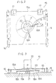
- Figs. 6 and 7 illustrate another ice crushing machine, with Fig. 6 being a partially cutaway plane view and Fig. 7 being a front section of the machine, respectively,
- Figs. 8 and 9 illustrate a further ice crushing machine, with Fig. 8 being a partially cutaway plane view and Fig. 7 being a front section of the machine, respectively,
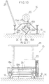
- Figs. 10 and 11 illustrate a still further ice crushing, machine, with Fig. 10 being a side section and Fig. 11 being a front section of the machine of this embodiment, respectively, and
- - Fig. 12 is a view illustrating a system according to the present invention.
-
- A preferred embodiment of the present invention will now be described in details with reference to Fig.12.
- Fig. 1 shows a construction of a conventional indoor skiing slope.
Reference numeral 1 denotes a housing.Numeral 2 denotes a sloped floor incorporating a heat insulating means. Numeral 3 denotes a refrigerating-medium pipe embedded substantially over the entire surface of the slopedfloor 2.Numeral 4 denotes a refrigerating machine for refrigerating a refrigerating medium (brine) to e.g. - 14 to - 22 degrees in Celsius.Numeral 5 denotes an air-conditioner.Numeral 6 denotes a cooling coil (for circulating cooling water at + 5 to + 7 degrees in Celsius. Numeral 7 denotes a dehumidifying unit incorporated in the air-conditioner 5.Numeral 8 denotes an air passage for combining an indoor air AT introduced through anair intake opening 9 with an outdoor air. introduced an outdoor-air flow passage 10 and introducing this combined air into the air-conditioner 5 and then feeding the conditioned air into the ineterior of the housing through anair outlet opening 11.Numeral 12 denotes an air exhaust passage for exhausting the indoor air AT by an amount corresponding to the amount of the introduced outdoor air. - For forming a
snow surface 13a, an appropriate amount of water is sprayed over an entire surface of the slopedfloor 2. Then, the sprayed water is frozen by the refrigerating-medium pipe 3. These operations are repeated to form a multiplicity of thin ice layers on thesloped floor 2 until anice layer 14 having a predetermined thickness (a) is obtained. - The amount of the water sprayed at one time should be so controlled that the water will immediately freeze on the
sloped floor 2 without falling off the floor. - Further, the predetermined thickness (a) of the
ice layer 14 preferably ranges between 100 and 150 mm. - After the formation of the
ice layer 14, a self-propelling typeice crusher machine 15 is driven on the entire surface of theice layer 14. As themachine 15 being propelled, themachine 15 shaves a surface of theice layer 14 to generate artificial snow consisting of fine ice particles. At the same time, as the propellingmachine 15 leaves behind the generated artificial snow on the remain of theice layer 14, anartificial snow layer 13 is formed on theice layer 14, such that theselayers snow surface 13a. - The dimension of the particle of the artificial snow can be varied through adjustment of a shaving depth of a
rotary shaving blade 18a relative to theice layer 14, in order to obtain such snow particle as most suitable for skiing. - Depending on the necessity, the
ice crusher machine 15 is driven on theice layer 14 or on the formedsnow layer 13 while shaving the surface thereof for a plurality of times. With these repeated operations, thesnow layer 13 gradually increases in its thickenss (here, the afore-mentioned snow surface denotes such layer having its air content increased due to the transformation of the ice into the fine particles in comparison with the ice layer 14). - The thickness (b) of the
snow layer 13 preferably ranges between 20 and 50 mm. - Incidentally, it is conceivable to mix a surface-activating agent or a water-swelling material in the water to form the
ice layer 14 for the purpose of facilitating the generation of the aritificial snow by shaving the ice layer. However, with such mixing material, there occurs reduction in the heat transmission ratio of theice layer 14, which results in decrease in the refrigerating temperature necessary for the refrigerating-medium pipe 3 to prevent melting of thesnow layer 13 on theice layer 14. For this reason, there will inevitably occur increase in the device costs as well as in the running costs, in addition to the cost of the mixing material per se. - Accordingly, it is more economically advantageous if water without such additive is used as the water to be sprayed for the formation of the
ice layer 14. - If such additive is to be used, such material should be selected as is inexpensive and as will cause only minimal reduction in the heat transmitting ratio in the
ice layer 14. Alternately, such reduction in the heat transmission ratio can be restricted by employing an additive consisting of very small particles to reduce the amount of the air present in theice layer 14. - The formation of the
ice layer 14 and the prevention of melting of theice layer 14 and thesnow layer 13 are effected by means of refrigeration via the refrigerating-medium pipe 3 as described above. In this connection, if the ambience temperature (i.e. the outdoor air in this embodiment) is relatively high and a large amount of heat can enter the housing (mainly during the summer season), a coolingcoil 6 is operated to cool the indoor air to provide skiers with comfortable atmosphere as well as to help the refrigerating-medium pipe 3 to prevent melting of thesnow surface 13a. - In conditioning the indoor air AT, in addition to the cooling of the air AT by means of the cooling
coil 6 when the ambient temperature is high, because the indoor air AT becomes moist by the breaths of the skiers and by the introduction of new outdoor air, the dehumidifying unit 7 is operated to dehumidify the moisted indoor air AT so as to maintain the dew point of the indoor air AT below the temperature of thesnow surface 13a ranging between - 2 and - 3 degrees in Celsius thereby to maintain good skiing condition of thesnow surface 13a. - The construction of the
ice crusher machine 15 will be particularly described with reference to Figs. 2 and 4. - The
machine 15 includes amachine body 15a mounting a pair of right and leftsledges 16 and a pair of right and left propellingwheels 17 as a propelling means for propelling themachine body 15a on theice layer 14 or thesnow surface 13a. This propelling means need not be mounted to themachine body 15a. Instead, it is conceivable to propel themachine body 15a by means of a separate propelling means. Further, to a lower portion of themachine body 15a, there are attachedrotary shaving blades 18A as a blade means for shaving the surface of thesnow surface 14. - The propelling
wheels 17 serve to propel themachine body 15a straightway when thesewheels 17 are rotated at a same speed in a same direction. Also, when thesewheels 17 are rotated at different speeds or directions, thesewheels 17 serve to steer themachine body 15a. - The plurality of
shaving blades 18A are arranged in a radial pattern on a lower face of a rotary disc rotatable about a vertical axis P extending substantially normal to theice layer 14. As theseblades 18A are driven to rotate via therotary disc 19 by amotor 20, therotating blades 18A shave or cut the surface of theice layer 14 by a certain depth and the cut ice as artificial snow is sent radially outwards to be left on the remain of theice layer 14. - A
blade edge 18a formed at a lower edge of eachshaving blade 18A is inclined with an outer portion thereof relative to the radius of therotary disc 19 being formed higher than an inner portion, such that theblade edge 18a when used shaves theice layer 14 with an inclination relative to the direction of the thickenss of thisice layer 14. With this arrangement in operation, the inclined blade edges 18a cut deeper at the lower sides thereof. As a result, the blade edges 18a can cut deep with one shaving action thereby to efficiently generate a large amount of artificial snow. - Incidentally, the angle (A) of the inclination (i.e. the inclination angle provided for smooth sending of the generated artificial snow outwards relative to the radius of the rotary disc 19) between the radius of the
rotary disc 19 and theshaving blade 18A preferably ranges between 15 and 25 degrees. Further, the scooping angle (B) of theshaving blade 18A preferably ranges between 20 and 40 degrees. The clearance angle (C) of theshaving blade 18A preferably ranges between 5 and 10 degrees. - The
shaving blades 18A are replaceable when necessary. Also, at a center of the radial pattern arrangement of theshaving blades 18A, there is attached acylinder member 21 for preventing intrusion and resultant clogging of the generated artificial snow. - The rotation speed of the
rotary disc 19 is adjustable by an inverter control on themotor 20. Through this adjustment of the rotation speed, the quality of the artificial snow is adjusted. - The above-described
ice crusher machine 15 is operated by a wireless remote control operation effected from an indoor monitor room R. By this remote control operation, theshaving blades 18A are driven at a predetermined speed to shave the surface of theice layer 14 while themachine 15 is propelled at a predetermined propelling speed over the entire surface of theice layer 14 or thesnow surface 13a, thereby to form a large area of thesnow layer 13 having a predetermined thickenss (b) which consequently forms thesnow surface 13a (i.e. skiing slope). - Some other embodiments will be specifically described next.
- (a) The refrigerating means incorporated in the
floor 2 is not limited to the brine refrigerating-medium pipe 3. Various other types of refrigerating systems can be employed. For instance, it is conceivable to employ such refrigerating system as freezes and prevents melting of thesnow surface 13a by refrigerating the air immediately above thesnow surface 13a. - (b) As mentioned hereinbefore, the water to be
sprayed over the
floor 2 to form theice layer 14 thereon can contain various kids of additives depending on the convenience. - (c) The ice crusher machine for shaving the surface
of the
ice layer 14 to form the artificial snow consisting of fine ice particles is not limited to the self-propelling typeice crusher machine 15 disclosed in the foregoing embodiment. It is possible to employ other types of machines, one of which will be particularly described later. - (d) The method of forming an artificial snow surface can be used also for forming an artificial snow surface outdoors.
- (e) The
snow surface 13a to be formed by the method of the invention is not limited to the above-described snow surface sloped in one direction. Instead, it is also possible to form a snow surface with many ups and downs for use in the practice of the Nordic type skiiing or a flat snow surface. - (f) With respect to the construction of the ice
crusher machine of the invention, the foregoing
embodiment dislcoses the propelling means for
propelling the
machine body 15a comprised of the combination of thesledges 16 and the propellingwheels 17. Instead, the propelling means can be a crawler type propelling device. Further, the machine can be of a manually propelled type instead of the self-propelled type disclosed in the foregoing embodiment. - (g) In the ice crusher machine, the shaving blades
for shaving the surface of the
ice layer 14 can be of various types to be described next. - (i) As shown in Figs. 6 and 7, a
cylinder member 22 is coaxially attached to the lower face of therotary disc 19 which is similar to the one used in the foregoing embodiment. On an outer periphery of thiscylinder member 22, there are attached a plurality of shavingblades 18B havingblade edges 18b extending outwards along the radius of thedisc 19. Themotor 20 is used for rotating therotary disc 19 so that theblades 18B cut theice layer 14 in the direction normal to the direction of the thickness of the layer 14 (i.e. the direction in parallel with the propelling direction of themachine body 15a). Further, with this shaving, the generated artificial snow is sent outwards relative to the radius of therotary disc 19 to be left on theice layer 14. Areference numeral 23 denotes a bottom plate for closing a lower terminal end of thecylinder member 22 for preventing intrusion and resultant clogging of the generated artificial snow in the member 22.In the above-described construction of this further embodiment, the scooping angle (D) of theshaving blade 18B preferably ranges between 20 and 40 degrees. - (ii) As shown in Figs. 8 and 9, as auxiliary
shaving blades, a pair of
shaving blades 18A (substantially the same as those in the first embodiment) having downwardly orientedblade edges 18a are attached with 180 degree displacement therebetween to the lower face of therotary disc 19. In addition, as main shaving blades, a plurality of shavingblades 18B havingshaving edges 18b extending radially outwards are attached to the lower face of therotary disc 19 adjacent the outer periphery of thedisc 19. In operation, as theauxiliary shaving blades 18A cut theice layer 14 along its thickness to support sinking movements of themain blades 18B into the surface of theice layer 14, themain blades 18B cut theice layer 14 in the direction normal to the thickness direction of the layer 14 (i.e. in parallel with the propelling direction of themachine body 15a). In association with the shaving actions of the blades, the generated artificial snow is sent outwards (i.e. rearwardly of themachine body 15a relative to the propelling direction of themachine body 15a) to be left on the remain of theice layer 14. - (iii) As shown in Figs. 10 and 11, the plurality
of
shaving blades 18A are attached to arotary drum 24 rotatable about an axis Q extending substantially in parallel with theice layer 14, so that theblades 18A rotate about the axis Q to shave the surface of theice layer 14. Areference numeral 25 denotes a handle for an operator. - (h) An embodiment of the inventions method
of maintaing the snow surface will be particularly
described next.
As shown in Fig. 12, the system includes an
adsorption
type dehumidifying unit 28 and adamper mechanism 33 for selectively providing two conditions, i.e. a condition for causing the combined air comprised of the indoor air AT introduced through theair intake opening 10 and the outdoor air to pass through the air-conditioner 5 and a further condition for causing the combined air to pass through the dehumidifying unit 28.Melting of thesnow surface 13a is restricted by maintaining thesnow surface 13a at a predetermined low temperature (ts) (e.g. - 2 to - 3 degrees in Celsius) throughout the year through the refrigeration by the refrigerating-medium pipe 3 on theice layer 14 and thesnow layer 13. With this, thesnow surface 13a can be maintained at a good skiing condition. Further, if the ambience temperature (the outdoor temperature in the present case) is relatively high and a large amount of heat tends to enter the building interior (mainly in the summer season), the coolingcoil 6 is operated with thedamper mechanism 33 being switched over for the air passage through air-conditioner 5, thereby to provide comfortable indoor atmosphere for the skiers and also to restrict melting of thesnow surface 13a in cooperation with the refrigeration by the refrigerating-medium pipe 3.In conditioning the indoor air AT, in addition to the cooling of the air AT by means of the coolingcoil 6 when the ambient temperature is high, because the indoor air AT becomes moist by the breaths of the skiers and by the introduction of new outdoor air, with thedamper mechanism 33 switched over for the air passage through the air-conditioner 5, the cooling type dehumidifying unit 7 is operated to dehumidify the moisted indoor air AT. Alternately, the adsorptiontype dehumidifying unit 28 is operated with thedamper mechanism 33 being switched over for the air passage through thisunit 28. In either case, the operation is effected so as to maintain the dew point (tp) of the indoor air AT below the temperature (ts) of thesnow surface 13a (i.e. to maintain the condition: tp ≦ ts, in other words, to maintain the vapor pressure of the indoor air AT lower than the vapor pressure of thesnow surface 13a), thereby to avoid frosting of the moist on thesnow surface 13a consequently to maintain a good skiing condition of the snow surface 13a.The selective uses of the cooling type dehumidifying unit 7 7 and the adsorptiontype dehumidifying unit 28 will be particularly described next.The cooling type dehumidifying unit 7 operable to cool the processed air while dehumidifying it is used when the ambience temperature is high and a large amount of heat tends to enter the building interior (mainly during the summer season), so that the cooled and dehumidified air is effectively used for maintaining comfortable indoor atmosphere by restricting intrusion of the heat into the interior. Further, this type of dehumidifying unit is used also for restricting transfer of the heat from the indoor air AT to thesnow surface 13a thus aiding the prevention of melting of the snow surface 13a.Incidentally, in the operation of the air-conditioner 5, on some occasions, both the cooling type dehumidifying unit 7 and thecooling coil 6 are operated; and on other occasions, only one of these is operated, depending on the particular temperature load and humidity load present.In contrast to the above-described cooling type dehumidifying unit 7, the adsorptiontype dehumidifying unit 28 in which there occurs increase in the processed air in association with the dehumidifying operation is used when the ambience temperature is low (mainly during the winter season) so as to effectively utilize the air temperature rise associated with the dehumidifying operation for restricting excessive reduction in the indoor air temperature thereby to maintain comfortable indoor atmosphere.Refering more particularly to the dehumidifying operation, in this dehumidifying operation by either the cooling type dehumidfying unit 7 or the adsorptiontype dehumidifying unit 28, the unit is so controlled as to equate the vapor pressure of thesnow surface 13a with the vapor pressure of the indoor air AT. With this further arrangement, it becomes possible to restrict both frosting on the snow surface and water-vaporization from the snow surface which impair smoothness of the snow surface.Another unillustrated refrigerating machine than the refrigeratingmachine 4 is connected to thecooling coil 6 of the air-conditioner 5. More particularly, the use of theaforementioned refrigerating machine 4 which does no have a good coefficient of performance because of the requirement for producing a very low temperature for preventing of melting of theice layer 14 and thesnow layer 13 is limited for this purpose of refrigerating theice layer 14 and thesnow layer 13, so that this refrigeratingmachine 4 can be of a relatively small capacity to save energy consumption. - (j) Instead of dehumidifying the entirety of the
indoor air AT as described in the foregoing
embodiments, it is also conceivable to dehumidify only
a portion of the air present within an appropriate
altitude range from the
snow surface 13a. - (k) The
snow surface 13a can be formed of the artificial snow generated by the various methods described hereinbefore and can also be formed of natural snow. - (l) The use of the snow surface formed by the method of the present invention is not limited to the use of skiing. The surface can be used for any other application.
-
Claims (4)
- A method of maintaining a snow surface (13a) having the step of dehumidifying air (AT) adjacent above the snow surface by means of a dehumidifying means (7,28) to restrict frosting of moisture present in said air on said snow surface, wherein said dehumidifying means includes an adsorption type dehumidifying unit (28) and a cooling type dehumidifying unit (7), said adsorption type dehumidifying unit (28) being selectively used when an ambience temperature is relatively low, said cooling type dehumidifying unit (7) being selectively used when the ambience temperature is relatively high.
- A method as claimed in claim 1, wherein in said dehumidifying step, said dehumidifying means is so controlled as to substantially equate a vapor pressure of the snow surface (13a) with a water-vaporization pressure of the air.
- An apparatus for maintaining a snow surface in accordance with the method of claim 1 or 2 by dehumidifying air adjacent above the snow surface by dehumidifying means so as to restrict frosting of moisture present in said air on said snow surface, wherein said dehumidifying means includes an adsorption type dehumidifying unit (28) and a cooling type dehumidifying unit (7) connected in parallel.
- An apparatus as claimed in claim 3, wherein said snow surface (13a) is disposed inside a housing (1), and the apparatus further includes a damper mechanism (33) for selectively providing a condition for causing combined air comprised of the indoor air (AT) and outdoor air to pass through said adsorption type dehumidifying unit (28) and a further condition for causing the combined air to pass through an air conditioner (5) having said cooling type dehumidifying unit (7).
Priority Applications (1)
| Application Number | Priority Date | Filing Date | Title |
|---|---|---|---|
| DE69132883T DE69132883D1 (en) | 1991-11-12 | 1991-11-12 | Method and device for maintaining snow cover |
Applications Claiming Priority (1)
| Application Number | Priority Date | Filing Date | Title |
|---|---|---|---|
| EP91310436A EP0541867A1 (en) | 1991-11-12 | 1991-11-12 | Method of forming artificial snow surface, ice crusher machine used in the method and method of maintaining snow surface |
Related Parent Applications (2)
| Application Number | Title | Priority Date | Filing Date |
|---|---|---|---|
| EP91310436A Division EP0541867A1 (en) | 1991-11-12 | 1991-11-12 | Method of forming artificial snow surface, ice crusher machine used in the method and method of maintaining snow surface |
| EP91310436.0 Division | 1991-11-12 |
Publications (2)
| Publication Number | Publication Date |
|---|---|
| EP0636844A1 EP0636844A1 (en) | 1995-02-01 |
| EP0636844B1 true EP0636844B1 (en) | 2001-12-19 |
Family
ID=8208467
Family Applications (2)
| Application Number | Title | Priority Date | Filing Date |
|---|---|---|---|
| EP91310436A Withdrawn EP0541867A1 (en) | 1991-11-12 | 1991-11-12 | Method of forming artificial snow surface, ice crusher machine used in the method and method of maintaining snow surface |
| EP94115422A Expired - Lifetime EP0636844B1 (en) | 1991-11-12 | 1991-11-12 | Method and apparatus for maintaining a snow surface |
Family Applications Before (1)
| Application Number | Title | Priority Date | Filing Date |
|---|---|---|---|
| EP91310436A Withdrawn EP0541867A1 (en) | 1991-11-12 | 1991-11-12 | Method of forming artificial snow surface, ice crusher machine used in the method and method of maintaining snow surface |
Country Status (1)
| Country | Link |
|---|---|
| EP (2) | EP0541867A1 (en) |
Families Citing this family (4)
| Publication number | Priority date | Publication date | Assignee | Title |
|---|---|---|---|---|
| FR2700835B1 (en) * | 1993-01-26 | 1995-04-21 | Technip Cie | Snow production process and installation. |
| NO337419B1 (en) * | 2014-03-04 | 2016-04-11 | Roy Erik Eriksson | Cooling device for cooling solid material and / or freezing liquid |
| CN104964500B (en) * | 2015-07-05 | 2017-06-06 | 金烜伊 | A kind of grinding roller formula trash ice snowmaker |
| CN108992810B (en) * | 2018-08-31 | 2023-06-13 | 泉州魔力神工具制造有限公司 | Movable fresh air conditioner |
Family Cites Families (12)
| Publication number | Priority date | Publication date | Assignee | Title |
|---|---|---|---|---|
| US2058919A (en) * | 1933-01-17 | 1936-10-27 | B F Sturtevant Co | Air conditioning apparatus |
| GB421431A (en) * | 1933-03-29 | 1934-12-20 | James Govan | Improvements relating to ice rinks |
| US2239190A (en) * | 1933-12-01 | 1941-04-22 | Gen Motors Corp | Air conditioning method and apparatus |
| US2203560A (en) * | 1938-04-06 | 1940-06-04 | Carrier Corp | Air conditioning method |
| US3990260A (en) * | 1975-04-04 | 1976-11-09 | Eustis William E C | Low-temperature dehumidifier |
| US3983713A (en) * | 1975-05-05 | 1976-10-05 | Maccracken Calvin D | Method of creating and outdoor ice slab in summer weather and of reducing energy requirements for indoor and outdoor ice rinks |
| US4345439A (en) * | 1980-02-20 | 1982-08-24 | Vencraft Corp. | Snowmaking method and apparatus |
| GB2186673B (en) * | 1985-06-04 | 1989-07-19 | Permasnow Ltd | Method for making artificial snow |
| FR2607909B1 (en) * | 1986-12-05 | 1992-01-17 | York Froid Ind | METHOD FOR SNOWFALLING ARTIFICIAL ALPINE OR NORDIC SKI TRACKS AND MEANS FOR IMPLEMENTING THE METHOD |
| CA1332517C (en) * | 1988-06-22 | 1994-10-18 | Malcolm Geoege Clulow | Snow making equipment |
| NZ232751A (en) * | 1989-03-01 | 1992-03-26 | Andrew Boyd French | Making snow: placing nozzle of snowmaking machine into temperature controlled environment |
| EP0508752B1 (en) * | 1991-04-11 | 1996-02-14 | Taikisha, Ltd. | Method of forming an artificial snow layer |
-
1991
- 1991-11-12 EP EP91310436A patent/EP0541867A1/en not_active Withdrawn
- 1991-11-12 EP EP94115422A patent/EP0636844B1/en not_active Expired - Lifetime
Also Published As
| Publication number | Publication date |
|---|---|
| EP0541867A1 (en) | 1993-05-19 |
| EP0636844A1 (en) | 1995-02-01 |
Similar Documents
| Publication | Publication Date | Title |
|---|---|---|
| US5381668A (en) | Method of maintaining artificial snow surface | |
| US5327738A (en) | Method of forming and maintaining artificial snow layer | |
| US4813598A (en) | Snow making apparatus and method for making snow | |
| US20130264032A1 (en) | Snow/ ice making & preserving methods | |
| CN112930463B (en) | Method and device for producing snowfall | |
| US4914923A (en) | Method of covering artificial alpine- or nordic-skiing tracks with snow and means for implementing the method | |
| WO1989012793A1 (en) | Snow making equipment | |
| JP2751008B2 (en) | Ice making equipment | |
| US4919331A (en) | Snow making apparatus and method for making snow | |
| EP0541867A1 (en) | Method of forming artificial snow surface, ice crusher machine used in the method and method of maintaining snow surface | |
| AU2010257201B2 (en) | Snow making method and apparatus | |
| AU654756B2 (en) | Method of maintaining snow surface | |
| EP1444469B1 (en) | Snow making | |
| JPH0436563A (en) | Method of forming artificial snow surface and ice cutting device for artificial snow surface forming process | |
| EP0971185A1 (en) | Method and device for producing snow | |
| JP2537021B2 (en) | Artificial snow layer formation method | |
| JPH0711128B2 (en) | Artificial snow layer management method | |
| GB2324596A (en) | Making snow | |
| JP2702658B2 (en) | Anti-freezing device under the skating rink floor | |
| JPH069949A (en) | Artificial snow and prevention of consolidation of artificial snow | |
| JPH03217774A (en) | ice temperature storage | |
| JP3006514B2 (en) | Maintenance method for frozen ice surface and snow maintenance vehicle used for the method | |
| JPH064963B2 (en) | Snow surface maintenance method of artificial facility | |
| JPH04295381A (en) | Artificial skiing ground | |
| KR20180054951A (en) | Snowing booth |
Legal Events
| Date | Code | Title | Description |
|---|---|---|---|
| PUAI | Public reference made under article 153(3) epc to a published international application that has entered the european phase |
Free format text: ORIGINAL CODE: 0009012 |
|
| 17P | Request for examination filed |
Effective date: 19940930 |
|
| AC | Divisional application: reference to earlier application |
Ref document number: 541867 Country of ref document: EP |
|
| AK | Designated contracting states |
Kind code of ref document: A1 Designated state(s): BE DE GB NL |
|
| 17Q | First examination report despatched |
Effective date: 19970520 |
|
| RTI1 | Title (correction) |
Free format text: METHOD AND APPARATUS FOR MAINTAINING A SNOW SURFACE |
|
| GRAG | Despatch of communication of intention to grant |
Free format text: ORIGINAL CODE: EPIDOS AGRA |
|
| RTI1 | Title (correction) |
Free format text: METHOD AND APPARATUS FOR MAINTAINING A SNOW SURFACE |
|
| GRAG | Despatch of communication of intention to grant |
Free format text: ORIGINAL CODE: EPIDOS AGRA |
|
| GRAH | Despatch of communication of intention to grant a patent |
Free format text: ORIGINAL CODE: EPIDOS IGRA |
|
| GRAH | Despatch of communication of intention to grant a patent |
Free format text: ORIGINAL CODE: EPIDOS IGRA |
|
| GRAH | Despatch of communication of intention to grant a patent |
Free format text: ORIGINAL CODE: EPIDOS IGRA |
|
| GRAA | (expected) grant |
Free format text: ORIGINAL CODE: 0009210 |
|
| AC | Divisional application: reference to earlier application |
Ref document number: 541867 Country of ref document: EP |
|
| AK | Designated contracting states |
Kind code of ref document: B1 Designated state(s): BE DE GB NL |
|
| PG25 | Lapsed in a contracting state [announced via postgrant information from national office to epo] |
Ref country code: NL Free format text: LAPSE BECAUSE OF FAILURE TO SUBMIT A TRANSLATION OF THE DESCRIPTION OR TO PAY THE FEE WITHIN THE PRESCRIBED TIME-LIMIT Effective date: 20011219 Ref country code: BE Free format text: LAPSE BECAUSE OF FAILURE TO SUBMIT A TRANSLATION OF THE DESCRIPTION OR TO PAY THE FEE WITHIN THE PRESCRIBED TIME-LIMIT Effective date: 20011219 |
|
| REG | Reference to a national code |
Ref country code: GB Ref legal event code: IF02 |
|
| REF | Corresponds to: |
Ref document number: 69132883 Country of ref document: DE Date of ref document: 20020131 |
|
| PG25 | Lapsed in a contracting state [announced via postgrant information from national office to epo] |
Ref country code: DE Free format text: LAPSE BECAUSE OF FAILURE TO SUBMIT A TRANSLATION OF THE DESCRIPTION OR TO PAY THE FEE WITHIN THE PRESCRIBED TIME-LIMIT Effective date: 20020320 |
|
| NLV1 | Nl: lapsed or annulled due to failure to fulfill the requirements of art. 29p and 29m of the patents act | ||
| PLBE | No opposition filed within time limit |
Free format text: ORIGINAL CODE: 0009261 |
|
| STAA | Information on the status of an ep patent application or granted ep patent |
Free format text: STATUS: NO OPPOSITION FILED WITHIN TIME LIMIT |
|
| 26N | No opposition filed | ||
| NLV1 | Nl: lapsed or annulled due to failure to fulfill the requirements of art. 29p and 29m of the patents act | ||
| PGFP | Annual fee paid to national office [announced via postgrant information from national office to epo] |
Ref country code: GB Payment date: 20040930 Year of fee payment: 14 |
|
| PG25 | Lapsed in a contracting state [announced via postgrant information from national office to epo] |
Ref country code: GB Free format text: LAPSE BECAUSE OF NON-PAYMENT OF DUE FEES Effective date: 20051112 |
|
| GBPC | Gb: european patent ceased through non-payment of renewal fee |
Effective date: 20051112 |