EP0636832B1 - Sicherheitskappe, insbesondere für Dampferzeugerbehälter - Google Patents
Sicherheitskappe, insbesondere für Dampferzeugerbehälter Download PDFInfo
- Publication number
- EP0636832B1 EP0636832B1 EP94111694A EP94111694A EP0636832B1 EP 0636832 B1 EP0636832 B1 EP 0636832B1 EP 94111694 A EP94111694 A EP 94111694A EP 94111694 A EP94111694 A EP 94111694A EP 0636832 B1 EP0636832 B1 EP 0636832B1
- Authority
- EP
- European Patent Office
- Prior art keywords
- piston
- safety cap
- bush
- cap according
- groove
- Prior art date
- Legal status (The legal status is an assumption and is not a legal conclusion. Google has not performed a legal analysis and makes no representation as to the accuracy of the status listed.)
- Expired - Lifetime
Links
- 230000002093 peripheral effect Effects 0.000 claims abstract description 4
- 239000002184 metal Substances 0.000 claims description 5
- 239000000463 material Substances 0.000 claims description 3
- 238000006073 displacement reaction Methods 0.000 claims description 2
- 239000004033 plastic Substances 0.000 claims description 2
- 239000005060 rubber Substances 0.000 claims description 2
- 239000012815 thermoplastic material Substances 0.000 claims description 2
- 238000004140 cleaning Methods 0.000 description 4
- 239000012530 fluid Substances 0.000 description 3
- 238000009835 boiling Methods 0.000 description 2
- 230000001680 brushing effect Effects 0.000 description 2
- 230000000994 depressogenic effect Effects 0.000 description 2
- 239000011796 hollow space material Substances 0.000 description 2
- XLYOFNOQVPJJNP-UHFFFAOYSA-N water Substances O XLYOFNOQVPJJNP-UHFFFAOYSA-N 0.000 description 2
- 230000015572 biosynthetic process Effects 0.000 description 1
- 230000006835 compression Effects 0.000 description 1
- 238000007906 compression Methods 0.000 description 1
- 239000011521 glass Substances 0.000 description 1
- 230000005484 gravity Effects 0.000 description 1
- 238000010438 heat treatment Methods 0.000 description 1
- 235000012171 hot beverage Nutrition 0.000 description 1
- 238000010409 ironing Methods 0.000 description 1
- 239000007788 liquid Substances 0.000 description 1
- 238000012986 modification Methods 0.000 description 1
- 230000004048 modification Effects 0.000 description 1
- 239000002991 molded plastic Substances 0.000 description 1
- 230000000284 resting effect Effects 0.000 description 1
- 238000005406 washing Methods 0.000 description 1
Images


Classifications
-
- F—MECHANICAL ENGINEERING; LIGHTING; HEATING; WEAPONS; BLASTING
- F16—ENGINEERING ELEMENTS AND UNITS; GENERAL MEASURES FOR PRODUCING AND MAINTAINING EFFECTIVE FUNCTIONING OF MACHINES OR INSTALLATIONS; THERMAL INSULATION IN GENERAL
- F16J—PISTONS; CYLINDERS; SEALINGS
- F16J13/00—Covers or similar closure members for pressure vessels in general
- F16J13/24—Covers or similar closure members for pressure vessels in general with safety devices, e.g. to prevent opening prior to pressure release
-
- F—MECHANICAL ENGINEERING; LIGHTING; HEATING; WEAPONS; BLASTING
- F22—STEAM GENERATION
- F22B—METHODS OF STEAM GENERATION; STEAM BOILERS
- F22B1/00—Methods of steam generation characterised by form of heating method
- F22B1/28—Methods of steam generation characterised by form of heating method in boilers heated electrically
- F22B1/284—Methods of steam generation characterised by form of heating method in boilers heated electrically with water in reservoirs
Definitions
- This invention relates to a safety cap especially suitable for tanks of steam producing appliances.
- this invention relates to a cap as specified above, incorporating a device suitable to prevent the opening of the tank in the presence of a given steam pressure existing inside it.
- a safety cap for application to a tank of a steam producing appliance is known from EP-A-0 400514. Said disclosed safety cap has the features of the preamble of claim 1.
- the user has at his disposal a handy appliance, capable of delivering a steam flow through which a thorough cleaning of surfaces is obtained; in this way one does not need to have recourse to the traditional and tiresome hand systems, which do not ensure, among other things, that really high levels of hygiene are reached in the cleaning, given the low temperature which cleansing products are traditionally brought to during their utilization.
- Object of this invention is to obviate the aforementioned drawback.
- object of this invention is to provide a safety cap, especially suitable for steam producing appliances, provided with a safety device suitable to prevent the loosening or unscrewing of said cap in the presence of fluids under pressure withing the steam tank or the boiler.
- a further object of this invention is to provide a safety cap furtherly provided with an adjustable exhaust valve, suitable to automatically step in in case of excess pressure inside the tank.
- a further object of this invention is to supply users with a safety cap capable of providing a high degree of reliability and resistence in the long run, and also such as to be easily and economically realizable.
- the safety cap subject matter of this invention suitable in particular for application to a tank of a steam producing appliance, comprising a hollow main support body being longitudinally bored and having a substantially cylindrical shape and a back end for connection to a mouth of the tank, a bush fitted on said body and being integral with an external covering of plastic material, and a piston fitted inside said body for longitudinal displacement between a first position and a second position, wherein said body comprises two or more radial through-holes provided around the circumference thereof with a sphere in each through-hole; two or more longitudinal grooves of hemispheric cross-section are formed along the inner surface of said bush, and a groove is formed around the perimeter of said piston at a location corresponding to the through-holes, when said piston is in said second position, whereby said spheres protrude from said through-holes into said longitudinal groove if said piston is in the first position and said spheres are free to protrude into said peripheral groove, thereby releasing said longitudinal groove, if said piston
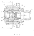
- the safety cap subject matter of this invention is basically constituted by a main support hollow body 12, having a substantially cylindrical shape, a bush 14, fitted on said body, and a piston 16, slidingly positioned within said body 12.
- the latter extends, at one end, forming a smaller diameter tang 12', for the connection, by known means, to the tank or the boiler (not represented) of the steam producing appliance.
- a metal cap 20 is screwed, whose depressed portion 20' engages partly in said body and is connected by means of a generic thread; cap 20 is provided with at least a central hole 22 for exhausting steam.
- bush 14 which, at the opposing end, strikes an annular portion 14' obtained by increases of the diameter of body 12.
- Bush 14 is integral with an external covering 18 from moulded plastic material or the like, which performs the function of an internal attachment of the external grip of cap 10 when the latter is screwed or unscrewed.
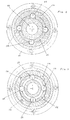
- the inner wall of bush 14 is provided with two or more longitudinally extended grooves 24, having preferably an hemispheric section; in the preferred embodiment of Figs. 1 through 5, said grooves are obtained in number of 4, arranged at 90° relative to one another.
- a through hole 26 is obtained within which a metal sphere 28 is provided whose diameter is slightly smaller that the diameter of said hole.
- the inside of the hollow body 12 circumscribes a cylindrical chamber 30, depressed at the end near tang 12', to form an annular portion 32, to stop the back travel of the mobile piston 16, as will be explained later on.
- Said mobile piston 16, longitudinally provided with a hole having different diameters, is housed in said chamber 30; piston 16, provided at the front end with a portion 16' whose diameter is smaller relatively to the rest of the body, has a whole length shorter than chamber 30, circumscribed frontally by base 20' of cap 20, and on the back by the already mentioned annular portion 32.
- a groove 36 is obtained having, by way of example, a trapezoid section, and whose depth is preferably at least equal to half the diameter of sphere 28; said groove is obtained near the front end of piston 16, along the greater diameter portion of same.
- further annular close grooves 40 are obtained, which house as many toric rings 42 or the like, suitable to realize the pressure tightness between piston 16 and body 12 wherein the former is located.
- a suitably calibrated spring 34 is provided, which tends to keep under tension said piston and, in conditions of absence of steam pressure within cap 10, locks its back end against portion 32 of body 12.
- said piston 16 is advantageously provided with a valve suitable to automatically step in in the presence of excess steam pressure within body 10.
- Said valve is constituted by a ring 44 screwed at the back end of piston 16, on whose front head a gasket 46 is provided, made preferably from rubber or a thermoplastic material.
- Said gasket is made up by a disk having a diameter greater than the diameter of ring 44 and is preferably coupled to a guiding and centering metal support 48; on said support a suitably calibrated spring (50) rests, which extends into the inside of piston 16 striking its smaller diameter front end 52.
- Figs. 1 and 4 show schematically the situation in which there is no pressure in the boiler to which cap 10 is applied; spring 34 pushes piston 16 towards the back wall of body 12, until the latter strikes portion 32.
- Spheres 28 protrude towards the external bush 14 and rest in threads 24, constituting as many elements that drag said bush and the associated covering 18; for the remaining part, said spheres take up holes 26 up to brushing the inner piston 16.
- This arrangement of the mentioned members allow to hand loose and unscrew cap 10, starting from covering 18, which performs the function of a grip and is integral with bush 14. Therefore, the fluid, generally water, to be brought to the boiling point, can be poured into the boiler through hole or holes 22 of cap 20.
- spring 50 inside piston 16 is in condition of utmost extension, so that gasket 46 closes on the hole of ring 44.
- Fig. 3 shows the further situation of automatic opening of the valve integral with cap 10, in the presence of excess steam pressure in the boiler of the appliance.
- the aforementioned figure shows that gasket 46 with the associated front support 48 is removed from the hole obtained on ring 44.
- the high pressure within the boiler actually causes the compression of the suitably calibrated spring 50 and opens the exhaust duct, allowing steam to flow through the hole of ring 44, to distribute within piston 16 and to flow outwards from body 10 through hole 22 of the end cap 20.
- the cap subject matter of this invention ensures the utmost safety, excluding any possibility of intentional or accidental opening in the presence of steam pressure inside the boiler; one can also, depending on the mechanical characteristics of the elastic member inserted between the mobile piston and the end cap, grade at will the effort necessary to loosen or totally remove the safety cap from the support body.
- a safety valve integral with the cap which avoids the necessity of having recourse to further devices for the exhaust of steam, in the presence of a possible excess pressure in the boiler of the appliance.
- a simplified embodiment may provide for a cap lacking the safety valve; said cap might also provide for the realization of the mobile piston integrally with the ring at the back.
- the configuration of the perimetral hollow space provided on the aforementioned piston might be different from what has been described by way of example and illustrated; besides, instead of said hollow space, individual seats might be realized along the external perimeter of said piston in correspondence of the dragging spheres, which piston should then be provided with means suitable to prevent its rotation during the travel within the main support body.
Landscapes
- Engineering & Computer Science (AREA)
- General Engineering & Computer Science (AREA)
- Mechanical Engineering (AREA)
- Life Sciences & Earth Sciences (AREA)
- Sustainable Development (AREA)
- Sustainable Energy (AREA)
- Physics & Mathematics (AREA)
- Thermal Sciences (AREA)
- Pressure Vessels And Lids Thereof (AREA)
- Closures For Containers (AREA)
- Taps Or Cocks (AREA)
Claims (10)
- Sicherheitsverschluß zur Verwendung bei einem Tank einer Dampf erzeugenden Vorrichtung mit einem hohlen Haupttragkörper (12), der in Längsrichtung gebohrt ist und eine im wesentlichen zylindrische Form und ein hinteres Ende (12') zum Anschließen an die Tanköffnung besitzt, einer Hülse (14), die auf dem Körper (12) sitzt und an die eine Außenabdeckung (18) aus Kunststoffmaterial angeformt ist, und einem Kolben (16), der zur Verschiebung in Längsrichtung zwischen einer ersten Stellung und einer zweiten Stellung in den Körper (12) eingesetzt ist, dadurch gekennzeichnet, daß der Körper (12) zwei oder mehr auf seinem Umfang vorgesehene radiale Durchgangsöffnungen (26) mit jeweils einer Kugel (28) darin besitzt, zwei oder mehr Längsnuten (24) mit halbkreisförmigem Querschnitt längs der Innenfläche der Hülse (14) ausgebildet sind und eine Nut (36) um den Umfang des Kolbens (16) an einer Stelle entsprechend der Lage der Durchgangsöffnungen (26) ausgebildet ist, wenn der Kolben (16) in seiner zweiten Stellung ist, wobei die Kugeln (28) aus den Durchgangsöffnungen (26) in die Längsnuten (24) hervorstehen, wenn sich der Kolben (16) in der ersten Stellung befindet, und die Kugeln (28) frei sind, in die Umfangsnut (36) zu ragen und dadurch die Längsnuten (24) freizugeben, wenn der Kolben (16) die zweite Stellung einnimmt.
- Sicherheitsverschluß nach Anspruch 1, dadurch gekennzeichnet, daß die Innenfläche der Hülse (14) mit vier Längsnuten (24) versehen ist, die mit 90° relativ zueinander angeordnet sind.
- Sicherheitsverschluß nach Anspruch 1 oder 2, dadurch gekennzeichnet, daß jede Durchgangsöffnung (26) des Hohlkörpers (12) zur jeweiligen Nut (24) der Hülse ausgerichtet ist.
- Sicherheitsverschluß nach einem der Ansprüche 1 bis 3, dadurch gekennzeichnet, daß die Umfangsnut (36) einen trapezförmigen Querschnitt und eine Tiefe wenigstens gleich der Hälfte des Durchmessers der Kugeln (28) besitzt.
- Sicherheitsverschluß nach einem der vorhergehenden Ansprüche, dadurch gekennzeichnet, daß innerhalb des Hohlkörpers (12) zwischen einem vorderen Ende (16') des Kolbens (16) und einem vorderen Ende des Hohlkörpers (12) eine Feder (34) angeordnet ist und auf dem vorderen Ende des Körpers (12) ein Verschluß mit wenigstens einem Mittelloch (22) sitzt.
- Sicherheitsverschluß nach Anspruch 5, dadurch gekennzeichnet, daß der Hohlkörper (12) einen rückwärtigen Abschnitt kleineren Durchmessers besitzt, der einen ringförmigen Bereich (32) bildet, der die Wegstrecke des Kolbens (16) unter der Spannung der Feder (34) einschränkt.
- Sicherheitsverschluß nach Anspruch 5 oder 6, dadurch gekennzeichnet, daß die Hülse (14) durch den Verschluß (20) auf dem Hohlkörper (12) verriegelt und zwischen dem Verschluß (20) und einem ringförmigen Bereich (14') des Hohlkörpers (12) mit vergrößertem Durchmesser angeordnet ist.
- Sicherheitsverschluß nach einem der vorhergehenden Ansprüche, dadurch gekennzeichnet, daß wenigstens eine zusätzliche Nut (40) um den Umfang des Kolbens (16) ausgebildet ist und ein torischer Ring (42) in die zusätzliche Nut (40) eingefügt ist, um die Druckdichtheit zwischen dem Kolben (16) und der Innenfläche des Hohlkörpers (12) sicherzustellen.
- Sicherheitsverschluß nach einem der vorhergehenden Ansprüche, dadurch gekennzeichnet, daß am hinteren Ende des Kolbens (16), in dem nahe dem Tankanschluß liegenden Bereich des Körpers ein Hohlring (44) angebaut ist, der zum Teil in dem Kolben (16) sitzt und an seinem vorderen Teil eine Dichtung (46) aufweist, die mit einer Führungs- und Zentrierhalterung (48) aus Metall verbunden ist, und innerhalb des Kolbens (16) zwischen der Metallhalterung (48) und einem am vorderen Ende des Kolbens (16) vorgesehenen ringförmigen Bereich kleineren Durchmessers eine Feder (50) angeordnet ist.
- Sicherheitsverschluß nach Anspruch 9, dadurch gekennzeichnet, daß die Dichtung (46) eine Scheibe ist, die einen Durchmesser besitzt, der größer als der Durchmesser des Hohlrings (44) ist, und aus Gummi oder thermoplastischem Material hergestellt ist.
Applications Claiming Priority (2)
| Application Number | Priority Date | Filing Date | Title |
|---|---|---|---|
| IT93MI000652U IT230635Y1 (it) | 1993-07-30 | 1993-07-30 | Tappo di sicurezza applicabile in particolare a serbatoi di apparecchi per la produzione di vapore |
| ITMI930652U | 1993-07-30 |
Publications (2)
| Publication Number | Publication Date |
|---|---|
| EP0636832A1 EP0636832A1 (de) | 1995-02-01 |
| EP0636832B1 true EP0636832B1 (de) | 1997-12-10 |
Family
ID=11365622
Family Applications (1)
| Application Number | Title | Priority Date | Filing Date |
|---|---|---|---|
| EP94111694A Expired - Lifetime EP0636832B1 (de) | 1993-07-30 | 1994-07-27 | Sicherheitskappe, insbesondere für Dampferzeugerbehälter |
Country Status (5)
| Country | Link |
|---|---|
| EP (1) | EP0636832B1 (de) |
| AT (1) | ATE161085T1 (de) |
| DE (1) | DE69407228T2 (de) |
| ES (1) | ES2109563T3 (de) |
| IT (1) | IT230635Y1 (de) |
Families Citing this family (2)
| Publication number | Priority date | Publication date | Assignee | Title |
|---|---|---|---|---|
| GB2300698B (en) * | 1995-04-25 | 1998-04-22 | Earlex Ltd | Steam generator |
| GB2353788B (en) * | 1999-06-26 | 2003-02-19 | Black & Decker Inc | Locking filler cap assembly |
Family Cites Families (4)
| Publication number | Priority date | Publication date | Assignee | Title |
|---|---|---|---|---|
| DE1678148A1 (de) * | 1967-05-20 | 1971-06-09 | Alsacienne Atom | Verriegelungseinrichtung fuer Verschluesse von unter Druck stehenden Raeumen |
| FR1600373A (de) * | 1968-12-31 | 1970-07-20 | ||
| IT1217409B (it) * | 1988-04-13 | 1990-03-22 | Nuova Polti Spa | Tappo di sicurezza per contenitori sotto pressione di vapore |
| IT1234093B (it) * | 1989-05-30 | 1992-04-29 | Mec Tappi Stampati Di Cau Giul | Tappo di sicurezza per contenitori in pressione |
-
1993
- 1993-07-30 IT IT93MI000652U patent/IT230635Y1/it active IP Right Grant
-
1994
- 1994-07-27 EP EP94111694A patent/EP0636832B1/de not_active Expired - Lifetime
- 1994-07-27 ES ES94111694T patent/ES2109563T3/es not_active Expired - Lifetime
- 1994-07-27 DE DE69407228T patent/DE69407228T2/de not_active Expired - Fee Related
- 1994-07-27 AT AT94111694T patent/ATE161085T1/de active
Also Published As
| Publication number | Publication date |
|---|---|
| ATE161085T1 (de) | 1997-12-15 |
| IT230635Y1 (it) | 1999-06-09 |
| ITMI930652V0 (it) | 1993-07-30 |
| ITMI930652U1 (it) | 1995-05-22 |
| DE69407228D1 (de) | 1998-01-22 |
| ES2109563T3 (es) | 1998-01-16 |
| DE69407228T2 (de) | 1998-04-16 |
| EP0636832A1 (de) | 1995-02-01 |
Similar Documents
| Publication | Publication Date | Title |
|---|---|---|
| US5735467A (en) | Three-way adjustable shower device | |
| AU2002300706B2 (en) | Steam cleaning appliance | |
| US5924590A (en) | Fuel cap | |
| CA2159172C (en) | Spray with a handle and a shut-off member which can be actuated by means of a hand lever | |
| EP0636832B1 (de) | Sicherheitskappe, insbesondere für Dampferzeugerbehälter | |
| US3029464A (en) | Basting device | |
| US4378824A (en) | Fluid dispensing nozzle | |
| US5127118A (en) | Waterbed hose connector | |
| EP0596163B1 (de) | Entlüftungs- und Sicherheitsventil für Dampfdruckkochtöpfe | |
| CN2385643Y (zh) | 压力锅蒸气防喷杯 | |
| US20040188468A1 (en) | Easy pour tea kettle | |
| CA2041431C (en) | Steam pressure container with a safety lid | |
| CN2408795Y (zh) | 压力锅防喷杯 | |
| CN105636550B (zh) | 将水动力设备连接至龙头的耦合装置 | |
| CA1277203C (en) | Excess pressure valve for a boiler of a steamer for the steam treatmentof food | |
| US5722595A (en) | Grip assembly | |
| EP1369070A2 (de) | Kaffeemaschine und dazugehöriges Ventil | |
| CN214064884U (zh) | 蒸汽机的防蒸汽排泄阀结构 | |
| US4586455A (en) | Lid knob of pressure cooker | |
| CN210661523U (zh) | 一种加热管手动排水装置 | |
| US4796806A (en) | Barbecue sauce sprayer | |
| EP1298369B1 (de) | Sicherheitsverschluss für Druckbehälter | |
| CN216854502U (zh) | 一种压力锅手柄组件 | |
| KR19990012690U (ko) | 싱크대의 플렉시블 호스용 무게추의 결합구조 | |
| CN219796190U (zh) | 一种过滤置物龙头 |
Legal Events
| Date | Code | Title | Description |
|---|---|---|---|
| PUAI | Public reference made under article 153(3) epc to a published international application that has entered the european phase |
Free format text: ORIGINAL CODE: 0009012 |
|
| AK | Designated contracting states |
Kind code of ref document: A1 Designated state(s): AT BE CH DE DK ES FR GB GR IE LI LU MC NL PT SE |
|
| 17P | Request for examination filed |
Effective date: 19950624 |
|
| 17Q | First examination report despatched |
Effective date: 19960813 |
|
| GRAG | Despatch of communication of intention to grant |
Free format text: ORIGINAL CODE: EPIDOS AGRA |
|
| GRAG | Despatch of communication of intention to grant |
Free format text: ORIGINAL CODE: EPIDOS AGRA |
|
| GRAH | Despatch of communication of intention to grant a patent |
Free format text: ORIGINAL CODE: EPIDOS IGRA |
|
| GRAH | Despatch of communication of intention to grant a patent |
Free format text: ORIGINAL CODE: EPIDOS IGRA |
|
| GRAA | (expected) grant |
Free format text: ORIGINAL CODE: 0009210 |
|
| AK | Designated contracting states |
Kind code of ref document: B1 Designated state(s): AT BE CH DE DK ES FR GB GR IE LI LU MC NL PT SE |
|
| PG25 | Lapsed in a contracting state [announced via postgrant information from national office to epo] |
Ref country code: NL Free format text: LAPSE BECAUSE OF FAILURE TO SUBMIT A TRANSLATION OF THE DESCRIPTION OR TO PAY THE FEE WITHIN THE PRESCRIBED TIME-LIMIT Effective date: 19971210 Ref country code: GR Free format text: LAPSE BECAUSE OF FAILURE TO SUBMIT A TRANSLATION OF THE DESCRIPTION OR TO PAY THE FEE WITHIN THE PRESCRIBED TIME-LIMIT Effective date: 19971210 Ref country code: DK Free format text: LAPSE BECAUSE OF NON-PAYMENT OF DUE FEES Effective date: 19971210 Ref country code: BE Free format text: LAPSE BECAUSE OF FAILURE TO SUBMIT A TRANSLATION OF THE DESCRIPTION OR TO PAY THE FEE WITHIN THE PRESCRIBED TIME-LIMIT Effective date: 19971210 Ref country code: AT Free format text: LAPSE BECAUSE OF FAILURE TO SUBMIT A TRANSLATION OF THE DESCRIPTION OR TO PAY THE FEE WITHIN THE PRESCRIBED TIME-LIMIT Effective date: 19971210 |
|
| REF | Corresponds to: |
Ref document number: 161085 Country of ref document: AT Date of ref document: 19971215 Kind code of ref document: T |
|
| REG | Reference to a national code |
Ref country code: CH Ref legal event code: EP |
|
| REG | Reference to a national code |
Ref country code: ES Ref legal event code: FG2A Ref document number: 2109563 Country of ref document: ES Kind code of ref document: T3 |
|
| REF | Corresponds to: |
Ref document number: 69407228 Country of ref document: DE Date of ref document: 19980122 |
|
| ET | Fr: translation filed | ||
| PG25 | Lapsed in a contracting state [announced via postgrant information from national office to epo] |
Ref country code: SE Free format text: LAPSE BECAUSE OF FAILURE TO SUBMIT A TRANSLATION OF THE DESCRIPTION OR TO PAY THE FEE WITHIN THE PRESCRIBED TIME-LIMIT Effective date: 19980310 Ref country code: PT Free format text: LAPSE BECAUSE OF FAILURE TO SUBMIT A TRANSLATION OF THE DESCRIPTION OR TO PAY THE FEE WITHIN THE PRESCRIBED TIME-LIMIT Effective date: 19980310 |
|
| NLV1 | Nl: lapsed or annulled due to failure to fulfill the requirements of art. 29p and 29m of the patents act | ||
| REG | Reference to a national code |
Ref country code: IE Ref legal event code: FG4D Free format text: 77808 |
|
| PG25 | Lapsed in a contracting state [announced via postgrant information from national office to epo] |
Ref country code: LU Free format text: LAPSE BECAUSE OF NON-PAYMENT OF DUE FEES Effective date: 19980727 Ref country code: IE Free format text: LAPSE BECAUSE OF NON-PAYMENT OF DUE FEES Effective date: 19980727 Ref country code: GB Free format text: LAPSE BECAUSE OF NON-PAYMENT OF DUE FEES Effective date: 19980727 |
|
| PLBE | No opposition filed within time limit |
Free format text: ORIGINAL CODE: 0009261 |
|
| STAA | Information on the status of an ep patent application or granted ep patent |
Free format text: STATUS: NO OPPOSITION FILED WITHIN TIME LIMIT |
|
| 26N | No opposition filed | ||
| PG25 | Lapsed in a contracting state [announced via postgrant information from national office to epo] |
Ref country code: MC Free format text: LAPSE BECAUSE OF NON-PAYMENT OF DUE FEES Effective date: 19990131 |
|
| GBPC | Gb: european patent ceased through non-payment of renewal fee |
Effective date: 19980727 |
|
| PGFP | Annual fee paid to national office [announced via postgrant information from national office to epo] |
Ref country code: ES Payment date: 20000626 Year of fee payment: 7 |
|
| PGFP | Annual fee paid to national office [announced via postgrant information from national office to epo] |
Ref country code: FR Payment date: 20000628 Year of fee payment: 7 |
|
| PGFP | Annual fee paid to national office [announced via postgrant information from national office to epo] |
Ref country code: CH Payment date: 20000630 Year of fee payment: 7 |
|
| PGFP | Annual fee paid to national office [announced via postgrant information from national office to epo] |
Ref country code: DE Payment date: 20000922 Year of fee payment: 7 |
|
| PG25 | Lapsed in a contracting state [announced via postgrant information from national office to epo] |
Ref country code: ES Free format text: LAPSE BECAUSE OF NON-PAYMENT OF DUE FEES Effective date: 20010728 |
|
| PG25 | Lapsed in a contracting state [announced via postgrant information from national office to epo] |
Ref country code: LI Free format text: LAPSE BECAUSE OF NON-PAYMENT OF DUE FEES Effective date: 20010731 Ref country code: CH Free format text: LAPSE BECAUSE OF NON-PAYMENT OF DUE FEES Effective date: 20010731 |
|
| REG | Reference to a national code |
Ref country code: CH Ref legal event code: PL |
|
| PG25 | Lapsed in a contracting state [announced via postgrant information from national office to epo] |
Ref country code: FR Free format text: LAPSE BECAUSE OF NON-PAYMENT OF DUE FEES Effective date: 20020329 |
|
| PG25 | Lapsed in a contracting state [announced via postgrant information from national office to epo] |
Ref country code: DE Free format text: LAPSE BECAUSE OF NON-PAYMENT OF DUE FEES Effective date: 20020501 |
|
| REG | Reference to a national code |
Ref country code: FR Ref legal event code: ST |
|
| REG | Reference to a national code |
Ref country code: ES Ref legal event code: FD2A Effective date: 20020810 |