EP0636466B1 - Verfahren zur Herstellung von Rippenrohren aus Kunststoff - Google Patents
Verfahren zur Herstellung von Rippenrohren aus Kunststoff Download PDFInfo
- Publication number
- EP0636466B1 EP0636466B1 EP94111095A EP94111095A EP0636466B1 EP 0636466 B1 EP0636466 B1 EP 0636466B1 EP 94111095 A EP94111095 A EP 94111095A EP 94111095 A EP94111095 A EP 94111095A EP 0636466 B1 EP0636466 B1 EP 0636466B1
- Authority
- EP
- European Patent Office
- Prior art keywords
- layer
- inner layer
- outer layer
- extrusion head
- blowing agent
- Prior art date
- Legal status (The legal status is an assumption and is not a legal conclusion. Google has not performed a legal analysis and makes no representation as to the accuracy of the status listed.)
- Expired - Lifetime
Links
Images

Classifications
-
- B—PERFORMING OPERATIONS; TRANSPORTING
- B29—WORKING OF PLASTICS; WORKING OF SUBSTANCES IN A PLASTIC STATE IN GENERAL
- B29C—SHAPING OR JOINING OF PLASTICS; SHAPING OF MATERIAL IN A PLASTIC STATE, NOT OTHERWISE PROVIDED FOR; AFTER-TREATMENT OF THE SHAPED PRODUCTS, e.g. REPAIRING
- B29C48/00—Extrusion moulding, i.e. expressing the moulding material through a die or nozzle which imparts the desired form; Apparatus therefor
- B29C48/25—Component parts, details or accessories; Auxiliary operations
- B29C48/30—Extrusion nozzles or dies
- B29C48/303—Extrusion nozzles or dies using dies or die parts movable in a closed circuit, e.g. mounted on movable endless support
-
- B—PERFORMING OPERATIONS; TRANSPORTING
- B29—WORKING OF PLASTICS; WORKING OF SUBSTANCES IN A PLASTIC STATE IN GENERAL
- B29C—SHAPING OR JOINING OF PLASTICS; SHAPING OF MATERIAL IN A PLASTIC STATE, NOT OTHERWISE PROVIDED FOR; AFTER-TREATMENT OF THE SHAPED PRODUCTS, e.g. REPAIRING
- B29C48/00—Extrusion moulding, i.e. expressing the moulding material through a die or nozzle which imparts the desired form; Apparatus therefor
- B29C48/001—Combinations of extrusion moulding with other shaping operations
- B29C48/0013—Extrusion moulding in several steps, i.e. components merging outside the die
- B29C48/0015—Extrusion moulding in several steps, i.e. components merging outside the die producing hollow articles having components brought in contact outside the extrusion die
-
- B—PERFORMING OPERATIONS; TRANSPORTING
- B29—WORKING OF PLASTICS; WORKING OF SUBSTANCES IN A PLASTIC STATE IN GENERAL
- B29C—SHAPING OR JOINING OF PLASTICS; SHAPING OF MATERIAL IN A PLASTIC STATE, NOT OTHERWISE PROVIDED FOR; AFTER-TREATMENT OF THE SHAPED PRODUCTS, e.g. REPAIRING
- B29C48/00—Extrusion moulding, i.e. expressing the moulding material through a die or nozzle which imparts the desired form; Apparatus therefor
- B29C48/03—Extrusion moulding, i.e. expressing the moulding material through a die or nozzle which imparts the desired form; Apparatus therefor characterised by the shape of the extruded material at extrusion
- B29C48/09—Articles with cross-sections having partially or fully enclosed cavities, e.g. pipes or channels
-
- B—PERFORMING OPERATIONS; TRANSPORTING
- B29—WORKING OF PLASTICS; WORKING OF SUBSTANCES IN A PLASTIC STATE IN GENERAL
- B29C—SHAPING OR JOINING OF PLASTICS; SHAPING OF MATERIAL IN A PLASTIC STATE, NOT OTHERWISE PROVIDED FOR; AFTER-TREATMENT OF THE SHAPED PRODUCTS, e.g. REPAIRING
- B29C48/00—Extrusion moulding, i.e. expressing the moulding material through a die or nozzle which imparts the desired form; Apparatus therefor
- B29C48/03—Extrusion moulding, i.e. expressing the moulding material through a die or nozzle which imparts the desired form; Apparatus therefor characterised by the shape of the extruded material at extrusion
- B29C48/13—Articles with a cross-section varying in the longitudinal direction, e.g. corrugated pipes
-
- B—PERFORMING OPERATIONS; TRANSPORTING
- B29—WORKING OF PLASTICS; WORKING OF SUBSTANCES IN A PLASTIC STATE IN GENERAL
- B29C—SHAPING OR JOINING OF PLASTICS; SHAPING OF MATERIAL IN A PLASTIC STATE, NOT OTHERWISE PROVIDED FOR; AFTER-TREATMENT OF THE SHAPED PRODUCTS, e.g. REPAIRING
- B29C48/00—Extrusion moulding, i.e. expressing the moulding material through a die or nozzle which imparts the desired form; Apparatus therefor
- B29C48/16—Articles comprising two or more components, e.g. co-extruded layers
- B29C48/18—Articles comprising two or more components, e.g. co-extruded layers the components being layers
- B29C48/21—Articles comprising two or more components, e.g. co-extruded layers the components being layers the layers being joined at their surfaces
-
- B—PERFORMING OPERATIONS; TRANSPORTING
- B29—WORKING OF PLASTICS; WORKING OF SUBSTANCES IN A PLASTIC STATE IN GENERAL
- B29C—SHAPING OR JOINING OF PLASTICS; SHAPING OF MATERIAL IN A PLASTIC STATE, NOT OTHERWISE PROVIDED FOR; AFTER-TREATMENT OF THE SHAPED PRODUCTS, e.g. REPAIRING
- B29C48/00—Extrusion moulding, i.e. expressing the moulding material through a die or nozzle which imparts the desired form; Apparatus therefor
- B29C48/25—Component parts, details or accessories; Auxiliary operations
- B29C48/285—Feeding the extrusion material to the extruder
-
- B—PERFORMING OPERATIONS; TRANSPORTING
- B29—WORKING OF PLASTICS; WORKING OF SUBSTANCES IN A PLASTIC STATE IN GENERAL
- B29C—SHAPING OR JOINING OF PLASTICS; SHAPING OF MATERIAL IN A PLASTIC STATE, NOT OTHERWISE PROVIDED FOR; AFTER-TREATMENT OF THE SHAPED PRODUCTS, e.g. REPAIRING
- B29C48/00—Extrusion moulding, i.e. expressing the moulding material through a die or nozzle which imparts the desired form; Apparatus therefor
- B29C48/001—Combinations of extrusion moulding with other shaping operations
- B29C48/0012—Combinations of extrusion moulding with other shaping operations combined with shaping by internal pressure generated in the material, e.g. foaming
-
- B—PERFORMING OPERATIONS; TRANSPORTING
- B29—WORKING OF PLASTICS; WORKING OF SUBSTANCES IN A PLASTIC STATE IN GENERAL
- B29C—SHAPING OR JOINING OF PLASTICS; SHAPING OF MATERIAL IN A PLASTIC STATE, NOT OTHERWISE PROVIDED FOR; AFTER-TREATMENT OF THE SHAPED PRODUCTS, e.g. REPAIRING
- B29C48/00—Extrusion moulding, i.e. expressing the moulding material through a die or nozzle which imparts the desired form; Apparatus therefor
- B29C48/25—Component parts, details or accessories; Auxiliary operations
- B29C48/285—Feeding the extrusion material to the extruder
- B29C48/286—Raw material dosing
-
- B—PERFORMING OPERATIONS; TRANSPORTING
- B29—WORKING OF PLASTICS; WORKING OF SUBSTANCES IN A PLASTIC STATE IN GENERAL
- B29C—SHAPING OR JOINING OF PLASTICS; SHAPING OF MATERIAL IN A PLASTIC STATE, NOT OTHERWISE PROVIDED FOR; AFTER-TREATMENT OF THE SHAPED PRODUCTS, e.g. REPAIRING
- B29C48/00—Extrusion moulding, i.e. expressing the moulding material through a die or nozzle which imparts the desired form; Apparatus therefor
- B29C48/25—Component parts, details or accessories; Auxiliary operations
- B29C48/285—Feeding the extrusion material to the extruder
- B29C48/288—Feeding the extrusion material to the extruder in solid form, e.g. powder or granules
- B29C48/2883—Feeding the extrusion material to the extruder in solid form, e.g. powder or granules of preformed parts, e.g. inserts, retaining their shape during the extrusion process
-
- B—PERFORMING OPERATIONS; TRANSPORTING
- B29—WORKING OF PLASTICS; WORKING OF SUBSTANCES IN A PLASTIC STATE IN GENERAL
- B29K—INDEXING SCHEME ASSOCIATED WITH SUBCLASSES B29B, B29C OR B29D, RELATING TO MOULDING MATERIALS OR TO MATERIALS FOR MOULDS, REINFORCEMENTS, FILLERS OR PREFORMED PARTS, e.g. INSERTS
- B29K2105/00—Condition, form or state of moulded material or of the material to be shaped
- B29K2105/04—Condition, form or state of moulded material or of the material to be shaped cellular or porous
-
- B—PERFORMING OPERATIONS; TRANSPORTING
- B29—WORKING OF PLASTICS; WORKING OF SUBSTANCES IN A PLASTIC STATE IN GENERAL
- B29L—INDEXING SCHEME ASSOCIATED WITH SUBCLASS B29C, RELATING TO PARTICULAR ARTICLES
- B29L2016/00—Articles with corrugations or pleats
-
- B—PERFORMING OPERATIONS; TRANSPORTING
- B29—WORKING OF PLASTICS; WORKING OF SUBSTANCES IN A PLASTIC STATE IN GENERAL
- B29L—INDEXING SCHEME ASSOCIATED WITH SUBCLASS B29C, RELATING TO PARTICULAR ARTICLES
- B29L2023/00—Tubular articles
- B29L2023/18—Pleated or corrugated hoses
Definitions
- the invention relates to a method for producing finned tubes made of plastic, which have an inner layer with a smooth inner tube surface and an outer layer with a curved outer tube surface, the material for the inner layer and the material for the outer layer being extruded separately from one another by a spray head into a mold cavity , which is fixed by a cooling mandrel connected to the spray head and the mold jaws of a corrugator, a layer of the tube being formed by a foam expanding by means of a chemical blowing agent.
- Such a method is known from DE 41 28 654 A1.
- Said conduit has a smooth inner tube surface and is formed with an associated corrugated and compact outer tube.
- An intermediate tube is provided between the inner tube surface and the outer tube, which has a different nature than the outer tube.
- the intermediate tube preferably consists of a Foam material. In any case, there is a corrugated outer tube there, which requires an appropriately trained spray head.
- outer tube it is necessary to press the corresponding outer compact mass flow for the outer tube after exiting the spray head against the shaped jaws of the corrugator by means of compressed air or to suck it onto the shaped jaws of the corrugator by means of a vacuum, after which demolding and cooling take place.
- there is an at least three-layer composite pipe consisting of the corrugated outer pipe, the smooth inner pipe and the intermediate layer located therebetween of foam expanded by means of a chemical blowing agent, the intermediate layer either being provided parallel to the smooth cylindrical inner pipe or completely filling the intermediate space.
- Outer tube, intermediate tube and inner tube can be made of PVC, PE and / or PP. E.g. All pipe layers can be made there from the same material, the intermediate pipe having a foam or a compact structure and can consist of an original plastic or of a recycled plastic.
- a tamping device or a forced feed which is assigned to an extruder.
- This positive feed has a funnel-shaped housing in which a screw device is rotatably arranged.
- the screw device has a cylindrical screw and a frame-shaped stirring element which is provided on the upper side of the screw device remote from the extruder.
- a tamping device or a forced feed which is assigned to an extruder, is also known from US Pat. No. 4,958,770.
- This positive feed has a cylindrical screw and a wing element arranged upstream of the cylindrical screw, the cylindrical screw being provided in a cylindrical conveying channel and the wing element being provided in a funnel-shaped housing.
- the cylindrical feed channel is located between the funnel-shaped housing and the extruder.
- the invention has for its object to provide a method of the type mentioned, it being possible in a simple manner to produce finned tubes from only two layers comparatively easily and inexpensively.
- a non-sorted, washed and crushed recyclate is used as material for the outer layer having a ribbed longitudinal profile, which is mixed with a suitable blowing agent and introduced into the spray head by a first extruder provided with a tamping device or another positive feed from which it is separated from the new material for the tubular inner layer and emerges concentrically surrounding it, and the material for the outer layer foams after exiting the spray head in the space between the inner layer and the mold jaws of the corrugator.
- a non-sorted and only mechanically crushed recyclate is used for the outer layer of the finned tube. Regranulation can therefore be omitted according to the invention.
- the recyclate can be a mixture of different polyolefins such as LDPE, MDPE, HDPE, PP or the like. act. Another advantage is that landfill costs are avoided as a result of the reuse of the recyclate according to the invention, which is important from an environmental point of view.
- the blowing agent added to the washed and crushed recyclate can be, for example, Hydrocerol CF 40E (trademark of Boehringer Ingelheim KG.), which is available in the form of white cylindrical granules.
- any mixture of common polyolefins other than PVC is preferably used for the outer layer.
- a pure plastic material is preferably used for the inner layer. This is, for example, polyethylene.
- the first extruder can be provided with a tamping device or other positive feed for mixing washed and crushed, non-sorted recyclate with a suitable blowing agent.
- a tamping device or other positive feed for mixing washed and crushed, non-sorted recyclate with a suitable blowing agent.
- the washed and comminuted, non-sorted recyclate is mixed with the blowing agent, the tamping device or in particular in the first extruder giving such a pressure that the blowing agent is only effective becomes after the extrusion pressure is no longer present in the first extruder or in the spray head downstream after the nozzle opening, so that the material for the outer layer can only foam up here.
- Adhesion of the foaming material for the outer layer to the corresponding nozzle opening is avoided if the two ring nozzle channels with their nozzle openings open out at the same height from the end face of the spray head facing the cooling mandrel. This enables smooth production of the finned tubes according to the invention.
- the tamping device or the forced feed can have a funnel-shaped housing, in which a stuffing screw device is mounted, which has a first conical screw and a second cylindrical screw extending centrally through it.
- a very considerable advantage of the process according to the invention is that the recyclate used is inexpensive because it is not necessary to separate the recyclate according to the invention. If one considers the effort with which such a separation of the various plastic materials has so far been carried out, it can be estimated which advantages the method according to the invention has.
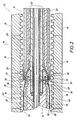
- FIG. 1 shows sections of a device 10 for the production of finned tubes, the device 10 having a spray head 12, a cooling mandrel 14 in the vicinity of the spray head 12 and axially adjacent thereto, and a corrugator 16 with shaped jaws 18.
- the spray head 12 is with a first ring nozzle channel 20 and formed with a second ring nozzle channel 22, which are provided concentrically with each other and open with their nozzle openings 24 and 26 from the end face 28 of the spray head 12 facing the cooling mandrel 14.
- the annular and concentric nozzle openings 24 and 26 thus open out at the same axial height from the spray head 12.
- the first ring nozzle channel 20 is connected to a first extruder (not shown) and the second ring nozzle channel is connected to a second extruder (not shown).
- the spray head 12 is formed with an air supply 30 which leads into the space between the cooling mandrel 14 and that from the nozzle opening 26 of the second ring nozzle channel 22 emerges from the inner layer 32.
- the inner layer 32 consists of a pure plastic material, preferably of polyethylene. After emerging from the nozzle opening 26, the inner layer 32 slides over the smooth outer surface 34 of the cooling mandrel 14.
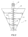
- FIG. 3 shows a tamping device 42 with a conically tapering, funnel-shaped housing 44, in which a stuffing screw device 46 is rotatably mounted.
- the stuffing screw device 46 is connected to a drive motor 48, it has a first conical screw 50 and a second cylindrical screw 52 which extends centrally through the conical first screw 50.
- the tamping device 42 serves to mix the non-sorted, washed and shredded recyclate with a suitable blowing agent and is connected to the first extruder, not shown, belonging to the first ring nozzle channel 20 (see FIGS. 1 and 2).
Landscapes
- Engineering & Computer Science (AREA)
- Mechanical Engineering (AREA)
- Manufacturing & Machinery (AREA)
- Extrusion Moulding Of Plastics Or The Like (AREA)
- Shaping Of Tube Ends By Bending Or Straightening (AREA)
Description
- Die Erfindung betrifft ein Verfahren zur Herstellung von Rippenrohren aus Kunststoff, die eine Innenschicht mit einer glatten Innenrohrfläche und eine Außenschicht mit einer gewölbten Außenrohrfläche aufweisen, wobei das Material für die Innenschicht und das Material für die Außenschicht getrennt voneinander durch einen Spritzkopf in einen Formhohlraum extrudiert wird, der durch einen an den Spritzkopf anschließenden Kühldorn und die Formbacken eines Corrugators festgelegt ist, wobei eine Schicht des Rohres von einem mittels eines chemischen Treibmittels expandierenden Schaum gebildet ist.
- Ein solches Verfahren ist aus der DE 41 28 654 A1 bekannt. Dort wird ein mehrschichtiges Leitungsrohr aus Kunststoff realisiert, das insbes. für Abwässer oder Kabel vorgesehen ist. Das besagte Leitungsrohr weist eine glatte Innenrohrfläche auf und ist mit einem damit verbundenen gewellten und kompakten Außenrohr ausgebildet. Zwischen der Innenrohrfläche und dem Außenrohr ist ein Zwischenrohr vorgesehen, das eine andere Beschaffenheit aufweist als das Außenrohr. Vorzugsweise besteht das Zwischenrohr aus einem Schaummaterial. Dort ist also in jedem Fall ein gewelltes Außenrohr vorhanden, was einen entsprechend ausgebildeten Spritzkopf erforderlich macht. Zur Realisierung des besagten Außenrohres ist es erforderlich, den entsprechenden äußeren kompakten Massestrom für das Außenrohr nach dem Austritt aus dem Spritzkopf mittels Druckluft gegen die Formbacken des Corrugators zu pressen oder mittels eines Vakuums an die Formbacken des Corrugators anzusaugen, wonach eine Entformung und Abkühlung erfolgt. Das bedingt einen nicht zu vernachlässigenden Aufwand. Außerdem handelt es sich dort um ein mindestens dreischichtiges Verbundrohr, bestehend aus dem gewellten Außenrohr, dem glatten Innenrohr und der dazwischen befindlichen Zwischenschicht aus mittels eines chemischen Treibmittels expandiertem Schaum, wobei die Zwischenschicht entweder parallel zum glatten zylindrischen Innenrohr vorgesehen ist oder den Zwischenraum voll ausfüllt. Außenrohr, Zwischenrohr und Innenrohr können aus PVC, PE und/oder PP hergestellt sein. Bspw. können dort alle Rohrschichten aus demselben Material hergestellt sein, wobei das Zwischenrohr eine Schaum- oder eine kompakte Struktur aufweist und aus einem originären Kunststoff oder aus einem Recyclat-Kunststoff bestehen kann.
- Aus dem DE-U-8 509 929 ist ein Kunstoffrohr aus Polyethylen mit einer auf seiner Außenseite koextrudierten und wärmebehandelten Isolierschicht aus einem geschlossenzelligen Polyethylen-Schaum zu entnehmen.
- Aus der US-A-34 96 601 ist ein Stopfwerk bzw. eine Zwangszuführung bekannt, die einem Extruder zugeordnet ist. Diese Zwangszuführung weist ein trichterförmiges Gehäuse auf, in welchem eine Schneckeneinrichtung drehbar gelagert angeordnet ist. Die Schneckeneinrichtung weist eine zylindrische Schnecke sowie ein rahmenförmiges Rührelement auf, das auf der vom Extruder entfernten Oberseite der Schneckeneinrichtung vorgesehen ist.
- Ein Stopfwerk bzw. eine Zwangszuführung, die einem Extruder zugeordnet ist, ist auch aus der US-A-4 958 770 bekannt. Diese Zwangszuführung weist eine zylindrische Schnecke und ein der zylindrischen Schnecke vorgeordnetes Flügelelement auf, wobei die zylindrische Schnecke in einem zylindrischen Förderkanal und das Flügelelement in einem trichterförmigen Gehäuse vorgesehen sind. Der zylindrische Förderkanal befindet sich zwischen dem trichterförmigen Gehäuse und dem Extruder.
- Der Erfindung liegt die Aufgabe zugrunde, ein Verfahren der eingangs genannten Art zu schaffen, wobei es in einfacher Weise möglich ist, Rippenrohre aus nur zwei Schichten vergleichsweise einfach und preisgünstig herzustellen.
- Diese Aufgabe wird dadurch gelöst, daß als Material für die ein geripptes Längsprofil aufweisende Außenschicht ein nicht sortenreines, gewaschenes und zerkleinertes Recyclat verwendet wird, das mit einem geeigneten Treibmittel gemischt durch einen mit einem Stopfwerk bzw. einer anderen Zwangszuführung versehenen ersten Extruder in den Spritzkopf eingebracht wird, aus dem es vom neuwertigen Material für die rohrförmige Innenschicht getrennt und diese konzentrisch umgebend austritt, und das Material für die Außenschicht nach dem Austritt aus dem Spritzkopf im Raum zwischen der Innenschicht und den Formbacken des Corrugators aufschäumt.
- Erfindungsgemäß kommt für die Außenschicht des Rippenrohres also ein nicht sortenreines und nur mechanisch zerkleinertes Recyclat zur Anwendung. Eine Regranulierung kann erfindungsgemäß also entfallen. Bei dem Recyclat kann es sich um ein Gemisch verschiedener Polyolefine wie bspw. LDPE, MDPE, HDPE, PP o.dgl. handeln. Ein weiterer Vorteil besteht darin, daß infolge der erfindungsgemäßen Wiederverwendung des Recyclats Deponiekosten vermieden werden, was unter Umweltgesichtspunkten bedeutsam ist. Bei dem dem gewaschenen und zerkleinerten Recyclat zugemischten Treibmittel kann es sich z.B. um Hydrocerol CF 40E (Warenzeichen der Fa. Boehringer Ingelheim KG.) handeln, das in Form eines weißen Zylindergranulats zur Verfügung steht.
- Da die Formung der Außenschicht durch das dem gewaschenen und zerkleinerten Recyclat zugemischte Treibmittel erfolgt, ist in vorteilhafter Weise zur Formung der besagten Außenschicht keine eigene Luftführung erforderlich, sondern es ist ausreichend, wenn bei der Durchführung des erfindungsgemäßen Verfahrens zwischen der Innenschicht und dem Kühldorn Luft zugeführt wird. Diese Luftzuführung erfolgt zweckmäßigerweise durch den Spritzkopf in Richtung zum Kühldorn.
- Wie bereits erwähnt worden ist, wird für die Außenschicht vorzugsweise ein beliebiges Gemisch gängiger Polyolefine außer PVC verwendet. Für die Innenschicht kommt vorzugsweise ein sortenreines Kunststoffmaterial zur Anwendung. Hierbei handelt es sich bspw. um Polyethylen.
- Der erste Extruder kann zum Mischen von gewaschenem und zerkleinertem, nicht sortenreinem Recyclat mit einem geeigneten Treibmittel mit einem Stopfwerk bzw. einer anderen Zwangszuführung versehen sein. In dem zum ersten Extruder zugehörigen Stopfwerk bzw. der Zwangszuführung erfolgt die Mischung des gewaschenen und zerkleinerten, nicht sortenreinen Recyclats mit dem Treibmittel, wobei durch das Stopfwerk bzw. insbes. im ersten Extruder ein solcher Druck gegeben ist, daß das Treibmittel erst wirksam wird, nachdem der Extrusionsdruck im ersten Extruder bzw. im Spritzkopf stromabwärts nach der Düsenöffnung nicht mehr vorhanden ist, so daß es erst hier zum Aufschäumen des Materials für die Außenschicht kommen kann. Ein Kleben des aufschäumenden Materials für die Außenschicht an der entsprechenden Düsenöffnung wird vermieden, wenn die beiden Ringdüsenkanäle mit ihren Düsenöffnungen aus der dem Kühldorn zugewandten Stirnfläche des Spritzkopfs auf axial gleicher Höhe ausmünden. Hierdurch ist eine reibungslose Produktion der erfindungsgemäßen Rippenrohre möglich.
- Das Stopfwerk bzw. die Zwangszuführung kann ein trichterförmiges Gehäuse aufweisen, in welchem eine Stopfschneckeneinrichtung gelagert ist, die eine erste kegelförmige Schnecke und eine sich durch diese zentral hindurcherstreckende zweite zylindrische Schnecke aufweist.
- Ein ganz erheblicher Vorteil des erfindungsgemäßen Verfahrens besteht darin, daß das zur Anwendung gelangende Recyclat preiswert vorliegt, weil eine Artentrennung des Recyclats erfindungsgemäß nicht erforderlich ist. Wenn man bedenkt, mit welchem Aufwand eine solche Artentrennung der verschiedenen Kunststoffmaterialien bislang durchgeführt wird, kann abgeschätzt werden, welche Vorteile das erfindungsgemäße Verfahren aufweist.
- Eine Vorrichtung zur Durchführung des erfindungsgemäßen Verfahrens ist in der Zeichnung dargestellt und wird nachfolgend beschrieben.Es zeigen:
- Fig. 1
- längsgeschnitten einen Abschnitt der Vorrichtung,
- Fig. 2
- längsgeschnitten eine Darstellung eines Details der Vorrichtung gemäß Fig. 1 in einem größeren Maßstab, und
- Fig. 3
- eine schematische Darstellung eines bei der Vorrichtung zur Anwendung gelangenden Stopfwerks für das nicht sortenreine, gewaschene und zerkleinerte Recyclat und das zugehörige geeignete Treibmittel.
- Fig. 1 zeigt abschnittweise längsgeschnitten eine Vorrichtung 10 zur Herstellung von Rippenrohren, wobei die Vorrichtung 10 einen Spritzkopf 12, einen in der Nachbarschaft des Spritzkopfes 12 und an diesen axial angrenzenden Kühldorn 14 sowie einen Corrugator 16 mit Formbacken 18 aufweist. Der Spritzkopf 12 ist mit einem ersten Ringdüsenkanal 20 und mit einem zweiten Ringdüsenkanal 22 ausgebildet, die zueinander konzentrisch vorgesehen sind und mit ihren Düsenöffnungen 24 und 26 aus der dem Kühldorn 14 zugewandten Stirnfläche 28 des Spritzkopfes 12 ausmünden. Die kreisringförmigen und zueinander konzentrischen Düsenöffnungen 24 und 26 münden also auf axial gleicher Höhe aus dem Spritzkopf 12 aus.
- Der erste Ringdüsenkanal 20 ist mit einem (nicht gezeichneten) ersten Extruder und der zweite Ringdüsenkanal ist mit einem (nicht gezeichneten) zweiten Extruder verbunden.
- Wie insbes. aus Fig. 2, in der gleiche Einzelheiten mit denselben Bezugsziffern bezeichnet sind, wie in Fig. 1, ersichtlich ist, ist der Spritzkopf 12 mit einer Luftzuführung 30 ausgebildet, die in den Raum zwischen dem Kühldorn 14 und der aus der Düsenöffnung 26 des zweiten Ringdüsenkanals 22 austretenden Innenschicht 32 einmündet. Die Innenschicht 32 besteht aus einem sortenreinen Kunststoffmaterial, vorzugsweise aus Polyethylen. Die Innenschicht 32 gleitet nach dem Austreten aus der Düsenöffnung 26 über die glatte Außenoberfläche 34 des Kühldorns 14. Gleichzeitig tritt aus der Düsenöffnung 24 des ersten Ringdüsenkanals 20 das Gemisch aus gewaschenem, zerkleinertem, nicht sortenreinem Recyclat, das mit einem geeigneten Treibmittel gemischt ist, aus und schäumt unmittelbar nach dem Austritt aus der besagten Düsenöffnung 24 auf, wobei es den Zwischenraum 36 zwischen der Innenschicht 32 und den Formbacken 18 des Corrugators 16 vollständig ausfüllt. Erfindungsgemäß ergibt sich also ein zweischichtiges Rippenrohr aus Kunststoff bestehend aus der Innenschicht 32 mit einer glatten, der Außenoberfläche 34 des Kühldorns 14 entsprechenden Innenrohrfläche und einer Außenschicht 38 mit einer geeigneten bzw. gewellten Außenoberfläche 40 entsprechend den Formbacken 18 des Corrugators 16.
- Fig. 3 zeigt ein Stopfwerk 42 mit einem sich konisch verjüngenden, trichterförmigen Gehäuse 44, in dem eine Stopfschneckeneinrichtung 46 drehbar gelagert ist. Die Stopfschneckeneinrichtugn 46 ist mit einem Antriebsmotor 48 verbunden, sie weist eine erste kegelförmige Schnecke 50 und eine zweite zylindrische Schnecke 52 auf, die sich zentral durch die kegelförmige erste Schnecke 50 hindurcherstreckt. Das Stopfwerk 42 dient zur Mischung des nicht sortenreinen, gewaschenen und zerkleinerten Recyclats mit einem geeigneten Treibmittel und ist mit dem zum ersten Ringdüsenkanal 20 (sh. Fig. 1 und 2) zugehörigen, nicht gezeichneten ersten Extruder verbunden.
Claims (4)
- Verfahren zur Herstellung von Rippenrohren aus Kunststoff, die eine Innenschicht (32) mit einer glatten Innenrohrfläche und eine Außenschicht (38) mit einer gewellten Außenoberfläche (40) aufweisen, wobei das Material für die Innenschicht (32) und das Material für die Außenschicht (38) gleichzeitig und voneinander getrennt durch einen Spritzkopf (12) in einen Formhohlraum extrudiert werden, der durch einen an den Spritzkopf (12) anschließenden Kühldorn (14) und die Formbacken (18) eines Corrugators (16) festgelegt ist, wobei eine Schicht des Rohres von einem mittels eines chemischen Treibmittels expandierenden Schaum gebildet ist,
dadurch gekennzeichnet,
daß als Material für die ein geripptes Längsprofil aufweisende Außenschicht (38) ein nicht sortenreines, gewaschenes und zerkleinertes Recyclat verwendet wird, das mit einem geeigneten Treibmittel gemischt durch einen mit einem Stopfwerk (42) bzw. einer anderen Zwangszuführung versehenen ersten Extruder in den Spritzkopf (12) eingebracht wird, aus dem es vom neuwertigen Material für die rohrförmige Innenschicht (32) getrennt und diese konzentrisch umgebend austritt, und das Material für die Außenschicht (38) nach dem Austritt aus dem Spritzkopf (12) im Raum zwischen der Innenschicht (32) und den Formbacken (18) des Corrugators aufschäumt. - Verfahren nach Anspruch 1,
dadurch gekennzeichnet,
daß zwischen der Innenschicht (32) und dem Kühldorn (14) Luft zugeführt wird. - Verfahren nach Anspruch 1,
dadurch gekennzeichnet,
daß für die Außenschicht (38) ein beliebiges Gemisch gängiger Polyolefine außer PVC verwendet wird. - Verfahren nach Anspruch 1,
dadurch gekennzeichnet,
daß für die Innenschicht (32) ein sortenreines Kunststoffmaterial verwendet wird.
Applications Claiming Priority (2)
| Application Number | Priority Date | Filing Date | Title |
|---|---|---|---|
| DE4325021A DE4325021C1 (de) | 1993-07-26 | 1993-07-26 | Verfahren und Vorrichtung zur Herstellung von Rippenrohren aus Kunststoff |
| DE4325021 | 1993-07-26 |
Publications (3)
| Publication Number | Publication Date |
|---|---|
| EP0636466A2 EP0636466A2 (de) | 1995-02-01 |
| EP0636466A3 EP0636466A3 (de) | 1995-03-29 |
| EP0636466B1 true EP0636466B1 (de) | 1997-01-22 |
Family
ID=6493717
Family Applications (1)
| Application Number | Title | Priority Date | Filing Date |
|---|---|---|---|
| EP94111095A Expired - Lifetime EP0636466B1 (de) | 1993-07-26 | 1994-07-16 | Verfahren zur Herstellung von Rippenrohren aus Kunststoff |
Country Status (3)
| Country | Link |
|---|---|
| EP (1) | EP0636466B1 (de) |
| DE (2) | DE4325021C1 (de) |
| ES (1) | ES2098830T3 (de) |
Families Citing this family (7)
| Publication number | Priority date | Publication date | Assignee | Title |
|---|---|---|---|---|
| DE19604311A1 (de) * | 1996-02-07 | 1997-08-14 | Ralph Peter Dr Ing Hegler | Verbundrohr mit Muffe und Verfahren zu seiner Herstellung |
| DE29616289U1 (de) * | 1996-09-19 | 1996-11-28 | Unicor Rohrsysteme GmbH, 97437 Haßfurt | Mehrschichtiges Kunststoffrohr |
| DE19640928A1 (de) * | 1996-10-04 | 1998-04-09 | Ralph Peter Dr Ing Hegler | Vorrichtung zur Herstellung von Kunststoff-Verbund-Rohren |
| DE19827435C2 (de) * | 1998-06-19 | 2000-06-08 | Kirchner Fraenk Rohr | Rohrförmiger Hohlkörper mit Wellungen mit einer Verschlußeinrichtung sowie Verfahren zur Herstellung eines deratigen rohrförmigen Hohlkörpers |
| GB0012281D0 (en) * | 2000-05-22 | 2000-07-12 | Uponor Ltd | Recycled pipe |
| DE10117126C1 (de) * | 2001-04-06 | 2002-08-01 | Unicor Rohrsysteme Gmbh | Vorrichtung zur Herstellung von Doppelwand-Wellrohren |
| CN113459454B (zh) * | 2021-06-09 | 2022-03-11 | 安徽森泰木塑科技地板有限公司 | 增强发泡地板、其制备用的挤出模具和设备组 |
Family Cites Families (10)
| Publication number | Priority date | Publication date | Assignee | Title |
|---|---|---|---|---|
| US3496601A (en) * | 1967-04-14 | 1970-02-24 | Midland Ross Corp | Feeder for auger-type extruder |
| BE723947A (de) * | 1967-11-16 | 1969-05-14 | ||
| DE2042031A1 (de) * | 1970-08-25 | 1972-05-31 | Reifenhaeuser Kg | Verfahren und Vorrichtung zur Herstellung von Wellrohren aus thermoplastischem Kunststoff |
| AT352386B (de) * | 1972-10-19 | 1979-09-10 | Kagerer Eisen Kunststoff | Verfahren und vorrichtung zum kontinuierlichen herstellen von aus mindestens zwei schichten bestehenden kunststoffrohren mit querprofilierungen |
| DE3513708C2 (de) * | 1985-04-12 | 1994-04-21 | Drossbach Gmbh & Co Kg | Extrusionskopf zur Herstellung doppelwandiger Kunststoffrohre mit zylindrischem Innenrohr und quergewelltem Außenrohr |
| DE8509929U1 (de) * | 1985-04-03 | 1986-07-31 | Hewing GmbH & Co, 4434 Ochtrup | Isoliertes Kunststoffrohr |
| US4958770A (en) * | 1989-05-03 | 1990-09-25 | Prescision Porous Pipe, Inc. | Process for making uniform porosity flexible irrigation pipe |
| DE4128654C2 (de) * | 1991-08-29 | 1995-05-18 | Wolfgang Mayer | Mehrschichtiges Leitungsrohr aus Kunststoff und Verfahren zu dessen Herstellung |
| CA2223520C (en) * | 1991-11-22 | 2001-02-06 | Manfred A. A. Lupke | Method and apparatus of forming profiled pipe |
| DE4204759C1 (de) * | 1992-02-18 | 1992-12-03 | Friedrich Theysohn Gmbh, 3012 Langenhagen, De |
-
1993
- 1993-07-26 DE DE4325021A patent/DE4325021C1/de not_active Expired - Fee Related
-
1994
- 1994-07-16 DE DE59401640T patent/DE59401640D1/de not_active Expired - Fee Related
- 1994-07-16 EP EP94111095A patent/EP0636466B1/de not_active Expired - Lifetime
- 1994-07-16 ES ES94111095T patent/ES2098830T3/es not_active Expired - Lifetime
Also Published As
| Publication number | Publication date |
|---|---|
| DE59401640D1 (de) | 1997-03-06 |
| DE4325021C1 (de) | 1995-03-02 |
| EP0636466A3 (de) | 1995-03-29 |
| ES2098830T3 (es) | 1997-05-01 |
| EP0636466A2 (de) | 1995-02-01 |
Similar Documents
| Publication | Publication Date | Title |
|---|---|---|
| EP0995579B1 (de) | Verfahren zur fortlaufenden Herstellung eines Verbundrohres mit einer Rohr-Muffe und Vorrichtung zur Durchführung des Verfahrens | |
| DE1629364B2 (de) | Verfahren und vorrichtung zum extrudieren einer aus thermoplastischen kunststoffen bestehenden verbundbahn | |
| DE69629491T2 (de) | Verfahren zum herstellen von homogenen materialien mit einem extruder, und extruder | |
| DE69707763T2 (de) | Verfahren und Vorrichtung zum Herstellen von Rohren aus wiederverwendetem thermoplastischem Kunststoff | |
| DE4128654C2 (de) | Mehrschichtiges Leitungsrohr aus Kunststoff und Verfahren zu dessen Herstellung | |
| DE4325021C1 (de) | Verfahren und Vorrichtung zur Herstellung von Rippenrohren aus Kunststoff | |
| EP3872382B1 (de) | Thermisch gedämmtes leitungsrohr | |
| DE3044535A1 (de) | Verfahren und vorrichtung zur herstellung mehrschichtiger kunststoffprofile, insbesondere kunststoffrohre | |
| DE29706045U1 (de) | Mehrschichtiges Kunststoff-Rohr | |
| DE10046454B4 (de) | Verfahren zum Durchspülen polymer beziehungsweise kunststoffschmelzeführender Teile von Folienextrusionanlagen | |
| DE19832469A1 (de) | Verfahren zum Herstellen einer Abdeckhaut für die Instrumententafel eines Kraftfahrzeuges | |
| DE102018108308A1 (de) | Mehrschichtige blasgeformte Extrusion | |
| CH718489B1 (de) | Thermisch gedämmtes Rohr. | |
| EP0879142B1 (de) | Mehrschichtiges kunststoffrohr | |
| EP2225083B1 (de) | Verfahren zur herstellung eines vorformlings sowie die verwendung des verfahrens | |
| DE3109216C2 (de) | Verfahren und Vorrichtung zum Ummanteln eines Stahlrohres | |
| DE4204759C1 (de) | ||
| CH687449A5 (de) | Verfahren zum Strangpressen von Hohlprofilen. | |
| DE2440193B2 (de) | Vorrichtung zum Spritzgießen von Formkörpern aus thermoplastischem Kunststoff | |
| DE20108412U1 (de) | Vorrichtung zur Herstellung eines rohrartigen Elements aus Silikongummi mit Textilverstärkung und damit hergestelltes rohrartiges Element | |
| DE10237051A1 (de) | Verfahren und Vorrichtung zur Herstellung blasgeformter Hohlkörper aus thermoplastischen Kunststoffen | |
| EP1985433B1 (de) | Verfahren zur Herstellung von rohrförmigen Kunststoffprofilen | |
| DE4430038A1 (de) | Verfahren zur Herstellung doppelwandiger Rohre aus Kunststoff | |
| DE19851076A1 (de) | Verfahren und Vorrichtung zur Herstellung eines Zusatzteils für ein technisches Formteil | |
| EP2236267A1 (de) | Verfahren und Vorrichtung zur Herstellung eines Kunststoffbauteils sowie Kunststoffbauteil |
Legal Events
| Date | Code | Title | Description |
|---|---|---|---|
| PUAI | Public reference made under article 153(3) epc to a published international application that has entered the european phase |
Free format text: ORIGINAL CODE: 0009012 |
|
| AK | Designated contracting states |
Kind code of ref document: A2 Designated state(s): DE ES FR GB IT SE |
|
| PUAL | Search report despatched |
Free format text: ORIGINAL CODE: 0009013 |
|
| AK | Designated contracting states |
Kind code of ref document: A3 Designated state(s): DE ES FR GB IT SE |
|
| 17P | Request for examination filed |
Effective date: 19950310 |
|
| 17Q | First examination report despatched |
Effective date: 19951207 |
|
| GRAG | Despatch of communication of intention to grant |
Free format text: ORIGINAL CODE: EPIDOS AGRA |
|
| GRAH | Despatch of communication of intention to grant a patent |
Free format text: ORIGINAL CODE: EPIDOS IGRA |
|
| GRAH | Despatch of communication of intention to grant a patent |
Free format text: ORIGINAL CODE: EPIDOS IGRA |
|
| GRAA | (expected) grant |
Free format text: ORIGINAL CODE: 0009210 |
|
| AK | Designated contracting states |
Kind code of ref document: B1 Designated state(s): DE ES FR GB IT SE |
|
| GBT | Gb: translation of ep patent filed (gb section 77(6)(a)/1977) |
Effective date: 19970206 |
|
| REF | Corresponds to: |
Ref document number: 59401640 Country of ref document: DE Date of ref document: 19970306 |
|
| ET | Fr: translation filed | ||
| ITF | It: translation for a ep patent filed | ||
| REG | Reference to a national code |
Ref country code: ES Ref legal event code: FG2A Ref document number: 2098830 Country of ref document: ES Kind code of ref document: T3 |
|
| PLBE | No opposition filed within time limit |
Free format text: ORIGINAL CODE: 0009261 |
|
| STAA | Information on the status of an ep patent application or granted ep patent |
Free format text: STATUS: NO OPPOSITION FILED WITHIN TIME LIMIT |
|
| 26N | No opposition filed | ||
| REG | Reference to a national code |
Ref country code: GB Ref legal event code: IF02 |
|
| PGFP | Annual fee paid to national office [announced via postgrant information from national office to epo] |
Ref country code: GB Payment date: 20020625 Year of fee payment: 9 |
|
| PGFP | Annual fee paid to national office [announced via postgrant information from national office to epo] |
Ref country code: DE Payment date: 20020715 Year of fee payment: 9 |
|
| PGFP | Annual fee paid to national office [announced via postgrant information from national office to epo] |
Ref country code: FR Payment date: 20020717 Year of fee payment: 9 |
|
| PGFP | Annual fee paid to national office [announced via postgrant information from national office to epo] |
Ref country code: SE Payment date: 20020723 Year of fee payment: 9 |
|
| PGFP | Annual fee paid to national office [announced via postgrant information from national office to epo] |
Ref country code: ES Payment date: 20020724 Year of fee payment: 9 |
|
| PG25 | Lapsed in a contracting state [announced via postgrant information from national office to epo] |
Ref country code: GB Free format text: LAPSE BECAUSE OF NON-PAYMENT OF DUE FEES Effective date: 20030716 |
|
| PG25 | Lapsed in a contracting state [announced via postgrant information from national office to epo] |
Ref country code: SE Free format text: LAPSE BECAUSE OF NON-PAYMENT OF DUE FEES Effective date: 20030717 Ref country code: ES Free format text: LAPSE BECAUSE OF NON-PAYMENT OF DUE FEES Effective date: 20030717 |
|
| PG25 | Lapsed in a contracting state [announced via postgrant information from national office to epo] |
Ref country code: DE Free format text: LAPSE BECAUSE OF NON-PAYMENT OF DUE FEES Effective date: 20040203 |
|
| EUG | Se: european patent has lapsed | ||
| GBPC | Gb: european patent ceased through non-payment of renewal fee |
Effective date: 20030716 |
|
| PG25 | Lapsed in a contracting state [announced via postgrant information from national office to epo] |
Ref country code: FR Free format text: LAPSE BECAUSE OF NON-PAYMENT OF DUE FEES Effective date: 20040331 |
|
| REG | Reference to a national code |
Ref country code: FR Ref legal event code: ST |
|
| REG | Reference to a national code |
Ref country code: ES Ref legal event code: FD2A Effective date: 20030717 |
|
| PG25 | Lapsed in a contracting state [announced via postgrant information from national office to epo] |
Ref country code: IT Free format text: LAPSE BECAUSE OF NON-PAYMENT OF DUE FEES Effective date: 20050716 |