EP0636034B1 - Liquid delivery apparatus - Google Patents
Liquid delivery apparatus Download PDFInfo
- Publication number
- EP0636034B1 EP0636034B1 EP93912173A EP93912173A EP0636034B1 EP 0636034 B1 EP0636034 B1 EP 0636034B1 EP 93912173 A EP93912173 A EP 93912173A EP 93912173 A EP93912173 A EP 93912173A EP 0636034 B1 EP0636034 B1 EP 0636034B1
- Authority
- EP
- European Patent Office
- Prior art keywords
- support
- distendable
- liquid
- membrane
- outlet
- Prior art date
- Legal status (The legal status is an assumption and is not a legal conclusion. Google has not performed a legal analysis and makes no representation as to the accuracy of the status listed.)
- Expired - Lifetime
Links
Images


Classifications
-
- A—HUMAN NECESSITIES
- A61—MEDICAL OR VETERINARY SCIENCE; HYGIENE
- A61M—DEVICES FOR INTRODUCING MEDIA INTO, OR ONTO, THE BODY; DEVICES FOR TRANSDUCING BODY MEDIA OR FOR TAKING MEDIA FROM THE BODY; DEVICES FOR PRODUCING OR ENDING SLEEP OR STUPOR
- A61M5/00—Devices for bringing media into the body in a subcutaneous, intra-vascular or intramuscular way; Accessories therefor, e.g. filling or cleaning devices, arm-rests
- A61M5/14—Infusion devices, e.g. infusing by gravity; Blood infusion; Accessories therefor
- A61M5/142—Pressure infusion, e.g. using pumps
- A61M5/145—Pressure infusion, e.g. using pumps using pressurised reservoirs, e.g. pressurised by means of pistons
- A61M5/148—Pressure infusion, e.g. using pumps using pressurised reservoirs, e.g. pressurised by means of pistons flexible, e.g. independent bags
- A61M5/152—Pressure infusion, e.g. using pumps using pressurised reservoirs, e.g. pressurised by means of pistons flexible, e.g. independent bags pressurised by contraction of elastic reservoirs
Definitions
- the present invention relates to a liquid delivery apparatus as defined in the preamble of claim 1. More particularly, the invention concerns an apparatus for enteral feeding applications.
- enteral feeding becomes necessary.
- Enteral nutrition, or tube feeding is typically accomplished by nasogastric administration or by direct delivery of liquids to the stomach via a surgically implanted feeding tube.
- Parastalic pumps are currently used for nasogastric feeding when gravity flow from an elevated container is insufficient to instill flow or when an exact amount of regulated feeding is necessary. Such devices are cumbersome to use and at times have proven unreliable.
- the apparatus of the present invention overcomes the draw-backs of prior art enteral feeding systems by providing a self-contained apparatus which includes an internal energy source that automatically expels prepackaged nutritional liquids from a sealed aseptic container at a desired uniform rate.
- Aseptic packaging is, of course, not new. Such packaging is being used more and more in the food industry for packaging fruit juice, milk products and the like. Additionally, some use of aseptic packaging has been made in the medical field for packaging medical solutions.
- the packaged, aseptically filled liquid is a food product, such as fruit juice
- the sealed package is typically punctured at a specific site location and the juice is withdrawn through a straw.
- the packaged liquid is a medical solution
- the package is typically opened, mixed with other components when required and emptied into a traditional, wide-mouth flexible bag solution container for enteral delivery by conventional gravity means and parastalic pump.
- U.S. Patent No. 4,826,500 issued to Rantsola a system for the enteral delivery of a medical solution directly from an aseptic container is there described.
- the solution is passed from a container through an elongated giving set and metering system into a nasal tube.
- the container is an aseptic carton having penetrable side walls, with the giving set being provided with a fitting having a fluid passage extending therethrough.
- the fitting terminates at a carton cooperating portion which includes a first portion for penetrating the carton side walls to form an orifice therein, the orifice establishing fluid communication between the carton interior and the fitting fluid passage, and a second portion for engaging the carton side wall to maintain cooperation between the carton and fitting.
- the disadvantageous current practice of preparing the dry nutrient composition and mixing it with sterile water at the point of use is avoided.
- the current practice of preparing the dry nutrient composition and mixing with sterile water at point of use has many obvious disadvantages.
- the use of this two-step method of treatment preparation has, in part, been driven by the problems resulting from combined solution sterilization, including chemical reactivity of certain nutrient materials under autoclave conditions because of the flexible bag.
- Prior art practices also typically employ intermittent feeding of the patient. Recent clinical practice now favors continuous feeding rather than intermittent feeding in most cases.
- certain drugs, minerals, nutrients and the like are aseptically sealed in a multi-barrier layer, oxygen impermeable, moisture-proof, microorganism-impermeable aseptic dispenser for automatic, on-demand continuous delivery to the patient without the required use of a parastalic pump or external energy sources of any kind.
- U.S. Patent No. 4, 953, 753 an apparatus for dispensing fluids is disclosed.
- This apparatus generates its own positive pressure from a prestressed elastomeric material.
- the dispenser includes a resilient bladder of generally tubular shape having an open end into which an internal prestressing membrane is inserted to prestress the bladder in both the radial and axial directions.
- an apparatus as defined in the preamble of claim 1 is known by this U.S. patent.
- an object of the invention to provide a system of the aforementioned character in which an integral, inherently sterile, flat film energy source is contained within the aseptic package for automatically delivering on demand the premixed solution contained within the package to the patient at a precisely controlled rate.
- Another object of the invention is to provide an aseptic carton having a non-permeable oxygen barrier with a penetrating portion for sealable penetration by a fitting having a fluid passageway therethrough in communication with a giving set.
- Another object of the invention is to provide a carton as described in the preceding paragraph in which provision is made for ingress of make-up air so that an even outflow of solution to the patient is precisely maintained.
- Another object of the invention is to provide a carton which utilizes a paper-board barrier laminated structure that maintains an isolated gas environment within the container.
- Still another object of the invention is to provide a system of the class described in which the aseptic container and flat film integral energy source, or elastomeric membrane, can be economically mass produced at low cost to permit the discard of the assembly after use.
- the liquid delivery apparatus of the present invention comprises a body made up of cooperating first and second portions 12a and 12b respectively.
- each body portion 12a and 12b includes internal walls defining cavities 14a and 14b respectively with each cavity being circumscribed by an edge 16a and 16b respectively.
- Each body portion is also provided at either end with semi-circular shaped, indexable openings generally designated by the numerals 18 and 20.
- a first distendable membrane 22 is provided with an edge portion 22a which is disposed in engagement with edge portion 16a of first body portion 12a.
- a second distendable membrane 24 having an edge portion 24a is disposed in engagement with edge portion 16b of second body portion 12b.
- Each of the distendable membranes 22 and 24, the unique character of which will presently be described, includes a central portion 22b and 24b respectively which spans the cavity of the body portion with which the membrane is associated ( Figure 5).
- a rigid support, or ullage member 26 Disposed between distendable membranes 22 and 24 is a rigid support, or ullage member 26.
- Support member 26 which can be constructed from any suitable plastic such as polypropylene, polystyrene, polyethylene, or polycarbonate, is provided with a longitudinally extending fluid passageway 30 which is in communication at one end with a fluid inlet port 32 of an inlet port assembly 33 and is in communication at its opposite end with a fluid outlet port 34 of an outlet port assembly 35.
- Fluid inlet port assembly 33 includes an inlet adapter 36 having a flange portion 36a and a neck portion 36b which is closely received within apertures 18 provided in body portions 12a and 12b.
- outlet port 34 includes a flange portion 34a and a neck portion 34b which portion is closely received within apertures 20 provided in body portions 12a and 12b. It is to be noted that body portions 12a and 12b are also provided with semicircular shaped recessed portions 39 which are adapted to closely receive flange portion 38a of outlet port adapter 38 which in this form of the invention comprises a port of the vent means for permitting the flow of gases between atmosphere and the interior of the liquid delivery apparatus.
- a fluid delivery means which is in communication with the fluid outlet port of the apparatus.
- the fluid delivery means functions to deliver fluid to the patient.
- This fluid delivery means is shown in Figure 2 as comprising a delivery spike assembly 40, which is adapted to cooperate with the fluid outlet port assembly 35.
- body portions 12a and 12b are encapsulated by oxygen non-permeable encapsulating barrier means shown here as thin layers of material 41 and 42 sealably surrounding body portions 12a and 12b ( Figure 9).
- This sealing material and the manner in which it is applied will be discussed hereinafter.
- a check valve assembly comprising a duckbill-type check valve 44 of conventional construction which is held in position within neck portion 36b by an internally threaded retainer ring 46 which is received over flange portion 36a.
- a threaded closure plug 48 is threadably received within retainer ring 46 in the manner best seen in Figure 4.
- Duckbill valve 44 includes a yieldably deformable "bill" 44a which functions in the traditional manner illustrated in Figures 6 and 7, permitting fluid to flow inwardly in the direction of the arrows designated by the numerals 50 in Figure 6, but blocking fluid flow in the opposite direction in the manner shown in Figure 7. It is to be understood that various types of check valves of a character well known to those skilled in the art can be used in place of the duckbill valve 44.
- Body portions, or structural support members 12a and 12b can be constructed of any suitable gas permeable, porous material such as Polypropylene (PP), Ultra High Molecular Weight Polyethylene (UHMWPE), High Density Polyethylene (HDPE), Polyvinylidene Fluoride (PVDF), Ethyle-vinyl Acetate (EVA), Styrene Acrylonitrile (SAN), Polytetrafluroethylene (PTFE) and porous cellulose acetate.
- PP Polypropylene
- UHMWPE Ultra High Molecular Weight Polyethylene
- HDPE High Density Polyethylene
- PVDF Polyvinylidene Fluoride
- EVA Ethyle-vinyl Acetate
- SAN Styrene Acrylonitrile
- PTFE Polytetrafluroethylene
- porous cellulose acetate porous cellulose acetate.
- a suitable source of these materials is Porex Technologies of Fairburn, Georgia. However, practice has shown that any porous plastic material including an open cell,
- membranes 22 and 24 can be single layers or laminates and can be manufactured from several alternate materials including rubber, plastics and other thermo-plastic elastomers. These include latex, rubber polyisoprene, butyl rubber, nytrial rubber, other homopolymer, copolymers, mechanical poly blends and interpenetrating polymer networks. Examples of materials found particularly well suited for the construction of the high gas permeable membranes include silicon polymers which are castable into thin film membranes having high gas permeability. Depending upon the fluid to be dispensed from the apparatus, other materials of choice for fabricating the membranes include polyurethane-polysiloxane, copolymers, blends and IPNs (interpenetrating polymer network materials).
- low gas permeable membranes such as floro-silicons and floro-elastomers may be desirable.
- Manufacturers of materials suitable for use in the construction of the distendable membranes 22 and 24 include Dow Chemical, 3M Company, General Electric, Mobay Chemical, Shell Oil Corporation, DuPont, and Union Carbide Corporation.
- vent means of the invention is adapted to provide for make-up air during liquid delivery so that an even outflow of solution from the apparatus is obtained.
- flange 38a of outlet adapter 38 is provided with circumferentially spaced apertures 38c which permit free flow of air toward fluid chambers 14a and 14b in the manner shown by the arrows 51 in Figure 7.
- an oxygen impermeable sterile barrier patch 53 is removably affixed to flange 34 so as to cover apertures 38c.
- the encapsulating means shown here as an outer barrier which surrounds the body portions 12a and 12b is perforated in the area of the apertures 38c provided in the flange 38. These apertures in the outer barrier permit air from atmosphere to flow into the porous body portions 12a and 12b in the manner shown by the arrows in Figure 7 and designated by the numeral 51.
- the encapsulating means or outer barrier in the embodiment of the invention there shown comprises an outer paper wrap 42 covering an inner metalized wrap or encapsulation material 41.
- the outer barrier or encapsulating means can take several forms so long as it produces an oxygen impermeable, anti-microbial leak-free aseptic container.
- the encapsulation means can comprise a barrier laminate structure which is made up of a plurality of specific high-strength polymer resin layers which effectively prevent formation of pin holes or cracking of oxygen barrier layers during package formation.
- One type of oxygen impermeable, leak-free container material is disclosed in U.S. Patent No. 4,983,431 issued to Gibbons et al.
- outlet port 34 is initially closed by a frangible diaphragm 56 which form an integral part of the outlet adapter 38.
- neck 38b of outlet adapter 38 is internally threaded with threads 58 which are adapted to threadably receive external threads 60 provided on the delivery spike assembly 40.
- Delivery spike assembly 40 includes an outwardly extending, generally cylindrically shaped portion 40a that terminates in a sharp spike or point 40b. point 40b is adapted to pierce frangible membrane 56 when the delivery spike is threadably connected with the outlet port assembly 34 in the manner illustrated in Figure 7.
- An elastomeric O ring 64 is received within a groove 65 provided in cylindrical portion 40a and sealably engages the internal walls of neck 38b in the manner shown in Figure 7. This prevents leakage of fluid from the pressurized container past the delivery spike and to the outside of the container.
- a tubular conduit C that communicates with an external flow rate control means shown here as a cylindrical housing 65 having contained therewithin a porous mass of material 67 such as porous TEFLON®, through which the discharging liquid must flow.
- Flow rate can be precisely controlled by proper selection of the material 67 in a manner well known to those skilled in the art.
- plug 48 is first removed and threadably inserted in its place is a fill tube 66 having a threaded fitting 68 which is receivable within retaining ring 46 ( Figure 6).
- the nutrient solution to be delivered to the patient is introduced through the check valve 44.
- the fluid being introduced will impinge upon membranes 22 and 24 causing them to distend from a first at rest position shown in Figures 4 and 5, wherein the central portions of the membranes are in proximity with support member 26, to a second distended position shown in Figures 6 and 7, wherein the central portions of the membranes are in proximity with the internal walls defining cavities 14a and 14b.
- gas in the solution being introduced into the carton can pass through the membranes 22 and 24 and migrate to porous foam blocks 12a and 12b with subsequent venting at time of use to atmosphere through orifices 38c. It is to be understood that distention of the membranes from the first to the second position creates internal stresses of predetermined direction and magnitude in the specifically tailored thin films of elastomeric membranes which tend to uniformly return them to their original, non-distended position shown in Figures 4 and 5.
- the retaining ring 46 and check valve assembly 44 can be recessed into body portions 12a and 12b so that after aseptic filling of the carton is complete, the outer most barrier of the encapsulation means can be folded over the check valve assembly in a manner to effectively seal it relative to atmosphere.
- FIG. 10a, 11 and 12 another form of the liquid delivery apparatus of the present invention is there illustrated.
- This form of the invention is similar in most respects to the form of the invention described in the preceding paragraphs. Accordingly like numbers have been used to identify like components.
- the principal differences between this latter embodiment of the invention and the former embodiment resides in the provision of a differently configured check valve assembly 80 as well as differently configured distendable membrane assemblies 84.
- the check valve assembly of this latter embodiment of the invention comprises an outer sleeve 86 which is receivable within fluid inlet 32.
- a flange 88 which is bondably interconnected with flange 36a of the inlet adapter 36.
- the check valve member of this alternate form of the invention comprises a generally cylindrically shaped member 90 having a body portion 92 and a reduced diameter neck portion 94. A shoulder 96 is formed at the junction of neck portion 94 and body portion 92.
- Check valve member 90 is reciprocally movable within sleeve 86 from an outward sealing position wherein shoulder 96 sealably engages an internal shoulder provided in member 88 to a retracted position wherein liquid will be permitted to flow through inlet port 32 and into pressural communication with the distendable membrane assemblies 84 of this form of the invention. It should be understood that once the device is pressurized by the filling of the nutritional fluids, the check valve member 90 will be urged into a sealing forward position blocking liquid flow outwardly through the inlet port 32. However, during the filling operation, the check valve member is movable rearwardly of sleeve 86 so as to permit fluid flow through a plurality of circumferentially spaced fluid flow passageways 97 provided in check valve member 90 ( Figure 11).
- each of the distendable membranes of this later form of the invention comprises a laminate structure made up of a plurality of layers of elastomeric material 84a, 84b and 84c.
- This assemblage functions in much the same way as earlier described distendable membranes 22 and 24.
- the elastic characteristic of the stored energy means can be precisely tailored and can be uniquely constructed to function not only as a fluid driving medium but also as a gas permeability valve.
- the selective arrangement of the different films that make up the stored energy means, each with its own ascending permeability constant, will dictate the direction of flow of various gases and vapors. Vapors contained within the solution introduced into the device can pass through the stored energy means in one direction while external gases will be precluded from negative migration into the reservoir.
- the solution contained within the device is delivered to the patient through the delivery spike assembly 40 in the same manner as was described in the discussion of the previous embodiment. Similarly, make-up air is supplied by the vent means through apertures 38(c) in the manner discussed in the preceding paragraphs.
- the liquid delivery apparatus of this latest form of the invention comprises a base assembly 100, a carton-like body 102 within which the base assembly is encapsulated and a distendable membrane assembly 104 which overlays base assembly 100.
- Base assembly 100 has a fluid inlet and a fluid outlet 106 and 108 respectively and includes a central, convex portion 110 which is circumscribed by an edge portion 112.
- Distendable membrane assembly 104 also includes a central portion 114 which is circumscribed by upper and lower edge portions 116 and 118 respectively.
- distendable membrane assembly 104 can be made up of at least two, but preferably a plurality of thin film distendable membranes 104a, 104b and 104c.
- layer 104a which is distal to the reservoir comprises a thin film elastomer of a first thickness and a first permeability.
- layer 104c which is proximal to the reservoir comprises a thin elastomer film of a second thickness and a second permeability.
- This film is uniquely selected to be compatible in all respects with the fluid continued within the reservoir.
- Lay 104b can be of yet another thickness and permeability and, if desired can also have different perm-select characteristics. As previously described, the selective arrangement of the different films, each with its own individual permeability constants in ascending order, will dictate the direction of flow of selected gases and vapors through the stored energy means.
- body assembly 102 includes an inner barrier member 119 having internal surfaces 120 which define a cavity or fluid reservoir 122.
- Barrier member 119 is provided with end flaps (not shown) which can be folded over into the position shown in the drawings after the reservoir 122 is filled in the manner presently to be described.
- Distendable membrane assembly 104 is distendable from a first position wherein the central portion 114 thereof is in close proximity with the central portion 110 of base assembly 100 to a second distended position wherein central portion 114 is in close proximity with the upper internal walls 120a of body assembly or carton 102.
- the membrane assembly also moves into close proximity with the internal surfaces 120b of walls 120 of the carton ( Figure 16) and with the internal surfaces of end walls 120c ( Figure 15.)
- the distendable membrane assembly 104 is distended from the first to the second position, internal stresses are developed within the membrane which tend to uniformly return it toward its first position in close proximity with the central portion 110 of base assembly 100.
- base assembly 100 is provided with a longitudinally extending flow channel 130 which communicates with an internal longitudinally extending flow passageway 132 that extends between and interconnects together inlet 106 and outlet 108.
- flow passageway 132 is formed internally of a semitubular shaped, longitudinally extending protuberance 133 formed integrally with base assembly 100.
- check valve assembly Disposed proximate the inlet portion of fluid passageway 132 is a check valve assembly generally designated by the numeral 134.
- a similar check valve 136 is disposed proximate the outlet portion of fluid passageway 132.
- inlet check valve 134 is receivable within a cylindrically shaped retaining member 140 which is receivably within an enlarged diameter portion 133a of protuberance 133.
- Member 140 has an internal shoulder 142 adapted to engage an external shoulder 144 formed on check valve 134.
- Check valve 136 which is positioned proximate the outlet of fluid passageway 132 is held in position within the fluid passageway by a retainer member 146 which is disposed within passageway 132 in engagement with an internally threaded outlet receptacle 147.
- Outlet receptacle 147 which comprises a part of the vent means of the invention, includes a tubular body portion 147a and flange portion 148 having a plurality of circumferentially spaced apertures 150 ( Figure 13).
- the reduced diameter portion 136a of check valve 136 is movably receivable within a bore provided in retainer member 146. With the shoulder 136b of the check valve 136 in sealable engagement member 146 fluid flow through passageway 132 in a direction toward outlet 108 is effectively blocked.
- a flow rate control means shown here as an elongated, generally cylindrically shaped porous filter member 160.
- Member 160 can be constructed of any inert porous material such as a ceramic or porous plactic, fluid permeable material and can be tailored to provide a precise rate of fluid flow through passageway 132 in a manner well known to those skilled in the art.
- tubular body portion 147a of receptacle 147 is positioned within an enlarged diameter portion 132a of flow passageway 132 with flange 148 of member 147 positioned against base assembly 100.
- a hydrophobic filter vent means for venting air but not moisture is here shown as disk shaped member 166 which is appropriately bonded to the interior surfaces of flange 148 of member 147 in the manner shown in Figure 18.
- a material such as hydrophobic PTFE, polytetrafluoroethylene incorporating laminated polypropylene or hydrophobic acrylic copolymer supported on nylon nonwoven substrates is suitable for the construction of member 166.
- chamber or reservoir 122 is filled with the selected feeding solution by inserting an appropriate filling conduit into the inlet portion of the device (not shown).
- the filling conduit is adapted to move check valve 134 inwardly permitting the feeding solution to flow into passageway 132 and then outwardly of channel 130 where it impinges on membrane assembly 104 with sufficient pressure to distend it in to the position shown in Figures 15 and 16.
- a retainer disk 162 is positioned over the inlet or filling port 106 and the end flaps of barrier member 119 and folded over to hold disk 162 as well as outlet receptacle 147 in position.
- an outer barrier layer 167 ( Figures 13 and 20) is emplaced over the entire assemblage so as to completely encapsulate it within a sealed oxygen impermeable, antimicrobial, leak-free aseptic container of the character previously described herein.
- a disk shaped metalized seal 168 is positioned over the outer barrier in the proximity of the vent means or flange 148 of outlet receptacle 147.
- delivery spike 170 of a construction similar to delivery spike 140 of the earlier described embodiments.
- delivery spike 170 comprises a finger grip portion 172, a flange portion 174 and an externally threaded neck portion 176.
- a plurality of circumferentially spaced, outwardly extending pointed protuberances 177 are provided on flange portion 174.
- protuberances 177 will pierce metalized seal 168 and will extend into vent apertures 150 thereby creating openings which permit make-up air to flow into the device as the feeding solution is introduced into the patient.
Description
- The present invention relates to a liquid delivery apparatus as defined in the preamble of claim 1. More particularly, the invention concerns an apparatus for enteral feeding applications.
- When patients are comatose, or for some reason are unable to take nourishment by mouth, enteral feeding becomes necessary. Enteral nutrition, or tube feeding, is typically accomplished by nasogastric administration or by direct delivery of liquids to the stomach via a surgically implanted feeding tube. Parastalic pumps are currently used for nasogastric feeding when gravity flow from an elevated container is insufficient to instill flow or when an exact amount of regulated feeding is necessary. Such devices are cumbersome to use and at times have proven unreliable.
- The apparatus of the present invention overcomes the draw-backs of prior art enteral feeding systems by providing a self-contained apparatus which includes an internal energy source that automatically expels prepackaged nutritional liquids from a sealed aseptic container at a desired uniform rate.
- Aseptic packaging is, of course, not new. Such packaging is being used more and more in the food industry for packaging fruit juice, milk products and the like. Additionally, some use of aseptic packaging has been made in the medical field for packaging medical solutions.
- When the packaged, aseptically filled liquid is a food product, such as fruit juice, the sealed package is typically punctured at a specific site location and the juice is withdrawn through a straw. When the packaged liquid is a medical solution, the package is typically opened, mixed with other components when required and emptied into a traditional, wide-mouth flexible bag solution container for enteral delivery by conventional gravity means and parastalic pump. However, in U.S. Patent No. 4,826,500 issued to Rantsola, a system for the enteral delivery of a medical solution directly from an aseptic container is there described. In accordance with the methods of the Rantsola patent, the solution is passed from a container through an elongated giving set and metering system into a nasal tube. The container is an aseptic carton having penetrable side walls, with the giving set being provided with a fitting having a fluid passage extending therethrough. The fitting terminates at a carton cooperating portion which includes a first portion for penetrating the carton side walls to form an orifice therein, the orifice establishing fluid communication between the carton interior and the fitting fluid passage, and a second portion for engaging the carton side wall to maintain cooperation between the carton and fitting.
- In U. S. Patent No. 4,688,595, issued to Srebnik, et al, there is described an enteral nutrition delivery system which comprises an integral molded plastic base which includes a first platform to which is secured an infusion pump and a second platform having a recess in which is secured a specially designed bottle containing nutritional fluid to be fed to a patient. A tubing net-work is included for interconnecting the pump, bottle and the patient.
- Neither Rantsola nor Srebnik, et al disclose or remotely suggest the novel apparatus of the present invention, which comprises a prefilled, self-contained system, including a unique stored energy source disposed within an aseptic package for delivering the nutritional liquid at a controlled, uniform rate.
- Through use of the novel apparatus of the present invention, the disadvantageous current practice of preparing the dry nutrient composition and mixing it with sterile water at the point of use is avoided. The current practice of preparing the dry nutrient composition and mixing with sterile water at point of use has many obvious disadvantages. Historically, the use of this two-step method of treatment preparation has, in part, been driven by the problems resulting from combined solution sterilization, including chemical reactivity of certain nutrient materials under autoclave conditions because of the flexible bag. Prior art practices also typically employ intermittent feeding of the patient. Recent clinical practice now favors continuous feeding rather than intermittent feeding in most cases. In accordance with the present invention, certain drugs, minerals, nutrients and the like are aseptically sealed in a multi-barrier layer, oxygen impermeable, moisture-proof, microorganism-impermeable aseptic dispenser for automatic, on-demand continuous delivery to the patient without the required use of a parastalic pump or external energy sources of any kind.
- However, in U.S. Patent No. 4, 953, 753 an apparatus for dispensing fluids is disclosed. This apparatus generates its own positive pressure from a prestressed elastomeric material. The dispenser includes a resilient bladder of generally tubular shape having an open end into which an internal prestressing membrane is inserted to prestress the bladder in both the radial and axial directions. In principle, an apparatus as defined in the preamble of claim 1 is known by this U.S. patent.
- It is an object of the present invention to provide a self-contained system for the enteral delivery of a nutrient solution from an aseptic package without the intermediate step of emptying the package into a traditional flexible bag solution container for delivery by parastalic pump, gravity means or the like.
- More particularly; it is an object of the invention to provide a system of the aforementioned character in which an integral, inherently sterile, flat film energy source is contained within the aseptic package for automatically delivering on demand the premixed solution contained within the package to the patient at a precisely controlled rate. Another object of the invention is to provide an aseptic carton having a non-permeable oxygen barrier with a penetrating portion for sealable penetration by a fitting having a fluid passageway therethrough in communication with a giving set.
- Another object of the invention is to provide a carton as described in the preceding paragraph in which provision is made for ingress of make-up air so that an even outflow of solution to the patient is precisely maintained.
- Another object of the invention is to provide a carton which utilizes a paper-board barrier laminated structure that maintains an isolated gas environment within the container.
- Still another object of the invention is to provide a system of the class described in which the aseptic container and flat film integral energy source, or elastomeric membrane, can be economically mass produced at low cost to permit the discard of the assembly after use.
- These objects are achieved in accordance with the subject invention by means of a liquid delivery apparatus of the kind defined in claim 1.
-
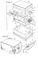
- Figure 1 is a generally perspective exploded view of the nutrient delivery apparatus of the present invention.
- Figure 2 is a perspective view of the apparatus partly broken away to show internal construction and exploded to show the manner of interconnection of the liquid delivery spike.
- Figure 3 is a top-plan view of the device partly broken away to show internal construction.
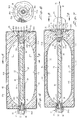
- Figure 4 is a cross-sectional view taken along lines 4-4 of Figure 3.
- Figure 5 is a cross-sectional view taken along lines 5-5 of Figure 4.
- Figure 6 is a fragmentary side-elevational, cross-sectional view of the fill port of the device.
- Figure 7 is a cross-sectional view similar to Figure 4 but illustrating the appearance of the apparatus when filled with fluid.
- Figure 8 is a fragmentary view taken along lines 8-8 of Figure 7.
- Figure 9 is a fragmentary cross-sectional view illustrating one form of the multi-film barrier construction of the device.
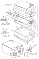
- Figure 10 is a generally perspective exploded view of an alternate form of the apparatus of the invention.
- Figure 10A is a cross-sectional view taken along lines 10A-10A of Figure 10.
- Figure 11 is a cross-sectional view of the check valve assembly of Figure 10.
- Figure 12 is a generally perspective view of the apparatus of Figure 10 partly broken away to show internal construction and exploded to show the manner of interconnection of the delivery spike.
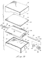
- Figure 13 is a generally perspective exploded view of another embodiment of the nutrient delivery apparatus of the invention.
- Figure 14 is a plan view of the device partly broken away to show internal construction.
- Figure 15 is a cross-sectional view taken along lines 15-15 of Figure 14.
- Figure 16 is a cross-sectional view taken along lines 16-16 of Figure 15.
- Figure 17 is a cross-sectional view taken along lines 17-17 of Figure 15.
- Figure 18 is an enlarged fragmentary view of the outlet portion of the device.
- Figure 19 is an enlarged fragmentary view of the delivery spike of this latest embodiment.
- Figure 20 is a fragmentary cross-sectional view of area 20-20 of Figure 15.
- Figure 21 is an enlarged fragmentary cross-sectional view of the delivery spike mated with the outlet port assembly of the device.
-
- Referring to the drawings and particularly to Figures 1, 2 and 3, the liquid delivery apparatus of the present invention comprises a body made up of cooperating first and
second portions 12a and 12b respectively. As can best be seen by referring to Figure 5, eachbody portion 12a and 12b includes internalwalls defining cavities 14a and 14b respectively with each cavity being circumscribed by anedge numerals - A first
distendable membrane 22 is provided with an edge portion 22a which is disposed in engagement withedge portion 16a of first body portion 12a. A seconddistendable membrane 24 having an edge portion 24a is disposed in engagement withedge portion 16b ofsecond body portion 12b. Each of thedistendable membranes central portion 22b and 24b respectively which spans the cavity of the body portion with which the membrane is associated (Figure 5). - Disposed between
distendable membranes ullage member 26.Support member 26, which can be constructed from any suitable plastic such as polypropylene, polystyrene, polyethylene, or polycarbonate, is provided with a longitudinally extendingfluid passageway 30 which is in communication at one end with afluid inlet port 32 of aninlet port assembly 33 and is in communication at its opposite end with afluid outlet port 34 of anoutlet port assembly 35. Fluidinlet port assembly 33 includes aninlet adapter 36 having aflange portion 36a and aneck portion 36b which is closely received withinapertures 18 provided inbody portions 12a and 12b. Similarly,outlet port 34 includes aflange portion 34a and aneck portion 34b which portion is closely received withinapertures 20 provided inbody portions 12a and 12b. It is to be noted thatbody portions 12a and 12b are also provided with semicircular shaped recessedportions 39 which are adapted to closely receiveflange portion 38a ofoutlet port adapter 38 which in this form of the invention comprises a port of the vent means for permitting the flow of gases between atmosphere and the interior of the liquid delivery apparatus. - Also comprising a part of the liquid delivery apparatus of the form of the invention shown in the drawings is a fluid delivery means which is in communication with the fluid outlet port of the apparatus. In a manner presently to be described, the fluid delivery means functions to deliver fluid to the patient. This fluid delivery means is shown in Figure 2 as comprising a
delivery spike assembly 40, which is adapted to cooperate with the fluidoutlet port assembly 35. - As best seen by referring to Figures 2 and 5,
body portions 12a and 12b are encapsulated by oxygen non-permeable encapsulating barrier means shown here as thin layers ofmaterial body portions 12a and 12b (Figure 9). The character of this sealing material and the manner in which it is applied will be discussed hereinafter. - Receivable within fluid filling
inlet adapter 36 is a check valve assembly comprising a duckbill-type check valve 44 of conventional construction which is held in position withinneck portion 36b by an internally threadedretainer ring 46 which is received overflange portion 36a. A threadedclosure plug 48 is threadably received withinretainer ring 46 in the manner best seen in Figure 4.Duckbill valve 44 includes a yieldably deformable "bill" 44a which functions in the traditional manner illustrated in Figures 6 and 7, permitting fluid to flow inwardly in the direction of the arrows designated by the numerals 50 in Figure 6, but blocking fluid flow in the opposite direction in the manner shown in Figure 7. It is to be understood that various types of check valves of a character well known to those skilled in the art can be used in place of theduckbill valve 44. - Body portions, or
structural support members 12a and 12b can be constructed of any suitable gas permeable, porous material such as Polypropylene (PP), Ultra High Molecular Weight Polyethylene (UHMWPE), High Density Polyethylene (HDPE), Polyvinylidene Fluoride (PVDF), Ethyle-vinyl Acetate (EVA), Styrene Acrylonitrile (SAN), Polytetrafluroethylene (PTFE) and porous cellulose acetate. A suitable source of these materials is Porex Technologies of Fairburn, Georgia. However, practice has shown that any porous plastic material including an open cell, porous sponge material which permits the free passage of gases therethrough is suitable. As described in the following paragraphs, to enable venting of gases from the fluid chamber,membranes - In
practice membranes distendable membranes - The previously mentioned vent means of the invention is adapted to provide for make-up air during liquid delivery so that an even outflow of solution from the apparatus is obtained. To permit the flow of gases between atmosphere and the interior of the apparatus,
flange 38a ofoutlet adapter 38 is provided with circumferentially spacedapertures 38c which permit free flow of air towardfluid chambers 14a and 14b in the manner shown by thearrows 51 in Figure 7. In practice an oxygen impermeablesterile barrier patch 53 is removably affixed to flange 34 so as to coverapertures 38c. - By referring to Figure 8, it can be seen that the encapsulating means, shown here as an outer barrier which surrounds the
body portions 12a and 12b is perforated in the area of theapertures 38c provided in theflange 38. These apertures in the outer barrier permit air from atmosphere to flow into theporous body portions 12a and 12b in the manner shown by the arrows in Figure 7 and designated by the numeral 51. - Turning to Figure 9, the encapsulating means or outer barrier in the embodiment of the invention there shown comprises an
outer paper wrap 42 covering an inner metalized wrap orencapsulation material 41. The outer barrier or encapsulating means can take several forms so long as it produces an oxygen impermeable, anti-microbial leak-free aseptic container. For example, the encapsulation means can comprise a barrier laminate structure which is made up of a plurality of specific high-strength polymer resin layers which effectively prevent formation of pin holes or cracking of oxygen barrier layers during package formation. One type of oxygen impermeable, leak-free container material is disclosed in U.S. Patent No. 4,983,431 issued to Gibbons et al. Disclosures in this patent relating to leak-free packaging are also applicable to the encapsulation means of the aseptic package of the present invention. U.S. Patent No. 3,998,378 issued to Vetten describes methods of fabricating a folding box having a liquid tight cemented bottom and improved stability. Techniques discussed in the Vetten patent can also be used in the construction of the outer barrier or encapsulating means of the present invention. To patents cited in Gibbons, et al. and Vetten are also pertinent to the construction of the encapsulation barrier of the present invention. Other pertinent prior art United States patents include 4,239,150 issued to Schadowski, et al., 4,254,693 issued to Shadowsski, et al., and 4,287, 247 issued to Reil, et al. The teachings of these prior art patents and the patents cited therein are more than adequate to inform those skilled in the art of the various techniques and materials that can be used in fabricating the encapsulating means, including oxygen impermeable aseptic containers, of the invention. - Turning now to Figures 4 and 7, it is to be observed that
outlet port 34 is initially closed by afrangible diaphragm 56 which form an integral part of theoutlet adapter 38. It is also to be noted thatneck 38b ofoutlet adapter 38 is internally threaded withthreads 58 which are adapted to threadably receiveexternal threads 60 provided on thedelivery spike assembly 40.Delivery spike assembly 40 includes an outwardly extending, generally cylindrically shaped portion 40a that terminates in a sharp spike orpoint 40b.point 40b is adapted to piercefrangible membrane 56 when the delivery spike is threadably connected with theoutlet port assembly 34 in the manner illustrated in Figure 7. Anelastomeric O ring 64 is received within agroove 65 provided in cylindrical portion 40a and sealably engages the internal walls ofneck 38b in the manner shown in Figure 7. This prevents leakage of fluid from the pressurized container past the delivery spike and to the outside of the container. - Also forming a part of the delivery spike assembly of this form of the invention is a tubular conduit C that communicate with an external flow rate control means shown here as a
cylindrical housing 65 having contained therewithin a porous mass ofmaterial 67 such as porous TEFLON®, through which the discharging liquid must flow. Flow rate can be precisely controlled by proper selection of the material 67 in a manner well known to those skilled in the art. - In using the apparatus of the present invention, plug 48 is first removed and threadably inserted in its place is a
fill tube 66 having a threaded fitting 68 which is receivable within retaining ring 46 (Figure 6). In the aseptic filling process, the nutrient solution to be delivered to the patient is introduced through thecheck valve 44. The fluid being introduced will impinge uponmembranes support member 26, to a second distended position shown in Figures 6 and 7, wherein the central portions of the membranes are in proximity with the internalwalls defining cavities 14a and 14b. Where permeable elastomeric membranes are used, gas in the solution being introduced into the carton can pass through themembranes porous foam blocks 12a and 12b with subsequent venting at time of use to atmosphere throughorifices 38c. It is to be understood that distention of the membranes from the first to the second position creates internal stresses of predetermined direction and magnitude in the specifically tailored thin films of elastomeric membranes which tend to uniformly return them to their original, non-distended position shown in Figures 4 and 5. - So long as
frangible diaphragm 56 is in tact, the beneficial agent or solution to be delivered to the patient will remain within the device. However, as soon as the diaphragm is ruptured by thedelivery spike 40, the controllably stressedelastomeric membranes delivery passageway 62 of the delivery spike intotube 63 and toward the patient in the direction of thearrow 64 shown in Figure 7. - In certain applications, the retaining
ring 46 andcheck valve assembly 44 can be recessed intobody portions 12a and 12b so that after aseptic filling of the carton is complete, the outer most barrier of the encapsulation means can be folded over the check valve assembly in a manner to effectively seal it relative to atmosphere. - Referring now to Figures 10a, 11 and 12, another form of the liquid delivery apparatus of the present invention is there illustrated. This form of the invention is similar in most respects to the form of the invention described in the preceding paragraphs. Accordingly like numbers have been used to identify like components. The principal differences between this latter embodiment of the invention and the former embodiment resides in the provision of a differently configured
check valve assembly 80 as well as differently configureddistendable membrane assemblies 84. - The check valve assembly of this latter embodiment of the invention comprises an
outer sleeve 86 which is receivable withinfluid inlet 32. Provided proximate the outboard end ofsleeve 86 is aflange 88 which is bondably interconnected withflange 36a of theinlet adapter 36. The check valve member of this alternate form of the invention comprises a generally cylindrically shapedmember 90 having abody portion 92 and a reduceddiameter neck portion 94. Ashoulder 96 is formed at the junction ofneck portion 94 andbody portion 92. Checkvalve member 90 is reciprocally movable withinsleeve 86 from an outward sealing position whereinshoulder 96 sealably engages an internal shoulder provided inmember 88 to a retracted position wherein liquid will be permitted to flow throughinlet port 32 and into pressural communication with thedistendable membrane assemblies 84 of this form of the invention. It should be understood that once the device is pressurized by the filling of the nutritional fluids, thecheck valve member 90 will be urged into a sealing forward position blocking liquid flow outwardly through theinlet port 32. However, during the filling operation, the check valve member is movable rearwardly ofsleeve 86 so as to permit fluid flow through a plurality of circumferentially spacedfluid flow passageways 97 provided in check valve member 90 (Figure 11). - Turning now to Figure 10a, it is to be noted that each of the distendable membranes of this later form of the invention comprises a laminate structure made up of a plurality of layers of
elastomeric material 84a, 84b and 84c. This assemblage functions in much the same way as earlier describeddistendable membranes - The solution contained within the device is delivered to the patient through the
delivery spike assembly 40 in the same manner as was described in the discussion of the previous embodiment. Similarly, make-up air is supplied by the vent means through apertures 38(c) in the manner discussed in the preceding paragraphs. - Referring now to Figures 13, 14, 15 and 16, still another form of the liquid delivery apparatus of the present invention is there illustrated. This latest form of the invention is also similar in many respects to the invention described in the preceding paragraphs. Accordingly, like numbers are used in these figures to identify like components.
- As best seen by referring to Figure 13, the liquid delivery apparatus of this latest form of the invention comprises a
base assembly 100, a carton-like body 102 within which the base assembly is encapsulated and adistendable membrane assembly 104 which overlaysbase assembly 100.Base assembly 100 has a fluid inlet and afluid outlet convex portion 110 which is circumscribed by anedge portion 112.Distendable membrane assembly 104 also includes acentral portion 114 which is circumscribed by upper andlower edge portions distendable membrane assembly 104 can be made up of at least two, but preferably a plurality of thin film distendable membranes 104a, 104b and 104c. For example, layer 104a which is distal to the reservoir comprises a thin film elastomer of a first thickness and a first permeability. On the other hand, layer 104c which is proximal to the reservoir, comprises a thin elastomer film of a second thickness and a second permeability. This film is uniquely selected to be compatible in all respects with the fluid continued within the reservoir. Lay 104b can be of yet another thickness and permeability and, if desired can also have different perm-select characteristics. As previously described, the selective arrangement of the different films, each with its own individual permeability constants in ascending order, will dictate the direction of flow of selected gases and vapors through the stored energy means. - Turning now to Figures 15, 16, and 20, it can be seen that
body assembly 102 includes aninner barrier member 119 havinginternal surfaces 120 which define a cavity orfluid reservoir 122.Barrier member 119 is provided with end flaps (not shown) which can be folded over into the position shown in the drawings after thereservoir 122 is filled in the manner presently to be described.Distendable membrane assembly 104 is distendable from a first position wherein thecentral portion 114 thereof is in close proximity with thecentral portion 110 ofbase assembly 100 to a second distended position whereincentral portion 114 is in close proximity with the upper internal walls 120a of body assembly orcarton 102. The membrane assembly also moves into close proximity with theinternal surfaces 120b ofwalls 120 of the carton (Figure 16) and with the internal surfaces of end walls 120c (Figure 15.) As before, when thedistendable membrane assembly 104 is distended from the first to the second position, internal stresses are developed within the membrane which tend to uniformly return it toward its first position in close proximity with thecentral portion 110 ofbase assembly 100. - Referring to Figures 13, 14, and 16 it can be seen that
base assembly 100 is provided with a longitudinally extendingflow channel 130 which communicates with an internal longitudinally extendingflow passageway 132 that extends between and interconnects togetherinlet 106 andoutlet 108. As best seen in Figure 16,flow passageway 132 is formed internally of a semitubular shaped, longitudinally extendingprotuberance 133 formed integrally withbase assembly 100. - Disposed proximate the inlet portion of
fluid passageway 132 is a check valve assembly generally designated by the numeral 134. Asimilar check valve 136 is disposed proximate the outlet portion offluid passageway 132. Referring to Figure 15, it can be seen thatinlet check valve 134 is receivable within a cylindrically shaped retainingmember 140 which is receivably within an enlarged diameter portion 133a ofprotuberance 133.Member 140 has aninternal shoulder 142 adapted to engage anexternal shoulder 144 formed oncheck valve 134. When thecheck valve 134 is in the closed position shown i Figure 15 whereinshoulder 144 is in engagement withinternal shoulder 142 ofmember 140, the flow of fluid inwardly intofluid passageway 132 is blocked. -
Check valve 136 which is positioned proximate the outlet offluid passageway 132 is held in position within the fluid passageway by aretainer member 146 which is disposed withinpassageway 132 in engagement with an internally threadedoutlet receptacle 147.Outlet receptacle 147 which comprises a part of the vent means of the invention, includes atubular body portion 147a andflange portion 148 having a plurality of circumferentially spaced apertures 150 (Figure 13). As best seen by referring to Figure 15, the reduceddiameter portion 136a ofcheck valve 136 is movably receivable within a bore provided inretainer member 146. With theshoulder 136b of thecheck valve 136 insealable engagement member 146 fluid flow throughpassageway 132 in a direction towardoutlet 108 is effectively blocked. - Also disposed within
fluid passageway 132,intermediate check valves porous filter member 160.Member 160 can be constructed of any inert porous material such as a ceramic or porous plactic, fluid permeable material and can be tailored to provide a precise rate of fluid flow throughpassageway 132 in a manner well known to those skilled in the art. - As best seen in Figure 18, at the outlet portion of the apparatus
tubular body portion 147a ofreceptacle 147 is positioned within anenlarged diameter portion 132a offlow passageway 132 withflange 148 ofmember 147 positioned againstbase assembly 100. A hydrophobic filter vent means for venting air but not moisture is here shown as disk shapedmember 166 which is appropriately bonded to the interior surfaces offlange 148 ofmember 147 in the manner shown in Figure 18. A material such as hydrophobic PTFE, polytetrafluoroethylene incorporating laminated polypropylene or hydrophobic acrylic copolymer supported on nylon nonwoven substrates is suitable for the construction ofmember 166. - With
outlet check valve 136 in a closed position, chamber orreservoir 122 is filled with the selected feeding solution by inserting an appropriate filling conduit into the inlet portion of the device (not shown). The filling conduit is adapted to movecheck valve 134 inwardly permitting the feeding solution to flow intopassageway 132 and then outwardly ofchannel 130 where it impinges onmembrane assembly 104 with sufficient pressure to distend it in to the position shown in Figures 15 and 16. - After
reservoir 122 has been filled, the pressure of the solution within the reservoir will maintain both the inlet andoutlet check valves retainer disk 162 is positioned over the inlet or fillingport 106 and the end flaps ofbarrier member 119 and folded over to holddisk 162 as well asoutlet receptacle 147 in position. This done, an outer barrier layer 167 (Figures 13 and 20) is emplaced over the entire assemblage so as to completely encapsulate it within a sealed oxygen impermeable, antimicrobial, leak-free aseptic container of the character previously described herein. Finally a disk shapedmetalized seal 168 is positioned over the outer barrier in the proximity of the vent means orflange 148 ofoutlet receptacle 147. The apparatus of the invention is now ready for shipment storage and subsequent use in the field. - The feeding solution contained within
reservoir 122 is accessed by adelivery spike 170 of a construction similar todelivery spike 140 of the earlier described embodiments. As shown in Figure 19,delivery spike 170 comprises afinger grip portion 172, aflange portion 174 and an externally threadedneck portion 176. For a purpose presently to be described, a plurality of circumferentially spaced, outwardly extending pointedprotuberances 177 are provided onflange portion 174. - Turning now to Figure 21, upon piercing the
metalized seal 168 and the barrier layers 119 and 167, threads provided onneck portion 176 of the delivery spike can be moved into threadable engagement with theinternal threads 181 provided onoutlet receptacle 147 in the manner shown in Figure 21. As the neck portion of the delivery spike advances intoreceptacle 147, the end of the neck portion will engageoutlet check valve 136 moving it into an open position which will permit liquid withinreservoir 122 to flow throughchannel 130, intopassageway 132 and then intocentral passageway 180 provided in the delivery spike. Aselastomeric O ring 182 is carried byneck portion 176 for engagement with the internal wall of the outlet receptacle to prevent leakage of the feeding solution past the delivery spike. - As illustrated in Figure 21, as the
check valve 136 is moved into the open position,protuberances 177 will pierce metalizedseal 168 and will extend intovent apertures 150 thereby creating openings which permit make-up air to flow into the device as the feeding solution is introduced into the patient. - Having now described the invention in detail in accordance with the requirements of the patent statutes, those skilled in this art will have no difficulty in making changes and modifications in the individual parts or their relative assembly in order to meet specific requirements or conditions. Such changes and modifications may be made without departing from the scope of the invention, as set forth in the following claims.
Claims (19)
- A liquid delivery apparatus comprising:(a) a housing (12a, 12b; 12a, 12b; 102) having internal walls (120) defining a cavity (14a, 14b; 14a, 14b; 122);(b) a support (26; 26; 100) disposed within said housing having a central portion (110), an edge portion (112) circumscribing said central portion and including a liquid passageway (30; 30; 130; 132) in communication with said cavity of said housing, said liquid passageway having an inlet (32; 32; 106) and an outlet (34; 34; 108);(c) a distendable membrane (22; 84) or a distendable membrane assembly (104) having a central portion (22b; 114) circumscribed by an edge (22a; 116, 118), said central portion spanning said central portion of said support with said edge being disposed in engagement with said edge portion of said support, said distendable membrane or membrane assembly being distendable from a first position wherein said central portion is in close proximity with said support to a second position wherein said central portion is in close proximity of said internal walls defining said cavity, said distendable membrane or membrane assembly in said second position having internal stresses tending to return it to said first position, characterised by(d) means for sealably encapsulating said housing (12a, 12b; 12a, 12b; 102), said distendable membrane (22; 84) or membrane assembly (104) and said support (26; 26; 100), said means comprising an oxygen impermeable barrier (41, 42; 41, 42; 119, 167) surrounding said housing; and(e) means (38; 38; 147) for permitting the flow of gases between atmosphere and said cavity (14a, 14b; 14a, 14b; 122) of said housing as said distendable membrane or membrane assembly moves from said second position to said first position.
- A liquid delivery apparatus as defined in claim 1, wherein said cavity (14a, 14b; 14a, 14b; 122) being circumscribed by an edge (16a, 16b; 16a, 16b).
- A liquid delivery apparatus as defined in claim 1 or 2, further including a pair of porous bodies (12a, 12b; 12a, 12b) disposed interiorly of said cavity, each said body having internal walls defining a cavity (14a, 14b; 14a, 14b), said support (26; 26) being disposed between said porous bodies.
- A liquid delivery apparatus as defined in claim 3 further including a second distendable membrane (24; 84) having a central portion (24b) distendable from a first position in proximity with said support (26; 26) to a second position in proximity with said internal walls of one of said porous bodies (12b; 12b).
- An apparatus as defined in claim 4 in which distension of said second membrane (24; 84) from said first to said second position creates internal stresses tending to return said membrane to said first position.
- An apparatus as defined in claim 5 in which said distendable membranes (24; 84) comprise multi-layers (84a, 84b, 84c) of elastic material.
- An apparatus as defined in claim 1 or 2, wherein the distendable membrane assembly (104) comprises a plurality of thin films (104a, 104b, 104c).
- An apparatus as defined in claim 7 in which said distendable membrane assembly (104) comprises a first interior layer (104c) constructed of a material fully compatible with the liquid to be delivered.
- An apparatus as defined in claim 7 or 8, further including a second distendable membrane assembly comprising a plurality of thin films, said assembly having a central portion spanning the cavity (122) in said second body portion (102) with said edge being disposed in engagement with said edge of said second body portion.
- An apparatus as defined in claim 9, wherein the support (100) is disposed intermediate the first and second distendable membrane assemblies (104).
- An apparatus as defined in claims 5, 6 or 10, further including liquid delivery means (38, 40; 38, 40; 147, 170) in communication with said outlet (34; 34; 108) for delivering liquid from said apparatus.
- An apparatus as defined in claim 11, wherein said liquid delivery means (38, 40; 38, 40; 147, 170) in communication with said outlet (34; 34; 108) for delivering liquid to a patient.
- An apparatus as defined in claim 11 or 12, further including a frangible diaphragm (56; 168) for closing said outlet (34; 34; 108) of said support (26; 26; 100).
- An apparatus as defined in claim 13 further including said liquid delivery means having coupling means (58, 60; 181, 179) for interconnection with said outlet (34; 34; 108) of said support (26; 26; 100) and spike means (40; 40; 170) for rupturing said frangible diaphragm (56; 168) upon interconnection of said coupling means with said outlet.
- An apparatus as defined in claims 6, 9, 10, 11, 12, 13 or 14 further including check valve means (44; 80; 134) disposed within said inlet (32; 32; 106) of said support (26; 26; 100) for permitting fluid flow in a first direction and for blocking fluid flow in a second direction.
- An apparatus as defined in claims 6, 9, 10, 11, 12, 13, 14 or 15 in which said outlet (34; 34; 108) includes vent means (38c; 38c; 150) for venting gases from said cavities (14a, 14b; 14a, 14b; 122) to atmosphere.
- An apparatus as defined in claim 16, further including closure means (53; 53; 168) for closing said vent means (38c; 38c, 150).
- An apparatus as defined in claims 6, 11, 12, 13, 14, 15, 16 or 17 in which said liquid delivery means (38, 40; 38, 40) includes flow control means (65, 67) disposed externally of said encapsulating means (41, 42; 41, 42) for controlling the rate of liquid flow to the patient.
- A liquid delivery apparatus as defined in claim 9, 10, 11, 12, 13, 14, 15, 16 or 17 further including flow rate control means (160) disposed interiorly of said liquid passageway (132) of said support (100) for controlling the rate of low of fluid through said passageway.
Applications Claiming Priority (3)
| Application Number | Priority Date | Filing Date | Title |
|---|---|---|---|
| US07/870,403 US5314405A (en) | 1992-04-17 | 1992-04-17 | Liquid delivery apparatus |
| US870403 | 1992-04-17 | ||
| PCT/US1993/003366 WO1993020862A1 (en) | 1992-04-17 | 1993-04-08 | Liquid delivery apparatus |
Publications (3)
| Publication Number | Publication Date |
|---|---|
| EP0636034A1 EP0636034A1 (en) | 1995-02-01 |
| EP0636034A4 EP0636034A4 (en) | 1996-04-17 |
| EP0636034B1 true EP0636034B1 (en) | 1999-08-11 |
Family
ID=25355306
Family Applications (1)
| Application Number | Title | Priority Date | Filing Date |
|---|---|---|---|
| EP93912173A Expired - Lifetime EP0636034B1 (en) | 1992-04-17 | 1993-04-08 | Liquid delivery apparatus |
Country Status (10)
| Country | Link |
|---|---|
| US (1) | US5314405A (en) |
| EP (1) | EP0636034B1 (en) |
| JP (1) | JPH07507939A (en) |
| AU (1) | AU667377B2 (en) |
| BR (1) | BR9306256A (en) |
| CA (1) | CA2118040A1 (en) |
| DE (1) | DE69325997T2 (en) |
| ES (1) | ES2141156T3 (en) |
| RU (1) | RU94045990A (en) |
| WO (1) | WO1993020862A1 (en) |
Cited By (1)
| Publication number | Priority date | Publication date | Assignee | Title |
|---|---|---|---|---|
| DE102010026848A1 (en) * | 2010-07-12 | 2012-01-12 | Human Nutrition Gmbh | System for direct application of e.g. food from cardboard package to patient in clinic, has long spike attached at end of transfer system, where length of long spike corresponds to height of cardboard package |
Families Citing this family (35)
| Publication number | Priority date | Publication date | Assignee | Title |
|---|---|---|---|---|
| US7169128B2 (en) | 2003-08-04 | 2007-01-30 | Bioquiddity, Inc. | Multichannel fluid delivery device |
| US7220244B2 (en) * | 2003-08-04 | 2007-05-22 | Bioquiddity, Inc. | Infusion apparatus with constant force spring energy source |
| US20050033232A1 (en) * | 2003-08-05 | 2005-02-10 | Kriesel Marshall S. | Infusion apparatus with modulated flow control |
| US7470253B2 (en) * | 2004-05-26 | 2008-12-30 | Bioquiddity, Inc. | Fluid delivery apparatus with adjustable flow rate control |
| US20050277884A1 (en) * | 2004-05-26 | 2005-12-15 | Kriesel Marshall S | Fluid delivery apparatus with bellows reservoir |
| US20070156090A1 (en) * | 2004-05-26 | 2007-07-05 | Kriesel Marshall S | Fluid delivery apparatus |
| US7220245B2 (en) * | 2004-05-26 | 2007-05-22 | Kriesel Marshall S | Infusion apparatus |
| US20050277883A1 (en) * | 2004-05-26 | 2005-12-15 | Kriesel Marshall S | Fluid delivery device |
| US8029468B2 (en) * | 2005-02-15 | 2011-10-04 | Bioquiddity, Inc. | Fluid delivery and mixing apparatus with flow rate control |
| US20080009835A1 (en) * | 2005-02-17 | 2008-01-10 | Kriesel Marshall S | Fluid dispensing apparatus with flow rate control |
| US7694938B2 (en) * | 2005-02-17 | 2010-04-13 | Bioquiddity, Inc. | Distal rate control device |
| US7837653B2 (en) * | 2005-02-18 | 2010-11-23 | Bioquiddity, Inc. | Fluid delivery apparatus with vial fill |
| JP2007055059A (en) * | 2005-08-24 | 2007-03-08 | Seiko Epson Corp | Capturing member and ink-jet printer |
| US7896859B2 (en) * | 2005-10-20 | 2011-03-01 | Tyco Healthcare Group Lp | Enteral feeding set |
| US7611502B2 (en) * | 2005-10-20 | 2009-11-03 | Covidien Ag | Connector for enteral fluid delivery set |
| US20070118078A1 (en) * | 2005-11-18 | 2007-05-24 | Mcnally David J | Method and apparatus for controlled feeding of an infant |
| US7993304B2 (en) * | 2006-03-15 | 2011-08-09 | Bioquiddity, Inc. | Fluid dispensing apparatus |
| US7828772B2 (en) * | 2006-03-15 | 2010-11-09 | Bioquiddity, Inc. | Fluid dispensing device |
| US8292848B2 (en) | 2006-07-31 | 2012-10-23 | Bio Quiddity, Inc. | Fluid dispensing device with additive |
| US8057435B2 (en) | 2006-07-31 | 2011-11-15 | Kriesel Joshua W | Fluid dispenser |
| US7703848B1 (en) * | 2006-10-16 | 2010-04-27 | Cochran David B | Vehicle sound and vibration simulator for use with an infant vehicle seat |
| US20080243077A1 (en) * | 2007-04-02 | 2008-10-02 | Bivin Donald B | Fluid dispenser with uniformly collapsible reservoir |
| US20080319385A1 (en) * | 2007-06-25 | 2008-12-25 | Kriesel Marshall S | Fluid dispenser with additive sub-system |
| US8211059B2 (en) * | 2007-06-25 | 2012-07-03 | Kriesel Marshall S | Fluid dispenser with additive sub-system |
| JP5071948B2 (en) * | 2007-10-11 | 2012-11-14 | アー サン パン, | Equipment for tube feeding |
| US8231597B2 (en) * | 2008-02-08 | 2012-07-31 | Codan Us Corporation | Enteral feeding safety reservoir and system |
| US8539672B2 (en) | 2010-10-01 | 2013-09-24 | Zevex, Inc. | Method for improving accuracy in a peristaltic pump system based on tubing material properties |
| JP2013165757A (en) * | 2012-02-14 | 2013-08-29 | Icomes Labo:Kk | Transfusion device |
| US8985202B2 (en) * | 2012-05-29 | 2015-03-24 | P.V. Flood Control Corp. | System for containment, measurement, and reuse of fluids in hydraulic fracturing |
| CN103331187B (en) * | 2013-06-25 | 2015-07-15 | 益善生物技术股份有限公司 | Liquid transfer linking device |
| AU2017215419B2 (en) * | 2016-02-05 | 2019-11-21 | Innopharma, Inc. | Process of manufacturing a stable, ready to use infusion bag for an oxidation sensitive formulation |
| PL3290063T3 (en) * | 2016-09-06 | 2019-04-30 | FRITZ RUCK Ophthalmologische Systeme GmbH | Pressure regulation system |
| WO2018111607A1 (en) | 2016-12-16 | 2018-06-21 | Kimberly-Clark Worldwide, Inc. | Fluid delivery apparatus having a gas extraction device and method of use |
| CN110882439A (en) * | 2018-09-07 | 2020-03-17 | 朱永坚 | Energy-storage type infusion device |
| WO2023147491A2 (en) * | 2022-01-28 | 2023-08-03 | Aktivax, Inc. | Packaging system for storage of a perishable product |
Family Cites Families (22)
| Publication number | Priority date | Publication date | Assignee | Title |
|---|---|---|---|---|
| US3111125A (en) * | 1961-11-06 | 1963-11-19 | Rudolf R Schulte | Drainage device |
| US3468308A (en) * | 1966-01-17 | 1969-09-23 | Howard R Bierman | Pressure infusion device for ambulatory patients with pressure control means |
| US3595240A (en) * | 1968-08-07 | 1971-07-27 | Alan J Mishler | Hydrocephalus shunt with two-way flushing means |
| US3769982A (en) * | 1971-09-24 | 1973-11-06 | R Schulte | Physiological drainage system with closure means responsive to downstream suction |
| SE419326B (en) * | 1975-05-07 | 1981-07-27 | Jagenberg Werke Ag | WASHED PACKAGING WITH THE BOTTOM BOTTOM |
| DE2750835C3 (en) * | 1977-11-14 | 1980-06-19 | Jagenberg-Werke Ag, 4000 Duesseldorf | Device for the continuous peeling off of longitudinal strips from a packaging web |
| DE2750901A1 (en) * | 1977-11-14 | 1979-05-17 | Linnich Papier & Kunststoff | FOLDING BOXES FOR LIQUIDS |
| SE424177B (en) * | 1978-09-04 | 1982-07-05 | Tetra Pak Int | BIG LINE PACKAGED LAMINATE |
| US4681560A (en) * | 1984-03-16 | 1987-07-21 | Pudenz-Schulte Medical Research Corp. | Subcutaneous infusion reservoir and pump system |
| US4761158A (en) * | 1984-03-16 | 1988-08-02 | Pudenz-Schulte Medical Research Corp. | Subcutaneous infusion reservoir and pump system |
| US4816016A (en) * | 1984-03-16 | 1989-03-28 | Pudenz-Schulte Medical Research Corp. | Subcutaneous infusion reservoir and pump system |
| US4688595A (en) * | 1986-02-20 | 1987-08-25 | Sherwood Medical Company | Enteral nutrition delivery system |
| US4722732A (en) * | 1986-10-20 | 1988-02-02 | James Martin | Intravenous fluid supply system |
| US4781672A (en) * | 1986-10-21 | 1988-11-01 | Cordis Corporation | Three stage implantable flow control valve with improved valve closure member |
| US4826500A (en) * | 1987-10-16 | 1989-05-02 | Rautsola Riku H | Enteral nutrient delivery system |
| US4979937A (en) * | 1987-12-22 | 1990-12-25 | Khorasani Ahmad R | Method and apparatus involving intercostal and lumbar perfusion |
| WO1989011309A1 (en) * | 1988-05-16 | 1989-11-30 | Terumo Kabushiki Kaisha | Subcutaneously implanted catheter assembly |
| US4983431A (en) * | 1989-05-22 | 1991-01-08 | International Paper Company | Oxygen impermeable leak free container |
| US4953753A (en) * | 1988-06-10 | 1990-09-04 | The Norman Company | Fluid dispensing apparatus with prestressed bladder |
| US4995856A (en) * | 1989-06-14 | 1991-02-26 | Pudenz-Schulte Medical Research Corporation | Ventriculostomy reservoir |
| US4995864A (en) * | 1989-08-15 | 1991-02-26 | Imed Corporation | Dual chamber pumping apparatus |
| US5080652A (en) * | 1989-10-31 | 1992-01-14 | Block Medical, Inc. | Infusion apparatus |
-
1992
- 1992-04-17 US US07/870,403 patent/US5314405A/en not_active Expired - Fee Related
-
1993
- 1993-04-08 JP JP5518506A patent/JPH07507939A/en active Pending
- 1993-04-08 AU AU42822/93A patent/AU667377B2/en not_active Ceased
- 1993-04-08 EP EP93912173A patent/EP0636034B1/en not_active Expired - Lifetime
- 1993-04-08 DE DE69325997T patent/DE69325997T2/en not_active Expired - Fee Related
- 1993-04-08 BR BR9306256-7A patent/BR9306256A/en not_active Application Discontinuation
- 1993-04-08 ES ES93912173T patent/ES2141156T3/en not_active Expired - Lifetime
- 1993-04-08 WO PCT/US1993/003366 patent/WO1993020862A1/en active IP Right Grant
- 1993-04-08 CA CA002118040A patent/CA2118040A1/en not_active Abandoned
- 1993-04-08 RU RU94045990/14A patent/RU94045990A/en unknown
Cited By (2)
| Publication number | Priority date | Publication date | Assignee | Title |
|---|---|---|---|---|
| DE102010026848A1 (en) * | 2010-07-12 | 2012-01-12 | Human Nutrition Gmbh | System for direct application of e.g. food from cardboard package to patient in clinic, has long spike attached at end of transfer system, where length of long spike corresponds to height of cardboard package |
| DE102010026848B4 (en) * | 2010-07-12 | 2015-09-10 | Human Nutrition Gmbh | System for the direct application of enteral nutrition from a cardboard packaging |
Also Published As
| Publication number | Publication date |
|---|---|
| ES2141156T3 (en) | 2000-03-16 |
| AU667377B2 (en) | 1996-03-21 |
| WO1993020862A1 (en) | 1993-10-28 |
| BR9306256A (en) | 1999-09-28 |
| US5314405A (en) | 1994-05-24 |
| JPH07507939A (en) | 1995-09-07 |
| CA2118040A1 (en) | 1993-10-28 |
| AU4282293A (en) | 1993-11-18 |
| RU94045990A (en) | 1996-08-27 |
| EP0636034A4 (en) | 1996-04-17 |
| EP0636034A1 (en) | 1995-02-01 |
| DE69325997D1 (en) | 1999-09-16 |
| DE69325997T2 (en) | 2000-04-27 |
Similar Documents
| Publication | Publication Date | Title |
|---|---|---|
| EP0636034B1 (en) | Liquid delivery apparatus | |
| US5372578A (en) | Liquid delivery apparatus | |
| CA2081116C (en) | Closed drug delivery system | |
| US5514090A (en) | Closed drug delivery system | |
| EP0278015B1 (en) | Variable-volume vented container | |
| CN104334213B (en) | Multiple dose vials and method | |
| EP0378141B1 (en) | Medical piercing cannula with drip chamber | |
| US4335770A (en) | Enteral feeding container | |
| KR102506175B1 (en) | Pooling device for single or multiple containers | |
| US6245041B1 (en) | Fluid dispenser with fill adapter | |
| DK170246B1 (en) | Parenteral fluid administration equipment | |
| US5267957A (en) | Closed drug delivery system | |
| US5941866A (en) | Means to maintain configuration of flexible medical container | |
| US5257986A (en) | Container for the separate sterile storage of at least two substances and for mixing said substances | |
| US5352201A (en) | Compact uniform pressure infusion apparatus | |
| US5738671A (en) | Flexible plastic container for the containment and delivery of diagnostic contrast media and parenteral drug formulations | |
| EP0113597A2 (en) | Container | |
| EP1031341B1 (en) | Collapsible medical bag for the containment and delivery of diagnostic contrast media and parenteral drug formulations | |
| US6086560A (en) | Fluid dispenser with fill adapter | |
| AU700421B2 (en) | Fluid delivery apparatus |
Legal Events
| Date | Code | Title | Description |
|---|---|---|---|
| PUAI | Public reference made under article 153(3) epc to a published international application that has entered the european phase |
Free format text: ORIGINAL CODE: 0009012 |
|
| 17P | Request for examination filed |
Effective date: 19941017 |
|
| AK | Designated contracting states |
Kind code of ref document: A1 Designated state(s): CH DE ES FR GB IT LI NL SE |
|
| A4 | Supplementary search report drawn up and despatched |
Effective date: 19960227 |
|
| AK | Designated contracting states |
Kind code of ref document: A4 Designated state(s): CH DE ES FR GB IT LI NL SE |
|
| 17Q | First examination report despatched |
Effective date: 19971114 |
|
| GRAG | Despatch of communication of intention to grant |
Free format text: ORIGINAL CODE: EPIDOS AGRA |
|
| GRAG | Despatch of communication of intention to grant |
Free format text: ORIGINAL CODE: EPIDOS AGRA |
|
| GRAH | Despatch of communication of intention to grant a patent |
Free format text: ORIGINAL CODE: EPIDOS IGRA |
|
| GRAH | Despatch of communication of intention to grant a patent |
Free format text: ORIGINAL CODE: EPIDOS IGRA |
|
| GRAA | (expected) grant |
Free format text: ORIGINAL CODE: 0009210 |
|
| RAP1 | Party data changed (applicant data changed or rights of an application transferred) |
Owner name: SCIENCE INCORPORATED |
|
| AK | Designated contracting states |
Kind code of ref document: B1 Designated state(s): CH DE ES FR GB IT LI NL SE |
|
| PG25 | Lapsed in a contracting state [announced via postgrant information from national office to epo] |
Ref country code: NL Free format text: LAPSE BECAUSE OF FAILURE TO SUBMIT A TRANSLATION OF THE DESCRIPTION OR TO PAY THE FEE WITHIN THE PRESCRIBED TIME-LIMIT Effective date: 19990811 Ref country code: LI Free format text: LAPSE BECAUSE OF FAILURE TO SUBMIT A TRANSLATION OF THE DESCRIPTION OR TO PAY THE FEE WITHIN THE PRESCRIBED TIME-LIMIT Effective date: 19990811 Ref country code: CH Free format text: LAPSE BECAUSE OF FAILURE TO SUBMIT A TRANSLATION OF THE DESCRIPTION OR TO PAY THE FEE WITHIN THE PRESCRIBED TIME-LIMIT Effective date: 19990811 |
|
| REG | Reference to a national code |
Ref country code: CH Ref legal event code: EP |
|
| REF | Corresponds to: |
Ref document number: 69325997 Country of ref document: DE Date of ref document: 19990916 |
|
| ITF | It: translation for a ep patent filed |
Owner name: BREMA S.R.L. |
|
| ET | Fr: translation filed | ||
| NLV1 | Nl: lapsed or annulled due to failure to fulfill the requirements of art. 29p and 29m of the patents act | ||
| REG | Reference to a national code |
Ref country code: CH Ref legal event code: PL |
|
| REG | Reference to a national code |
Ref country code: ES Ref legal event code: FG2A Ref document number: 2141156 Country of ref document: ES Kind code of ref document: T3 |
|
| PGFP | Annual fee paid to national office [announced via postgrant information from national office to epo] |
Ref country code: GB Payment date: 20000405 Year of fee payment: 8 |
|
| PGFP | Annual fee paid to national office [announced via postgrant information from national office to epo] |
Ref country code: DE Payment date: 20000407 Year of fee payment: 8 |
|
| PGFP | Annual fee paid to national office [announced via postgrant information from national office to epo] |
Ref country code: SE Payment date: 20000417 Year of fee payment: 8 |
|
| PGFP | Annual fee paid to national office [announced via postgrant information from national office to epo] |
Ref country code: FR Payment date: 20000419 Year of fee payment: 8 |
|
| PLBE | No opposition filed within time limit |
Free format text: ORIGINAL CODE: 0009261 |
|
| STAA | Information on the status of an ep patent application or granted ep patent |
Free format text: STATUS: NO OPPOSITION FILED WITHIN TIME LIMIT |
|
| 26N | No opposition filed | ||
| PG25 | Lapsed in a contracting state [announced via postgrant information from national office to epo] |
Ref country code: GB Free format text: LAPSE BECAUSE OF NON-PAYMENT OF DUE FEES Effective date: 20010408 |
|
| PG25 | Lapsed in a contracting state [announced via postgrant information from national office to epo] |
Ref country code: SE Free format text: LAPSE BECAUSE OF NON-PAYMENT OF DUE FEES Effective date: 20010409 |
|
| PG25 | Lapsed in a contracting state [announced via postgrant information from national office to epo] |
Ref country code: FR Free format text: THE PATENT HAS BEEN ANNULLED BY A DECISION OF A NATIONAL AUTHORITY Effective date: 20010430 |
|
| PGFP | Annual fee paid to national office [announced via postgrant information from national office to epo] |
Ref country code: ES Payment date: 20010531 Year of fee payment: 9 |
|
| GBPC | Gb: european patent ceased through non-payment of renewal fee |
Effective date: 20010408 |
|
| EUG | Se: european patent has lapsed |
Ref document number: 93912173.7 |
|
| PG25 | Lapsed in a contracting state [announced via postgrant information from national office to epo] |
Ref country code: DE Free format text: LAPSE BECAUSE OF NON-PAYMENT OF DUE FEES Effective date: 20020201 |
|
| REG | Reference to a national code |
Ref country code: FR Ref legal event code: ST |
|
| PG25 | Lapsed in a contracting state [announced via postgrant information from national office to epo] |
Ref country code: ES Free format text: LAPSE BECAUSE OF NON-PAYMENT OF DUE FEES Effective date: 20020409 |
|
| REG | Reference to a national code |
Ref country code: ES Ref legal event code: FD2A Effective date: 20030514 |
|
| PG25 | Lapsed in a contracting state [announced via postgrant information from national office to epo] |
Ref country code: IT Free format text: LAPSE BECAUSE OF NON-PAYMENT OF DUE FEES;WARNING: LAPSES OF ITALIAN PATENTS WITH EFFECTIVE DATE BEFORE 2007 MAY HAVE OCCURRED AT ANY TIME BEFORE 2007. THE CORRECT EFFECTIVE DATE MAY BE DIFFERENT FROM THE ONE RECORDED. Effective date: 20050408 |