EP0635974B1 - Built in television for kitchen furniture, comprising an electronic cookery book - Google Patents
Built in television for kitchen furniture, comprising an electronic cookery book Download PDFInfo
- Publication number
- EP0635974B1 EP0635974B1 EP94111612A EP94111612A EP0635974B1 EP 0635974 B1 EP0635974 B1 EP 0635974B1 EP 94111612 A EP94111612 A EP 94111612A EP 94111612 A EP94111612 A EP 94111612A EP 0635974 B1 EP0635974 B1 EP 0635974B1
- Authority
- EP
- European Patent Office
- Prior art keywords
- control unit
- remote control
- television
- television system
- recipes
- Prior art date
- Legal status (The legal status is an assumption and is not a legal conclusion. Google has not performed a legal analysis and makes no representation as to the accuracy of the status listed.)
- Expired - Lifetime
Links
Images


Classifications
-
- H—ELECTRICITY
- H04—ELECTRIC COMMUNICATION TECHNIQUE
- H04N—PICTORIAL COMMUNICATION, e.g. TELEVISION
- H04N5/00—Details of television systems
- H04N5/44—Receiver circuitry for the reception of television signals according to analogue transmission standards
Definitions
- the present invention refers to a television.
- kitchens are, more recently, almost always furnished with so-called fitted kitchens, made up of shelving units and floor based cabinets; said furnishings also provide for building in, or built in, electric appliances, usually found in the kitchen, such as the refrigerator and the dishwasher; such built in arrangements provide for the colours and materials of the electrical appliances to be in complete harmony with those of the actual furnishings.
- a kitchen apparatus with electronic controlling device.
- Such apparatus shows a holding frame with various supporting elements, power supplying elements and control elements.
- a number of kitchen modules can be attached to the holding frame. Attaching the modules to the holding frame they are connected to power supplying devices and to electronic control devices.
- the aim of the present invention is that of indicating how it is possible to realise a television particularly apt for being utilised in a kitchen and which shows for the user advantages over the known apparatuses.
- the subject of the present invention is a television system having the characteristics listed in the attached main claim.
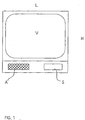
- Figure 1 represents a frontal view of a television according to the invention
- the reference symbol V indicates the television screen
- the reference symbol A a frontal speaker is indicated
- the reference symbol S an access flap to the commands of the apparatus is indicated
- reference symbol L indicates the width of the television's cabinet
- reference symbol H the height of the television's cabinet is indicated.
- the width L of the television has been chosen in the present example as 45cm; as a result the screen S results in being 20'' (diagonal), which is a suitable dimension for a kitchen; naturally it is also possible to utilise a different screen, for example 26'' (with a dimension L of 60cm).
- the dimension H in the given figure, is 40cm.
- FIG 2 two possible arrangements of the television according to the invention are represented in a kitchen; in part a) of figure 2 a corner of a kitchen is schematically represented; a television is seen towards the top, indicated with the symbol TV, against a wall (and naturally arranged above a base cabinet, or incorporated in a column, as is usual for example with ovens); on the other wall, to the right, a cooking hob is seen, indicated with symbol P.
- the television's remote control unit TC is indicated, that shall be described in detail in the following.
- part b) of figure 2 another possible arrangement is schematically represented: to the top, against a wall, incorporated in a series of fitted cabinets, the television can be seen, indicated with the symbol TV; below a dependent cabinet is visible to which a cooking hob is incorporated, indicated with the symbol P. Also here, to the right of the hob, the remote control of the television is visible, indicated with the symbol TC.
- Such remote control unit that functions according to the principle of infrared rays, must be directed towards the television for its correct functioning.
- a housing for the remote control unit, to the side of the cooking hob, is provided, so as that the user, that is cooking, or is about to cook, has it easily at hand without having to search for it, as is usually the case; with the aims of ease of use it is provided that upon pressing the remote control, it is spring released from its housing, remaining however anchored to its support; said support can be revolved so as to allow it to be pointed in the direction of the television. After use the remote control is made to enter once more in its housing by pressing an appropriate button situated on the edge of the hob.
- the remote control be waterproof and dust proof, according to known techniques already used for electrical appliances.
- the cabinet that has to house the television in the case that it is not simply free standing on a shelf, has to provide for, in its lower section, a so called chimney such as those used, for example, with built in refrigerators.
- This detail has the aim of permitting a suitable air flow for the television that could otherwise suffer from breakdowns caused by overheating of the television itself.
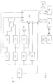
- Figure 3 schematically represents the block diagram of the electrical circuit of the television according to the invention; in figure 3; reference number 10 indicates the block of the tuning and amplification circuits of the television signals received by the antenna 9; with reference number 11 the block of the decoding and matrixing circuits of the luminance and chrominace video signals is indicated; reference number 12 indicates the block of the extraction circuits of the synchronism video signals; reference number 13 indicates the block of the amplification and decoding circuits of the audio signal; reference number 14 indicates the block of the amplification circuits of the colour signals R,G,B; reference number 15 indicates the block of the deflexion signals generation circuits for the image display device; reference number 16 indicatesthe block of the amplification circuits of the audio signal; reference number 17 indicates the image display device, for example a coloured picture tube; reference number 18 indicates the sonorous reproduction device, for example a loud speaker; reference number 19 indicates the block of the circuits for the extraction and decoding of the teletext signal.
- reference number 10 indicates the block of the tuning and amplification
- reference number 20 indicates the block of the control circuits, being specific to the television according to the invention; block 20 may for example be realised utilising a microprocessor, joined to a read and write memory (RAM, indicated with reference number 47), preferably of the non-volatile type, and to a read only permanent memory (ROM, indicated with reference number 48).
- RAM read and write memory
- ROM read only permanent memory
- teletext pages can be stored for example containing cookery recipes (Televideo by RAI transmits for instance at least one recipe daily on page 627); with this in mind the remote control unit TC can be provided with an appropriate memory key that, upon being pressed by the user, provides for storing in the RAM memory the displayed teletext page.
- cookery recipes Televideo by RAI transmits for instance at least one recipe daily on page 627
- the remote control unit TC can be provided with an appropriate memory key that, upon being pressed by the user, provides for storing in the RAM memory the displayed teletext page.
- ROM memory Stored in the ROM memory on the other hand, according to the invention, are not only the operative instructions for the microprocessor, but also a series of arranged recipes, making up a cookery book, to which the user may have access, guided by an appropriate operative menu, for consultation.
- the two memories are connected to the control unit 20 by way of a bus, as is normal.
- the control unit 20 is also connected to a circuit, indicated with reference number 49, that has the function of a receiver of signals of infrared rays, coming from the remote control unit TC, that comprises a transmitter, indicated with the reference number 51, and a command key board, indicated with reference number 50, to which the transmitter 51 is in turn connected.
- a circuit indicated with reference number 49, that has the function of a receiver of signals of infrared rays, coming from the remote control unit TC, that comprises a transmitter, indicated with the reference number 51, and a command key board, indicated with reference number 50, to which the transmitter 51 is in turn connected.
- FIG 4 an example of a screen display is represented showing a cookery recipe.
- the presentation of a screen display is provided in the form of a menu for guiding the user in the choice of the recipes stored in the ROM 48; in a preferred embodiment of the invention such menu allows for various possibilities of access, managed by the control circuit 20.
- control unit 20 can be connected, by way of a bus, to an available external plug-socket, to which it is possible to connect other computerised electrical appliances so as to obtain a display of command data and control signals coming from the same.
- the television according to the invention results in being extremely practical for the user that in the kitchen can, so to say, combine the useful with amusement, being able to follow favourite television programs and always having the availability of a handy cookery book that will never be lost.
- the appropriate positioning of the television in the kitchen, and the specific positioning of the remote control unit eases the consultation of the cookery book, without the user having to leave the vicinity of the cooker, that, as is known, requires constant surveillance.
- a possible variant could be that of providing the use of a part of the RAM 47 as a memorandum of notes of things to buy; in such a case the key board of the remote control will be able to generate alphanumeric signals; in particular, the ROM 48 could have a dictionary of the things that usually are needed in a kitchen and the remote control unit could provide the possibility of scrolling the items stored and, when those that are needed have been found, place them in the display of the memorandum.
Description
- The present invention refers to a television.
- It is known that nowadays every family generally owns more than one television, and that, usually, one of them is situated in the kitchen, being that this is the room of the house that is most frequently used.
- It is also known that kitchens are, more recently, almost always furnished with so-called fitted kitchens, made up of shelving units and floor based cabinets; said furnishings also provide for building in, or built in, electric appliances, usually found in the kitchen, such as the refrigerator and the dishwasher; such built in arrangements provide for the colours and materials of the electrical appliances to be in complete harmony with those of the actual furnishings.
- It is known from DE-A-31 20 723 a kitchen apparatus with electronic controlling device. Such apparatus shows a holding frame with various supporting elements, power supplying elements and control elements. A number of kitchen modules can be attached to the holding frame. Attaching the modules to the holding frame they are connected to power supplying devices and to electronic control devices.
- It is also known from US-A-4,628,351 a cooking apparatus with a video display, which includes a video signal processing unit and is able to process TV programs, video signals from video cameras from any desired location (such as an outside entrance or infant's room) and cooking information stored in a microprocessor.
- The aim of the present invention is that of indicating how it is possible to realise a television particularly apt for being utilised in a kitchen and which shows for the user advantages over the known apparatuses.
- For reaching such aim the subject of the present invention is a television system having the characteristics listed in the attached main claim.
- Further characteristics and advantages of the present invention shall result in being clear from the following description and annexed drawings supplied purely as an explanatory and non-limiting example, wherein:
- figure 1 represents a frontal view of a television according to the invention;
- figure represents two possible arrangements of the television according to the invention, in a kitchen;
- figure 3 schematically represents the block diagram of the electrical circuit of the television according to the invention;
- figure 4 represents an example of a video image containing a cookery recipe.
- Figure 1 represents a frontal view of a television according to the invention; in figure 1 the reference symbol V indicates the television screen; with the reference symbol A a frontal speaker is indicated; with the reference symbol S an access flap to the commands of the apparatus is indicated; reference symbol L indicates the width of the television's cabinet; and finally with reference symbol H the height of the television's cabinet is indicated.
- Being as that kitchen furniture is generally of a width of 45 or 60 cm, the width L of the television has been chosen in the present example as 45cm; as a result the screen S results in being 20'' (diagonal), which is a suitable dimension for a kitchen; naturally it is also possible to utilise a different screen, for example 26'' (with a dimension L of 60cm).
- The dimension H, in the given figure, is 40cm.
- In figure 2 two possible arrangements of the television according to the invention are represented in a kitchen; in part a) of figure 2 a corner of a kitchen is schematically represented; a television is seen towards the top, indicated with the symbol TV, against a wall (and naturally arranged above a base cabinet, or incorporated in a column, as is usual for example with ovens); on the other wall, to the right, a cooking hob is seen, indicated with symbol P.
- To the side of the cooking hob P the television's remote control unit TC is indicated, that shall be described in detail in the following. In part b) of figure 2 another possible arrangement is schematically represented: to the top, against a wall, incorporated in a series of fitted cabinets, the television can be seen, indicated with the symbol TV; below a dependent cabinet is visible to which a cooking hob is incorporated, indicated with the symbol P. Also here, to the right of the hob, the remote control of the television is visible, indicated with the symbol TC.
- Such remote control unit, that functions according to the principle of infrared rays, must be directed towards the television for its correct functioning. A housing for the remote control unit, to the side of the cooking hob, is provided, so as that the user, that is cooking, or is about to cook, has it easily at hand without having to search for it, as is usually the case; with the aims of ease of use it is provided that upon pressing the remote control, it is spring released from its housing, remaining however anchored to its support; said support can be revolved so as to allow it to be pointed in the direction of the television. After use the remote control is made to enter once more in its housing by pressing an appropriate button situated on the edge of the hob. Naturally it is provided that the remote control be waterproof and dust proof, according to known techniques already used for electrical appliances.
- The cabinet that has to house the television, in the case that it is not simply free standing on a shelf, has to provide for, in its lower section, a so called chimney such as those used, for example, with built in refrigerators. This detail has the aim of permitting a suitable air flow for the television that could otherwise suffer from breakdowns caused by overheating of the television itself.
- Being as that the television is destined for use above all in the kitchen, particular attention has to be given to the safety of the user, that may have wet hands or may touch the television with one hand and a tap with the other and therefore find himself under the potential risk of getting an electric shock; therefore not only do all the standards issued by competent bodies (CEI Standards) have to be rigorously followed, but eventual external commands must be protected against eventual infiltrations of liquids or dust that could have negative results on the electrical insulation.
- Figure 3 schematically represents the block diagram of the electrical circuit of the television according to the invention; in figure 3;
reference number 10 indicates the block of the tuning and amplification circuits of the television signals received by theantenna 9; withreference number 11 the block of the decoding and matrixing circuits of the luminance and chrominace video signals is indicated;reference number 12 indicates the block of the extraction circuits of the synchronism video signals;reference number 13 indicates the block of the amplification and decoding circuits of the audio signal;reference number 14 indicates the block of the amplification circuits of the colour signals R,G,B;reference number 15 indicates the block of the deflexion signals generation circuits for the image display device;reference number 16 indicatesthe block of the amplification circuits of the audio signal;reference number 17 indicates the image display device, for example a coloured picture tube;reference number 18 indicates the sonorous reproduction device, for example a loud speaker;reference number 19 indicates the block of the circuits for the extraction and decoding of the teletext signal. - Finally
reference number 20 indicates the block of the control circuits, being specific to the television according to the invention;block 20 may for example be realised utilising a microprocessor, joined to a read and write memory (RAM, indicated with reference number 47), preferably of the non-volatile type, and to a read only permanent memory (ROM, indicated with reference number 48). - In the first, teletext pages can be stored for example containing cookery recipes (Televideo by RAI transmits for instance at least one recipe daily on page 627); with this in mind the remote control unit TC can be provided with an appropriate memory key that, upon being pressed by the user, provides for storing in the RAM memory the displayed teletext page.
- Stored in the ROM memory on the other hand, according to the invention, are not only the operative instructions for the microprocessor, but also a series of arranged recipes, making up a cookery book, to which the user may have access, guided by an appropriate operative menu, for consultation.
- The two memories are connected to the
control unit 20 by way of a bus, as is normal. - The
control unit 20 is also connected to a circuit, indicated withreference number 49, that has the function of a receiver of signals of infrared rays, coming from the remote control unit TC, that comprises a transmitter, indicated with thereference number 51, and a command key board, indicated withreference number 50, to which thetransmitter 51 is in turn connected. - The commands given by the user, by way of the
key board 50, through thetransmitter 51 and thereceiver 49, reach thecontrol unit 20, that provides to decode such commands and to carry out the appropriate operations so as that the commands are executed. - In figure 4 an example of a screen display is represented showing a cookery recipe.
- The presentation of a screen display is provided in the form of a menu for guiding the user in the choice of the recipes stored in the
ROM 48; in a preferred embodiment of the invention such menu allows for various possibilities of access, managed by thecontrol circuit 20. - For example at least three possibilities can be provided:
- the usual way, in which access is given to sub-menus containing the recipes divided into categories (hors-d'oeuvre, soups, meat dishes, fish dishes, desserts, etc.);
- the way in which the recipes are divided based on the time of execution needed (recipes that can be carried out in half an hour, in an hour, in two hours, etc.);
- the way in which the recipes are divided based on the ingredients available: in this case the user indicates the ingredients that he or she has and the television will display the recipes that can be carried out using the indicated ingredients.
- Advantageously the
control unit 20 can be connected, by way of a bus, to an available external plug-socket, to which it is possible to connect other computerised electrical appliances so as to obtain a display of command data and control signals coming from the same. - From the given description the characteristics of the television subject of the present invention result in being clear, as do its advantages.
- In particular, the television according to the invention results in being extremely practical for the user that in the kitchen can, so to say, combine the useful with amusement, being able to follow favourite television programs and always having the availability of a handy cookery book that will never be lost. The appropriate positioning of the television in the kitchen, and the specific positioning of the remote control unit, eases the consultation of the cookery book, without the user having to leave the vicinity of the cooker, that, as is known, requires constant surveillance.
- It is clear that numerous variants can be made to the television subject of the present invention, without for this departing from the novelty principles inherent in the innovative idea, as it is also clear that in the practical realisation of the invention the materials and the form of the details illustrated can be different, and they may also be substituted by technically equivalent elements.
- A possible variant could be that of providing the use of a part of the
RAM 47 as a memorandum of notes of things to buy; in such a case the key board of the remote control will be able to generate alphanumeric signals; in particular, theROM 48 could have a dictionary of the things that usually are needed in a kitchen and the remote control unit could provide the possibility of scrolling the items stored and, when those that are needed have been found, place them in the display of the memorandum.
Claims (9)
- Television system, for use in a kitchen, comprising a television set provided with a non volatile electronic memory (ROM) (48) in which recipes for cooking are stored, characterized in that the television set has a cabinet forming part of the kitchen furniture, said television system further comprising a remote control unit (TC), said remote control unit (TC) being received within a housing located adjacent to a cooking hob, in a position such that the user may operate said remote control unit (TC) for controlling the television without removing the remote control unit (TC) from said housing and while performing cooking operations, said remote control unit being anchored to a support movable between a rest position in which it is received within said housing and a released position, in which the remote control unit can be pointed towards the television set.
- Television system according to claim 1, characterized in that said housing is provided with spring means for releasing said remote control unit (TC) from said housing upon pressing the remote control unit, while keeping the remote control unit (TC) anchored to its support.
- Television system according to claim 2, characterized in that said support for the remote control unit (TC) is adapted to be revolved in order to enable the released remote control unit (TC) to be pointed towards the television.
- Television system according to any of the previous claims, characterized in that a series of pre-arranged recipes are stored in said memory (ROM) (48), said recipes making up a cookery book to which the user may access through a guiding operative menu.
- Television system according to claim 4, characterized in that a listing of said recipes is provided divided into sub-group categories (hors-d'oeuvre, soups, meat dishes, fish dishes, desserts).
- Television system according to claim 4, characterized in that a listing of said recipes is provided divided into sub-gropups based on the amount of required cooking time (half an hour, one hour, two hours, etc.).
- Television system according to claim 4, characterized in that the possibility of searching for recipes is provided based on a list, introduced by the user, of the ingredients available.
- Television system according to any of the previous claims, characterized in that the ROM type memory (48) is provided with a dictionary of terms used in cooking recipes.
- Television system according to claim 8, characterized in that said remote control unit (TC) is able to scroll the terms of said dictionary stored in said ROM memory (48) on the display device (17) of the television set and to select that which has to be stored in a RAM memory (47) having the function of an electronic memorandum.
Priority Applications (6)
| Application Number | Priority Date | Filing Date | Title |
|---|---|---|---|
| PT96113992T PT751681E (en) | 1994-07-26 | 1994-07-26 | INTEGRATED TELEVISION FOR KITCHEN FURNITURE UNDERSTANDING A BOOK OF ELECTRONIC KITCHEN |
| EP96113992A EP0751681B2 (en) | 1994-07-26 | 1994-07-26 | Built in television for kitchen furniture, comprising an electronic cookery book |
| DE69417312T DE69417312T2 (en) | 1994-07-26 | 1994-07-26 | TV with electronic cookbook built into a kitchen furniture |
| EP98114053A EP0881833A1 (en) | 1994-07-26 | 1994-07-26 | Built in television for kitchen furniture comprising an electronic cookery book |
| ES96113992T ES2141424T5 (en) | 1994-07-26 | 1994-07-26 | TELEVISION INCORPORATED IN A KITCHEN FURNITURE WITH AN ELECTRONIC KITCHEN BOOK. |
| DE69422640T DE69422640T3 (en) | 1994-07-26 | 1994-07-26 | In a kitchen furniture built-in TV with electronic cookbook |
Applications Claiming Priority (1)
| Application Number | Priority Date | Filing Date | Title |
|---|---|---|---|
| IT93RM000495A ITRM930495A1 (en) | 1993-07-23 | 1993-07-23 | TELEVISION THAT CAN BE INTEGRATED INTO KITCHEN FURNISHINGS, INCLUDING AN ELECTRONIC RECIPE BOOK. |
Related Child Applications (2)
| Application Number | Title | Priority Date | Filing Date |
|---|---|---|---|
| EP98114053A Division EP0881833A1 (en) | 1994-07-26 | 1994-07-26 | Built in television for kitchen furniture comprising an electronic cookery book |
| EP96113992A Division EP0751681B2 (en) | 1994-07-26 | 1994-07-26 | Built in television for kitchen furniture, comprising an electronic cookery book |
Publications (3)
| Publication Number | Publication Date |
|---|---|
| EP0635974A2 EP0635974A2 (en) | 1995-01-25 |
| EP0635974A3 EP0635974A3 (en) | 1995-07-26 |
| EP0635974B1 true EP0635974B1 (en) | 1999-03-24 |
Family
ID=11401881
Family Applications (1)
| Application Number | Title | Priority Date | Filing Date |
|---|---|---|---|
| EP94111612A Expired - Lifetime EP0635974B1 (en) | 1993-07-23 | 1994-07-26 | Built in television for kitchen furniture, comprising an electronic cookery book |
Country Status (4)
| Country | Link |
|---|---|
| EP (1) | EP0635974B1 (en) |
| ES (1) | ES2129092T3 (en) |
| HK (1) | HK1012814A1 (en) |
| IT (1) | ITRM930495A1 (en) |
Families Citing this family (1)
| Publication number | Priority date | Publication date | Assignee | Title |
|---|---|---|---|---|
| KR100206764B1 (en) * | 1995-12-05 | 1999-07-01 | 구자홍 | Pre-testing apparatus and method of display apparatus |
Family Cites Families (21)
| Publication number | Priority date | Publication date | Assignee | Title |
|---|---|---|---|---|
| ATE17070T1 (en) * | 1981-02-11 | 1986-01-15 | Licentia Gmbh | VIDEO RECORDER WITH MULTIPLE CONTROLS. |
| DE3120723A1 (en) * | 1981-05-25 | 1983-03-10 | Demarco GmbH, 2000 Hamburg | Kitchen implement block with electronic control device |
| DE3228354C2 (en) * | 1982-07-29 | 1985-10-10 | Standard Elektrik Lorenz Ag, 7000 Stuttgart | User-guided operation of entertainment electronics devices |
| JPS5995782A (en) * | 1982-11-25 | 1984-06-01 | Toshiba Corp | Storage device of remote control transmitter |
| US4628351A (en) * | 1984-04-23 | 1986-12-09 | Samsung Electronics Co., Ltd. | Cooking apparatus with a video display |
| US4633297A (en) * | 1985-04-01 | 1986-12-30 | Zenith Electronics Corporation | Television receiver having teletext processor with ROM for on-screen message |
| DE3513817A1 (en) * | 1985-04-17 | 1986-10-23 | Preh, Elektrofeinmechanische Werke Jakob Preh Nachf. Gmbh & Co, 8740 Bad Neustadt | REMOTE CONTROL TRANSMITTER HOUSING |
| JPH02219380A (en) * | 1989-02-20 | 1990-08-31 | Matsushita Electric Ind Co Ltd | Display monitor and kitchen unit |
| JPH02120977U (en) * | 1989-03-16 | 1990-10-01 | ||
| JP2850367B2 (en) * | 1989-04-26 | 1999-01-27 | 松下電器産業株式会社 | Bathroom equipment |
| JPH0378386A (en) * | 1989-08-21 | 1991-04-03 | Misawa Homes Co Ltd | Vertically movable monitor device |
| JPH0378387A (en) * | 1989-08-21 | 1991-04-03 | Misawa Homes Co Ltd | Vertically movable monitor device |
| JP2822601B2 (en) * | 1990-05-23 | 1998-11-11 | 松下電器産業株式会社 | Waterproof wireless remote control for bathroom |
| JP2743559B2 (en) * | 1990-07-16 | 1998-04-22 | 松下電器産業株式会社 | Bathroom tv storage |
| JPH0476168A (en) * | 1990-07-19 | 1992-03-10 | Matsushita Electric Ind Co Ltd | Bath teleset storage device |
| JPH07105981B2 (en) * | 1990-07-20 | 1995-11-13 | ミサワホーム株式会社 | Lifting monitor device |
| DE4034493A1 (en) * | 1990-10-30 | 1992-05-07 | Grundig Emv | DEVICE FOR TRANSMITTER PROGRAMMING OF A SATELLITE RECEIVER |
| DE4229731A1 (en) * | 1991-10-11 | 1993-04-15 | Seppelfricke Geb Gmbh | Electrical operating controls for built-in cooker or hob - has locking front cover protecting operating elements from small children |
| JP3022654B2 (en) * | 1991-10-18 | 2000-03-21 | 積水ハウス株式会社 | Changeable dining kitchen room by application |
| JPH0724635B2 (en) * | 1991-10-28 | 1995-03-22 | 松下電器産業株式会社 | Bathroom unit |
| JP3066140B2 (en) * | 1991-11-11 | 2000-07-17 | 積水ハウス株式会社 | Changeable dining kitchen room by application |
-
1993
- 1993-07-23 IT IT93RM000495A patent/ITRM930495A1/en not_active Application Discontinuation
-
1994
- 1994-07-26 EP EP94111612A patent/EP0635974B1/en not_active Expired - Lifetime
- 1994-07-26 ES ES94111612T patent/ES2129092T3/en not_active Expired - Lifetime
-
1998
- 1998-12-17 HK HK98113973A patent/HK1012814A1/en not_active IP Right Cessation
Also Published As
| Publication number | Publication date |
|---|---|
| ITRM930495A1 (en) | 1995-01-23 |
| HK1012814A1 (en) | 1999-08-06 |
| ITRM930495A0 (en) | 1993-07-23 |
| EP0635974A2 (en) | 1995-01-25 |
| ES2129092T3 (en) | 1999-06-01 |
| EP0635974A3 (en) | 1995-07-26 |
Similar Documents
| Publication | Publication Date | Title |
|---|---|---|
| US7269843B2 (en) | Broadcasting system and media player | |
| CN1020323C (en) | Commercial message timer | |
| US6320621B1 (en) | Method of selecting a digital closed captioning service | |
| US5724102A (en) | Systems in which information can be retrieved from an encoded, laser readable disc | |
| EP0795250B1 (en) | A graphical menu for a television receiver | |
| MY109950A (en) | Programmable pictures-outside-picture display | |
| CA2041210A1 (en) | Television audience data gathering | |
| US5644362A (en) | Television receiver including a teletext decoder for selectively choosing a particular teletext broadcast | |
| EP0751681B2 (en) | Built in television for kitchen furniture, comprising an electronic cookery book | |
| EP0546858A2 (en) | Television set | |
| US5751369A (en) | Information retrieval and presentation systems with direct access to retrievable items of information | |
| EP0635974B1 (en) | Built in television for kitchen furniture, comprising an electronic cookery book | |
| WO2001046929A3 (en) | Universal remote control method and apparatus | |
| US7420584B2 (en) | System for obtaining state information from consumer electronic devices | |
| US5602581A (en) | Television receiver control box that contains a card reader mounted directly to a motherboard | |
| US8392618B2 (en) | Electronic system and a method of providing additional functionality features to an electronic system | |
| JP3850894B2 (en) | Video signal synthesizer | |
| KR950010391Y1 (en) | Sound/ video signal mode converting circuit of specific address in tv | |
| JPS6480181A (en) | Teletext receiver | |
| JP2005323214A (en) | Display unit | |
| US6661471B1 (en) | Selectable on position for single closure control television receiver | |
| US2289417A (en) | Automatic radio receiver apparatus | |
| GB2402007A (en) | Mains power plug/housing, incorporating a digital television receiver | |
| KR100202272B1 (en) | Variable remocon | |
| KR920009071B1 (en) | Teletext page number selecting apparatus and method |
Legal Events
| Date | Code | Title | Description |
|---|---|---|---|
| PUAI | Public reference made under article 153(3) epc to a published international application that has entered the european phase |
Free format text: ORIGINAL CODE: 0009012 |
|
| AK | Designated contracting states |
Kind code of ref document: A2 Designated state(s): DE ES FR GB IT NL PT |
|
| PUAL | Search report despatched |
Free format text: ORIGINAL CODE: 0009013 |
|
| AK | Designated contracting states |
Kind code of ref document: A3 Designated state(s): DE ES FR GB IT NL PT |
|
| 17P | Request for examination filed |
Effective date: 19951206 |
|
| 17Q | First examination report despatched |
Effective date: 19960227 |
|
| GRAG | Despatch of communication of intention to grant |
Free format text: ORIGINAL CODE: EPIDOS AGRA |
|
| GRAG | Despatch of communication of intention to grant |
Free format text: ORIGINAL CODE: EPIDOS AGRA |
|
| GRAH | Despatch of communication of intention to grant a patent |
Free format text: ORIGINAL CODE: EPIDOS IGRA |
|
| GRAH | Despatch of communication of intention to grant a patent |
Free format text: ORIGINAL CODE: EPIDOS IGRA |
|
| GRAA | (expected) grant |
Free format text: ORIGINAL CODE: 0009210 |
|
| AK | Designated contracting states |
Kind code of ref document: B1 Designated state(s): DE ES FR GB IT NL PT |
|
| DX | Miscellaneous (deleted) | ||
| PG25 | Lapsed in a contracting state [announced via postgrant information from national office to epo] |
Ref country code: IT Free format text: LAPSE BECAUSE OF FAILURE TO SUBMIT A TRANSLATION OF THE DESCRIPTION OR TO PAY THE FEE WITHIN THE PRESCRIBED TIME-LIMIT;WARNING: LAPSES OF ITALIAN PATENTS WITH EFFECTIVE DATE BEFORE 2007 MAY HAVE OCCURRED AT ANY TIME BEFORE 2007. THE CORRECT EFFECTIVE DATE MAY BE DIFFERENT FROM THE ONE RECORDED. Effective date: 19990324 |
|
| REF | Corresponds to: |
Ref document number: 69417312 Country of ref document: DE Date of ref document: 19990429 |
|
| REG | Reference to a national code |
Ref country code: ES Ref legal event code: FG2A Ref document number: 2129092 Country of ref document: ES Kind code of ref document: T3 |
|
| ET | Fr: translation filed | ||
| PLBE | No opposition filed within time limit |
Free format text: ORIGINAL CODE: 0009261 |
|
| STAA | Information on the status of an ep patent application or granted ep patent |
Free format text: STATUS: NO OPPOSITION FILED WITHIN TIME LIMIT |
|
| 26N | No opposition filed | ||
| REG | Reference to a national code |
Ref country code: GB Ref legal event code: IF02 |
|
| PGFP | Annual fee paid to national office [announced via postgrant information from national office to epo] |
Ref country code: NL Payment date: 20020723 Year of fee payment: 9 |
|
| PGFP | Annual fee paid to national office [announced via postgrant information from national office to epo] |
Ref country code: ES Payment date: 20020726 Year of fee payment: 9 |
|
| PG25 | Lapsed in a contracting state [announced via postgrant information from national office to epo] |
Ref country code: ES Free format text: LAPSE BECAUSE OF NON-PAYMENT OF DUE FEES Effective date: 20030728 |
|
| PG25 | Lapsed in a contracting state [announced via postgrant information from national office to epo] |
Ref country code: NL Free format text: LAPSE BECAUSE OF NON-PAYMENT OF DUE FEES Effective date: 20040201 |
|
| NLV4 | Nl: lapsed or anulled due to non-payment of the annual fee |
Effective date: 20040201 |
|
| REG | Reference to a national code |
Ref country code: PT Ref legal event code: MM4A Free format text: LAPSE DUE TO NON-PAYMENT OF FEES Effective date: 20040131 |
|
| REG | Reference to a national code |
Ref country code: ES Ref legal event code: FD2A Effective date: 20030728 |
|
| REG | Reference to a national code |
Ref country code: PT Ref legal event code: NF4A Free format text: RESTITUTIO IN INTEGRUM Effective date: 20050429 |
|
| PGFP | Annual fee paid to national office [announced via postgrant information from national office to epo] |
Ref country code: DE Payment date: 20130723 Year of fee payment: 20 Ref country code: PT Payment date: 20130128 Year of fee payment: 20 |
|
| PGFP | Annual fee paid to national office [announced via postgrant information from national office to epo] |
Ref country code: FR Payment date: 20130719 Year of fee payment: 20 Ref country code: GB Payment date: 20130724 Year of fee payment: 20 |
|
| REG | Reference to a national code |
Ref country code: DE Ref legal event code: R071 Ref document number: 69417312 Country of ref document: DE |
|
| REG | Reference to a national code |
Ref country code: PT Ref legal event code: MM4A Free format text: MAXIMUM VALIDITY LIMIT REACHED Effective date: 20140726 |
|
| REG | Reference to a national code |
Ref country code: GB Ref legal event code: PE20 Expiry date: 20140725 |
|
| PG25 | Lapsed in a contracting state [announced via postgrant information from national office to epo] |
Ref country code: DE Free format text: LAPSE BECAUSE OF EXPIRATION OF PROTECTION Effective date: 20140729 |
|
| PG25 | Lapsed in a contracting state [announced via postgrant information from national office to epo] |
Ref country code: GB Free format text: LAPSE BECAUSE OF EXPIRATION OF PROTECTION Effective date: 20140725 |
|
| PG25 | Lapsed in a contracting state [announced via postgrant information from national office to epo] |
Ref country code: PT Free format text: LAPSE BECAUSE OF EXPIRATION OF PROTECTION Effective date: 20140805 |