EP0635972A2 - Automated detection and correction of eye color defects due to flash illumination - Google Patents
Automated detection and correction of eye color defects due to flash illumination Download PDFInfo
- Publication number
- EP0635972A2 EP0635972A2 EP94201902A EP94201902A EP0635972A2 EP 0635972 A2 EP0635972 A2 EP 0635972A2 EP 94201902 A EP94201902 A EP 94201902A EP 94201902 A EP94201902 A EP 94201902A EP 0635972 A2 EP0635972 A2 EP 0635972A2
- Authority
- EP
- European Patent Office
- Prior art keywords
- group
- eye color
- eye
- pixels
- color defect
- Prior art date
- Legal status (The legal status is an assumption and is not a legal conclusion. Google has not performed a legal analysis and makes no representation as to the accuracy of the status listed.)
- Granted
Links
Images


Classifications
-
- G—PHYSICS
- G06—COMPUTING; CALCULATING OR COUNTING
- G06V—IMAGE OR VIDEO RECOGNITION OR UNDERSTANDING
- G06V40/00—Recognition of biometric, human-related or animal-related patterns in image or video data
- G06V40/10—Human or animal bodies, e.g. vehicle occupants or pedestrians; Body parts, e.g. hands
- G06V40/18—Eye characteristics, e.g. of the iris
- G06V40/193—Preprocessing; Feature extraction
-
- H—ELECTRICITY
- H04—ELECTRIC COMMUNICATION TECHNIQUE
- H04N—PICTORIAL COMMUNICATION, e.g. TELEVISION
- H04N1/00—Scanning, transmission or reproduction of documents or the like, e.g. facsimile transmission; Details thereof
- H04N1/46—Colour picture communication systems
- H04N1/56—Processing of colour picture signals
- H04N1/60—Colour correction or control
- H04N1/62—Retouching, i.e. modification of isolated colours only or in isolated picture areas only
- H04N1/624—Red-eye correction
Definitions
- the present invention relates to digital detection for eye color defects of a subject in a digital image.
- red eye refers to a person's photographically reproduced pupil(s) when they appear red instead of their normal black coloration. [This effect also occurs in flash photography of animals, although the characteristic color may not be red.]
- the reddish colored light is the result of the light produced by the flash reflecting off the eye's layer immediately behind the retina. To prevent this problem two procedures have been used during image capture: (1) increase the ambient light levels or (2) separate the flash from the camera by several inches. The first solution reduces the size of the pupil thus reducing the quantity of light reflected and also lessens the amount of required flash illumination.
- the second measure prevents the lens from detecting the reflected light since it is confined to a narrow beam directed back towards its source--the flash.
- the amateur photographer is not always in a position to execute either of the above solutions.
- the amateur uses a flash to account for the location's lack of ambient light.
- many point-and-shoot cameras, as well as some SLR's have the flash located closely to the lens.
- One of the preferred methods of the present invention is a method of detecting for eye color defects of a subject in an image due to flash illumination, comprising the steps of:
- the method used by the present invention maintains the '789 patent criterion of recoloration without destroying the region's luma fluctuation.
- the present invention automatically supplies two of the three inputs necessary to perform the disclosure of the '789 patent. Only the general region of interest is required at the beginning of the present invention as opposed to the more precise region requirements of the '789 patent. Also note that the present invention divides each pupil into three pixel categories: (1) body pixels, (2) border pixels, and (3) glint pixels. Each of these pixel types is treated differently in order to create a more natural appearing correction. Furthermore the image resolution from which the region of interest was obtained does not necessarily need to be the resolution at which the present invention corrects.
- the present invention is implemented using a digitizing scanner 10, a control and logic device 24, such as a computer with a display device 26, and an optical disc writer 36.
- a strip of film 15, containing one or more frames 18 of developed film is placed into a scan gate 12 where the strip of film 15 is scanned under direction of control and logic circuitry 30.
- the resultant image data, represented by block 22 is digitized and transmitted to a memory 28 for storage.
- the computer 24 process the stored data, in a manner to be described, to provide output image data 32 which may be written to an optical disc 34 by the optical disc writer 36 to provide a report as to the characteristics of the anomalies.
- the digitized scanner 10 is capable of quantizing pixel values into multiple brightness levels in separate red, green, and blue channels.
- a minimum number of brightness levels would be approximately 64 for an adequate quality image with a typical number being 256.
- the image data 32 has been described as originating from the operation of scanning film, it is well understood that other well known techniques may be used to provide the image data.
- the computer 24 operates the present invention.
- this invention can be broken down into two distinct phases: (1) the detection phase 200 and (2) the fix phase 300.
- the detection phase 200 can be broken down into five distinct stages (see Figure 3): (1) identification of eye color defect candidate pixels 210, (2) segmentation 220, (3) first scoring 230, (4) region growth (or pixel score transition identification) 240, and (5) second scoring 250.
- Each stage of the detection phase 200 accesses the results produced by the previous stage creating a data processing chain.
- the fix phase 300 can be broken down into two sections (see Figure 4): (1) scaling 370 and (2) correcting 380.
- the resolution section can in turn be broken down into three stages: (1) lower resolution 310, (2) same resolution 320, and (3) higher resolution 330.
- the correction section can also be broken down into three stages: (1) glint correction 340, (2) body correction 350, and (3) border correction 360.
- Red eye defects if one were simply to assume that all reddish pixels in an image were defects, then numerous non-red eye pixels would be included with the set of true red eye pixels.
- Red eye is comprised of both color and spatial cues. To depend on one, but not the other set of cues, will produce incorrect results. It is the building up of clues, produced by each stage in the data processing chain, which allows the present invention to discern between red eye and non-red eye pixels.
- red elements e.g., pixels on a CRT
- An elements' coloration is determined by its combination of the red, green, and blue characterizing values. Therefore, one could conclude that the elements which comprise a red eye region contain more red than green or blue.
- experimental results show red eye pixels to observe, on average, a 1.7:1 red to maximum (green, blue) intensity ratio in the video gamma metric. By increasing/decreasing this ratio the invention decreases/increases its sensitivity to red.
- the ratio and the 3-dimensional HLS region comprise the criteria used in the first stage of the present invention. Any pixel in the given image which adheres to these criteria is represented as a one in a pre-zeroed out bit map, the color bit map.
- a bit map is a section of memory which holds ones or zeros. This binary data can represent many things depending on the program which interprets it.
- the bit maps represent pixels which are eye color defect pixel candidates. Since these maps use only a single bit to represent a piece of data, this data structure can save vast amounts of physical memory. Thus, at the end of this stage only those pixels which pass the above criteria are represented in the color bit map.
- hue, lightness, and saturation space see Computer Graphics: A Quarterly Report of SIGGRAPH--ACM, Vol. 13, No. 3, Aug. 1979, pp. III - 37 & 38.
- the process begins by raster scanning the color bit map until a non-zeroed bit is encountered. This bit is the seed bit. Once found, the seed bit is set to one in the pre-zeroed marked bit map.
- the segmentor enters a loop which terminates when no bits are "on” in the marked bit map. The first step of the loop is to zero out the current bit in the color bit map.
- a function is called which searches (in 8-connected fashion) around the current bit in the color bit map for "on” bits. As “on” bits are found, they are placed into the marked bit map if and only if they are not also "on” in the seed bit map. Once all 8-connected "on” bits have been found, the function returns to the segmentor loop.
- the next step of the loop is to zero out the current bit in the marked bit map and turn "on" the current bit in the seed bit map. Finally, a function is called which searches the marked bit map for the top left non-zeroed bit. This bit now becomes the current bit and the loop cycles again.
- the segmentor loop terminates. At this point each segment is validated based on area and shape. Specifically, there are two criteria, eccentricity and number of pixels. The eccentricity of a segment must be greater than a minimum eccentricity and less than a maximum eccentricity, where 0.0 is perfectly round and 1.0 is maximally elongated (i.e., a line). This range of eccentricity values eliminates linear segment types (i.e., pupils are roundish).
- a segment must contain a predetermined minimum and maximum area (in pixels). A segment with fewer than the minimum number of pixels is generally indistinguishable from other image objects (e.g., a patch of skin). If validated, then this segment is entered into the classmap bit map. The zeroing out of the seed bit map ends this part of the segmentor. Before continuing, it is crucial that the reader understand that only two of the four bit maps, the color and classmap bit maps, could currently contain "on” bits. The color bit map might contain "on" bits which belong to other segments, and the classmap bit map can only contain those segments previously found and the current segment.
- This data includes eccentricity, a measure of a segment's circular nature; the number of pixels contained within the segment (i.e., area); the segment's score; the best pixel score (i.e., the largest pixel score occurring in the segment); the best pixel's coordinates; and the coordinates of the segment's centroid.
- This segment found has its corresponding statistics saved so that the following stages may access them.
- a continuous-weighting approach to scoring a pixel is taken in the present invention.
- Various criteria are taken into consideration and based upon them an eye color defect score is given. Scores range from zero to one, inclusive.
- a pixel is scored based on its HLS values and whether or not the pixel passes the ratio criterion (i.e., a bi-value score).
- a bi-value score Each pixel in an image contains a hue, lightness, and saturation value. Given these values a score for each of these channels can be calculated (score hue , score lightness , and score saturation ). These scores are produced based on the information presented in Figures 6a-6c. A score for a given channel value equals the corresponding trapezoidal weighting function for that value. Next read the score off the y-axis.
- a segment's score is determined by calculating the average score of the pixels contained within it.
- the Region Growth stage 240 is a process for cleaning up segments by eliminating questionable sub-regions which passed the color threshold tests but appear to have unlikely spatial variations.
- Digital imaging region growth is a method by which pixels are annexed to a region's already existing pixels. This is analogous to the growth of crystals.
- a piece of dust or some other material
- some of the dissolved particles precipitate out of solution and begin forming the crystal structure. Growth ends when the particles in the solution drop below a certain concentration.
- the growth of a digital region begins with a supplied seed pixel and ends when the connected pixels no longer meet the defined criteria of similarity.
- a segment's seed pixel is obtained during the Segmentation stage 220. This pixel is designated as the coordinates of the best pixel in a given segment.
- the Region Growth stage 240 loops through each segment found in the Segmentation stage 220. As described above, each segment contains a best pixel. This pixel is the seed pixel. The method searches (in an 8-connected pattern) around the current pixel and locates all pixels which have scores that are: score current pixel - 0.5 ⁇ score neighboring pixel score neighboring pixel ⁇ score current segment Those neighboring pixels which pass one or both of the above two criteria are annexed to the growing region. Only those pixels which were part of the segment, after the Segmentation stage 220, are considered during this stage. This process of annexing pixels continues for each segment until no old segment pixels are left to be verified.
- the segment with the best score is an eye color defect, termed the primary eye (or primary eye segment). If more than one eye is expected in the image window, then an additional search is conducted for other eye color defects, termed secondary eyes (or secondary eye segments). Based on the primary eye segment's area (or number of pixels) and the 45° criteria, a new score is calculated for the other defective eye segment candidates. [The 45° criteria mandates that the secondary eye must be located somewhere within ⁇ 45° of the horizontal, which runs through the centroid of the primary eye (see Figures 8a and 8b).
- the area score (score area ) is determined based on the triangular weighting function presented in Figure 7. As with the previous scoring methods, the area scores range from 0.0 to 1.0, inclusive. This score area and the score45 are multiplied to the score of the segment in question, in order to arrive at the segment's new score. The segment with the top remaining score is assumed to be the secondary eye.
- a very important feature of the present invention centers around the fix phase 300 and its flexibility.
- the classmap bit map should contain the eye color defects within the image.
- the invention must replace each eye color defect with a natural appearing pupil. To accomplish this rendering two important issues must be investigated: (1) scaling 370, and (2) correcting 380.
- the Scaling section 370 in Figure 4, is subdivided into three sections: (1) fixing at the same resolution 320 as detection, (2) fixing at a higher resolution 330, and (3) fixing at a lower resolution 310. Each of these sections is handled differently. To fix at the same resolution 320 requires no added classmap bit map handling. All that is needed is to correct each pixel which is represented in the classmap bit map (see Correcting below). To fix at higher or lower resolutions requires the creation of a new bit map, the scaledClassMap.
- each pixel in the classmap actually has contributions from several pixels at the higher resolution. Some of these pixels may be eye color defect pixels, but others may not. Thus, a refined eye color defect selection process must be performed at the higher resolution.
- the process of fixing an image at a higher resolution entails the formation of a scaled up version of the classmap bit map.
- the first step of the process is to pass the scaled version of the original image (the image which the detection phase 200 worked on) to the Identification of Eye Color Defect Candidate Pixels stage 210. This stage returns a scaledColor bit map.
- each segment contained within the classmap bit map is examined. As each segment is encountered its best pixel's coordinates are scaled up by the appropriate x-/y-scale factors. In theory these coordinates will be at most ⁇ the x-/y-scale factor number of coordinates away from the original coordinates multiplied by their scale factor value, respectively.
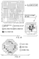
- Figure 9 depicts the bit located at (4, 2) in the classmap has been designated as the best pixel (see Segmentation 220). When these coordinates are multiplied by the respective scale factors (two for both coordinates in this example), the resulting bit is located at (8, 4)--designated in Figure 9 by a 'X'.
- a correction at a lower resolution 310 is opposite to a correction in a higher resolution 330 (i.e., each pixel in the lower resolution image contains information based on multiple pixels from the detect phase 200 image). Some of these detect phase 200 image pixels may be classified as eye color defect pixels while others may be classified as non-eye color defect pixels.
- the correction process here is substantially simpler than for up-scaling since no region growth refinement is needed to produce a more accurate class map.
- NxM For every NxM (where N equals the x-scale factor and M equals the y-scale factor ) grouping of pixels in the original detection phase 190 image, there corresponds a single lower resolution pixel. Since each pixel in the NxM pixel grouping is not guaranteed to be a eye color defect pixel, the corresponding lower resolution pixel may not possess the necessary characteristics to be termed a eye color defect candidate pixel by the detection phase 200. This is a problem. For a program to correct only the parts of a lower resolution pixel which are derived from true eye color defect candidates of the original resolution image, correct each lower resolution pixel by a percentage of the full correction. This percentage can be derived by knowing the number of eye color defect candidates contained within each NxM grouping of original image pixels.
- Figure 10 shows a classmap bit map and its corresponding scaledClassMap bit map. Again, to simply scale each bit in the classmap by the corresponding x-/y-scale factors to arrive at the scaledClassMap would over-estimate the number of pixels contained within an eye color defect. Furthermore, these pixels would be over corrected.
- YCC space is a simple translation of RGB space.
- R, G, and B represent the gamma-metric red, green, and blue coordinates of a given pixel
- Y, C1, and C2 represent the luminance, chroma-channel 1, and chroma-channel 2 coordinates of the pixel in YCC space.
- both chroma channels are zeroed out (i.e., only the pixel's neutral value is left).
- the luminance channel is multiplied by a factor of 0.35 in order to reduce the lightness of the pixel's neutral value.
- a red eye has an unusually high luminance value due to the over abundance of light produced by the flash of the camera which illuminates the retina. Thus, upon correction, a reduction of this high luminance value is required.
- Body correction 350 This is the method by which body pixels--pixels which are 8-connected only to eye color defect pixels--are desaturated (see Figure 11). Border correction 360 is performed on border pixels, pixels which are 8-connected to at least one non-eye color defect pixel and to at least one eye color defect pixel. Such pixels are only darkened by a 0.15 factor. Furthermore, those pixels which are considered to be associated with the glints of a eye color defect are sometimes found to contain subtle red hues.
- glint pixels Those pixels which: (1) are not eye color defect pixels, (2) are within 40% of the pupil's calculated radius from the pupil's centroid, and (3) have hue values which range from 600 and 1100, inclusive, are termed glint pixels.
- Glint correction 340 the chroma channels of glint pixels are zeroed out, while their luminance is left unchanged.
Landscapes
- Engineering & Computer Science (AREA)
- Multimedia (AREA)
- Signal Processing (AREA)
- Computer Vision & Pattern Recognition (AREA)
- Health & Medical Sciences (AREA)
- General Health & Medical Sciences (AREA)
- Ophthalmology & Optometry (AREA)
- Human Computer Interaction (AREA)
- Physics & Mathematics (AREA)
- General Physics & Mathematics (AREA)
- Theoretical Computer Science (AREA)
- Image Processing (AREA)
- Image Analysis (AREA)
- Exposure Control For Cameras (AREA)
- Stroboscope Apparatuses (AREA)
- Studio Circuits (AREA)
- Color Image Communication Systems (AREA)
Abstract
Description
- The present invention relates to digital detection for eye color defects of a subject in a digital image.
- In color flash photography a phenomenon know as red eye can occur. The term "red eye" refers to a person's photographically reproduced pupil(s) when they appear red instead of their normal black coloration. [This effect also occurs in flash photography of animals, although the characteristic color may not be red.] The reddish colored light is the result of the light produced by the flash reflecting off the eye's layer immediately behind the retina. To prevent this problem two procedures have been used during image capture: (1) increase the ambient light levels or (2) separate the flash from the camera by several inches. The first solution reduces the size of the pupil thus reducing the quantity of light reflected and also lessens the amount of required flash illumination. The second measure prevents the lens from detecting the reflected light since it is confined to a narrow beam directed back towards its source--the flash. Unfortunately the amateur photographer is not always in a position to execute either of the above solutions. In general the amateur uses a flash to account for the location's lack of ambient light. In addition, many point-and-shoot cameras, as well as some SLR's, have the flash located closely to the lens.
- After the image has been digitally captured it is possible to correct the eye color defects. Commonly assigned U.S. Patent No. 5,130,789 issued July 14, 1992 entitled "Localized Image Recoloring Using Ellipsoid Boundary Function" to Dobbs et al, describes a method by which a region's chroma and luma channels are modified after an operator identifies a region surrounding an eye.
- It is an object of this invention to automatically determine a defective colored eye in an image.
- It is another object of this invention to improve the correction by providing separate corrections for body, border, and glint pixels; and also provide for performing correction at different resolutions than that of detection.
- One of the preferred methods of the present invention is a method of detecting for eye color defects of a subject in an image due to flash illumination, comprising the steps of:
- a) defining a spatial region within which one or more eye color defects may exist, which region includes at least a portion of the subject's head;
- b) sampling pixels within such spatial region for their color content and comparing each such sampled pixel with a plurality of threshold values which are representative of eye color defects to identify possible eye color defective pixels;
- c) segmenting the identified possible eye color defect pixels into one or more spatially contiguous groups;
- d) calculating a first score for each pixel of each segmented group and for each group based upon a plurality of features including group size, group shape, coloration, and brightness to identify eye color defect group candidates;
- e) selecting a seed pixel based on its score from each identified eye color defect group candidate and determining all the neighboring pixels which are within a predetermined score range of their neighboring pixels and those pixels in a group which represent a significant pixel score transition so that the determined transitions identify the outer boundary of a eye color defect group candidate; and
- f) calculating a second score for each pixel for each eye color defect group candidate based on a plurality of features including group size, group shape, coloration, and brightness to determine an eye color defect group.
- The method used by the present invention maintains the '789 patent criterion of recoloration without destroying the region's luma fluctuation. However, the present invention automatically supplies two of the three inputs necessary to perform the disclosure of the '789 patent. Only the general region of interest is required at the beginning of the present invention as opposed to the more precise region requirements of the '789 patent. Also note that the present invention divides each pupil into three pixel categories: (1) body pixels, (2) border pixels, and (3) glint pixels. Each of these pixel types is treated differently in order to create a more natural appearing correction. Furthermore the image resolution from which the region of interest was obtained does not necessarily need to be the resolution at which the present invention corrects.
- The present invention is effective to detect eye color defects due to flash illumination and has the advantages of:
- (1) minimizing operator intervention,
- (2) achieving more accurate eye color defect corrections than was heretofore possible,
- (3) allowing for eye color defects to be detected at one image resolution while the correction process takes place in another image resolution, and
- (4) sub-dividing the eye color defect pixels into three categories (body, border, and glint) in order to render a more natural appearing eye.
-
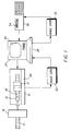
- Figure 1 illustrates a system in which the present invention is embodied;
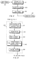
- Figure 2 illustrates a top level flow diagram of certain aspects of the present invention;
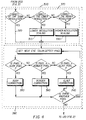
- Figure 3 illustrates a detailed flow diagram of the detection phase of Figure 2;
- Figure 4 illustrates a detailed flow diagram of the fix phase of Figure 2;
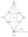
- Figure 5 illustrates the hue, lightness, and saturation space which is used in accordance with the present invention;
- Figures 6a-6c illustrate the Hue, Lightness, Saturation trapezoidal scoring used in the
First Scoring stage 230 of Figure 3 and in theSecond Scoring stage 250 shown in Figure 3; - Figure 7 illustrates Area trapezoidal scoring used in the present invention;
- Figures 8a and 8b illustrate 45° trapezoidal scoring used in the present invention;
- Figure 9 illustrates an example of the scaling up method shown in the
Correcting stage 380 shown in Figure 4; - Figure 10 illustrates an example of the scaling down method outlined in the
Correcting stage 380 of Figure 4; and - Figure 11 illustrates an example eye color defect whereby each pixel of the eye color defect is deemed as either a: body pixel, border pixel, or glint pixel.
- Referring to Figure 1, the present invention is implemented using a
digitizing scanner 10, a control andlogic device 24, such as a computer with adisplay device 26, and anoptical disc writer 36. As shown, a strip offilm 15, containing one ormore frames 18 of developed film, is placed into ascan gate 12 where the strip offilm 15 is scanned under direction of control andlogic circuitry 30. As eachframe 18 is scanned the resultant image data, represented byblock 22, is digitized and transmitted to amemory 28 for storage. Thecomputer 24 process the stored data, in a manner to be described, to provideoutput image data 32 which may be written to anoptical disc 34 by theoptical disc writer 36 to provide a report as to the characteristics of the anomalies. The digitizedscanner 10 is capable of quantizing pixel values into multiple brightness levels in separate red, green, and blue channels. A minimum number of brightness levels would be approximately 64 for an adequate quality image with a typical number being 256. Although theimage data 32 has been described as originating from the operation of scanning film, it is well understood that other well known techniques may be used to provide the image data. - The
computer 24 operates the present invention. Referring now to Figure 2, this invention can be broken down into two distinct phases: (1) thedetection phase 200 and (2) thefix phase 300. Thedetection phase 200 can be broken down into five distinct stages (see Figure 3): (1) identification of eye colordefect candidate pixels 210, (2)segmentation 220, (3)first scoring 230, (4) region growth (or pixel score transition identification) 240, and (5)second scoring 250. Each stage of thedetection phase 200 accesses the results produced by the previous stage creating a data processing chain. Thefix phase 300 can be broken down into two sections (see Figure 4): (1) scaling 370 and (2) correcting 380. The resolution section can in turn be broken down into three stages: (1)lower resolution 310, (2)same resolution 320, and (3)higher resolution 330. The correction section can also be broken down into three stages: (1)glint correction 340, (2)body correction 350, and (3)border correction 360. - It is important to note the necessity of this data processing chain. In the case of red eye defects if one were simply to assume that all reddish pixels in an image were defects, then numerous non-red eye pixels would be included with the set of true red eye pixels. Red eye is comprised of both color and spatial cues. To depend on one, but not the other set of cues, will produce incorrect results. It is the building up of clues, produced by each stage in the data processing chain, which allows the present invention to discern between red eye and non-red eye pixels.
- What makes red eye so noticeable and distracting to a viewer is the concentration of red elements (e.g., pixels on a CRT) surrounded by non-red elements. An elements' coloration is determined by its combination of the red, green, and blue characterizing values. Therefore, one could conclude that the elements which comprise a red eye region contain more red than green or blue. In fact, experimental results show red eye pixels to observe, on average, a 1.7:1 red to maximum (green, blue) intensity ratio in the video gamma metric. By increasing/decreasing this ratio the invention decreases/increases its sensitivity to red.
- By converting an element's RGB values to HLS (hue, lightness, and saturation) space, see Figure 5, one can derive the kind of red observed in flash illuminated human eyes. The following derived values are those used in an existing implementation, but may be adjusted to modify the sensitivity of the present invention:
700 ≦ Hue ≦ 1010
40 ≦ Luma ≦ 166
65 ≦ Saturation ≦ 256
Therefore the ratio and the 3-dimensional HLS region comprise the criteria used in the first stage of the present invention. Any pixel in the given image which adheres to these criteria is represented as a one in a pre-zeroed out bit map, the color bit map. A bit map is a section of memory which holds ones or zeros. This binary data can represent many things depending on the program which interprets it. In the present invention, the bit maps represent pixels which are eye color defect pixel candidates. Since these maps use only a single bit to represent a piece of data, this data structure can save vast amounts of physical memory. Thus, at the end of this stage only those pixels which pass the above criteria are represented in the color bit map. For a detailed discussion of hue, lightness, and saturation space see Computer Graphics: A Quarterly Report of SIGGRAPH--ACM, Vol. 13, No. 3, Aug. 1979, pp. III - 37 & 38. - Up to this stage the present invention has been working on individual pixels; eliminating those which did not meet the Identification of Eye Color Defect Candidate Pixels stage 210 criteria in Figure 3. It is now time to group these pixels into spatially contiguous groups, termed segments.
- The process begins by raster scanning the color bit map until a non-zeroed bit is encountered. This bit is the seed bit. Once found, the seed bit is set to one in the pre-zeroed marked bit map. Next, the segmentor enters a loop which terminates when no bits are "on" in the marked bit map. The first step of the loop is to zero out the current bit in the color bit map. Next, a function is called which searches (in 8-connected fashion) around the current bit in the color bit map for "on" bits. As "on" bits are found, they are placed into the marked bit map if and only if they are not also "on" in the seed bit map. Once all 8-connected "on" bits have been found, the function returns to the segmentor loop. The next step of the loop is to zero out the current bit in the marked bit map and turn "on" the current bit in the seed bit map. Finally, a function is called which searches the marked bit map for the top left non-zeroed bit. This bit now becomes the current bit and the loop cycles again. Eventually the segmentor loop terminates. At this point each segment is validated based on area and shape. Specifically, there are two criteria, eccentricity and number of pixels. The eccentricity of a segment must be greater than a minimum eccentricity and less than a maximum eccentricity, where 0.0 is perfectly round and 1.0 is maximally elongated (i.e., a line). This range of eccentricity values eliminates linear segment types (i.e., pupils are roundish). See Appendix A for the current equations used to implement an eccentricity value. A segment must contain a predetermined minimum and maximum area (in pixels). A segment with fewer than the minimum number of pixels is generally indistinguishable from other image objects (e.g., a patch of skin). If validated, then this segment is entered into the classmap bit map. The zeroing out of the seed bit map ends this part of the segmentor. Before continuing, it is crucial that the reader understand that only two of the four bit maps, the color and classmap bit maps, could currently contain "on" bits. The color bit map might contain "on" bits which belong to other segments, and the classmap bit map can only contain those segments previously found and the current segment.
- Lastly, the raster scan of the color bit map continues. When the next non-zeroed bit in the color bit map is encountered it is designated as the seed bit and the process begins anew. This continues until there are no "on" bits in the color bit map.
- As a segment is classified, two tasks are performed: (1) insertion of the new segment into the classmap bit map and (2) compilation of data on the segment is accumulated. This data includes eccentricity, a measure of a segment's circular nature; the number of pixels contained within the segment (i.e., area); the segment's score; the best pixel score (i.e., the largest pixel score occurring in the segment); the best pixel's coordinates; and the coordinates of the segment's centroid. Each segment found has its corresponding statistics saved so that the following stages may access them.
- A continuous-weighting approach to scoring a pixel is taken in the present invention. Various criteria (hue, lightness, saturation, and the ratio test) are taken into consideration and based upon them an eye color defect score is given. Scores range from zero to one, inclusive.
- In the present invention a pixel is scored based on its HLS values and whether or not the pixel passes the ratio criterion (i.e., a bi-value score). Each pixel in an image contains a hue, lightness, and saturation value. Given these values a score for each of these channels can be calculated (scorehue, scorelightness, and scoresaturation). These scores are produced based on the information presented in Figures 6a-6c. A score for a given channel value equals the corresponding trapezoidal weighting function for that value. Next read the score off the y-axis. For example, if a given pixel has the following HLS values:
H = 73,
L = 75,
S = 68,
then the corresponding scores would be:
scorehue = 0.5
scorelightness = 1.0
scoresaturation = 0.032.
In pseudo-code, a score is calculated by:
if (valuep < value₁) then
score = 0.0
else if(valuep > value₄) then
score = 0.0
else if(value₁ ≦ valuep < value₂) then
score = (valuep - value₁)/(value₂ - value₁)
else if(value₃ < valuep ≦ value₄) then
score = (valuep - value₄)/(value₃ - value₄);
where valuep is the channel (hue, lightness, or saturation) of the pixel in question, value₁ represents the first point of the trapezoid (h1, l1, or s1), value₂ represents the second point (h2, l2, or s2), value₃ represents the third point (h3, l3, or s3), and value₄ represents the fourth point (h4, l4, or s4). Lastly, these three scores are multiplied together producing a final pixel score ranging from 0.0 to 1.0, inclusive. - The purpose for multiplying individual channel scores together is so that if a pixel fails a channel test (falls outside the trapezoidal region), then that pixel will receive an overall score of zero (i.e., not a eye color defect candidate). Also, a very large score in one channel can partially compensate for low--but acceptable--scores in the other channels.
- A segment's score is determined by calculating the average score of the pixels contained within it.
- The
Region Growth stage 240 is a process for cleaning up segments by eliminating questionable sub-regions which passed the color threshold tests but appear to have unlikely spatial variations. - Digital imaging region growth is a method by which pixels are annexed to a region's already existing pixels. This is analogous to the growth of crystals. For a crystal to begin growing, a piece of dust (or some other material) must exist. Then, as a solution is introduced, some of the dissolved particles precipitate out of solution and begin forming the crystal structure. Growth ends when the particles in the solution drop below a certain concentration. In a similar way, the growth of a digital region begins with a supplied seed pixel and ends when the connected pixels no longer meet the defined criteria of similarity. A segment's seed pixel is obtained during the
Segmentation stage 220. This pixel is designated as the coordinates of the best pixel in a given segment. - To start, the Region Growth stage 240 loops through each segment found in the
Segmentation stage 220. As described above, each segment contains a best pixel. This pixel is the seed pixel. The method searches (in an 8-connected pattern) around the current pixel and locates all pixels which have scores that are:
scorecurrent pixel - 0.5 ≦ scoreneighboring pixel
scoreneighboring pixel ≧ scorecurrent segment
Those neighboring pixels which pass one or both of the above two criteria are annexed to the growing region. Only those pixels which were part of the segment, after theSegmentation stage 220, are considered during this stage. This process of annexing pixels continues for each segment until no old segment pixels are left to be verified. - Since the resultant segments from this stage may differ from those of the Segmentation stage 220 (i.e., pixels may have been dropped from the segment's make up), new segment statistics and scores are updated 250.
- At this point there is nothing more to do than assume that the segment with the best score is an eye color defect, termed the primary eye (or primary eye segment). If more than one eye is expected in the image window, then an additional search is conducted for other eye color defects, termed secondary eyes (or secondary eye segments). Based on the primary eye segment's area (or number of pixels) and the 45° criteria, a new score is calculated for the other defective eye segment candidates. [The 45° criteria mandates that the secondary eye must be located somewhere within ± 45° of the horizontal, which runs through the centroid of the primary eye (see Figures 8a and 8b). Any segments which are not in this area are given scores of zero (i.e., are not considered to be secondary eye candidates).] The area score (scorearea) is determined based on the triangular weighting function presented in Figure 7. As with the previous scoring methods, the area scores range from 0.0 to 1.0, inclusive. This scorearea and the score₄₅ are multiplied to the score of the segment in question, in order to arrive at the segment's new score. The segment with the top remaining score is assumed to be the secondary eye.
- A very important feature of the present invention centers around the
fix phase 300 and its flexibility. By this phase the classmap bit map should contain the eye color defects within the image. Now, the invention must replace each eye color defect with a natural appearing pupil. To accomplish this rendering two important issues must be investigated: (1) scaling 370, and (2) correcting 380. - The flexibility alluded to above involves the interdependencies of the
detection phase 200 with thefix phase 300. One might wish to perform thedetection phase 200 in some image resolution, but perform thefix phase 300 in another. To account for this flexibility, theScaling section 370, in Figure 4, is subdivided into three sections: (1) fixing at thesame resolution 320 as detection, (2) fixing at ahigher resolution 330, and (3) fixing at alower resolution 310. Each of these sections is handled differently. To fix at thesame resolution 320 requires no added classmap bit map handling. All that is needed is to correct each pixel which is represented in the classmap bit map (see Correcting below). To fix at higher or lower resolutions requires the creation of a new bit map, the scaledClassMap. - The problem when correcting at a
higher resolution 330, is that each pixel in the classmap actually has contributions from several pixels at the higher resolution. Some of these pixels may be eye color defect pixels, but others may not. Thus, a refined eye color defect selection process must be performed at the higher resolution. - The process of fixing an image at a higher resolution entails the formation of a scaled up version of the classmap bit map. The first step of the process is to pass the scaled version of the original image (the image which the
detection phase 200 worked on) to the Identification of Eye Color DefectCandidate Pixels stage 210. This stage returns a scaledColor bit map. Next, each segment contained within the classmap bit map is examined. As each segment is encountered its best pixel's coordinates are scaled up by the appropriate x-/y-scale factors. In theory these coordinates will be at most ± the x-/y-scale factor number of coordinates away from the original coordinates multiplied by their scale factor value, respectively. For example, if an image contained one eye color defect and the present invention correctly detected it, then the classmap bit map shown in the upper left-hand corner of Figure 9 would be the result. Furthermore, if the user requested that thefix phase 300 be performed on the image scaled by 2 (in both the x and y directions), then the scaledColor bit map shown in the lower-right corner of Figure 9 would be the result. Figure 9 depicts the bit located at (4, 2) in the classmap has been designated as the best pixel (see Segmentation 220). When these coordinates are multiplied by the respective scale factors (two for both coordinates in this example), the resulting bit is located at (8, 4)--designated in Figure 9 by a 'X'. Unfortunately this bit location is not classified as a eye color defect candidate in the scaledColor bit map. Therefore, a search is undertaken to find the closest eye color defect candidate in the scaledColor bit map. Once found, this location is used as the seed point for theSegmentation stage 220. Finally theRegion Growth stage 240 is invoked and a valid class map bit map, the scaledClassMap, is produced. All that is left now is to correct the pixels in the scaled version of the original image which are categorized as eye color defect pixels in the scaledClassMap bit map (see Correction below). The above outlined methodology does not simply scale up the classmap bit map. If one were to replace every bit in the lower resolution with N (where N equals x-scale factor time y-scale factor) number of bits, then the resulting class map, the scaledClassMap, would over-estimate the true number of pixels contained within the eye color defect. - A correction at a
lower resolution 310 is opposite to a correction in a higher resolution 330 (i.e., each pixel in the lower resolution image contains information based on multiple pixels from the detectphase 200 image). Some of these detectphase 200 image pixels may be classified as eye color defect pixels while others may be classified as non-eye color defect pixels. The correction process here is substantially simpler than for up-scaling since no region growth refinement is needed to produce a more accurate class map. - For every NxM (where


detection phase 200. This is a problem. For a program to correct only the parts of a lower resolution pixel which are derived from true eye color defect candidates of the original resolution image, correct each lower resolution pixel by a percentage of the full correction. This percentage can be derived by knowing the number of eye color defect candidates contained within each NxM grouping of original image pixels. Figure 10 shows a classmap bit map and its corresponding scaledClassMap bit map. Again, to simply scale each bit in the classmap by the corresponding x-/y-scale factors to arrive at the scaledClassMap would over-estimate the number of pixels contained within an eye color defect. Furthermore, these pixels would be over corrected. - Pupils which exhibit the red eye phenomenon differ from normal pupils in that they are reddish in hue (rather than neutral), and are brighter. Correction is generally accomplished by removing a pixel's chromaticity and darkening its luminance. To perform this task, a given pixel's gamma RGB values are converted to YCC values. [YCC space is a simple translation of RGB space. To transform an image in RGB space to YCC space, multiply each pixel by the following matrix:

where R, G, and B represent the gamma-metric red, green, and blue coordinates of a given pixel, and Y, C1, and C2, represent the luminance, chroma-channel 1, and chroma-channel 2 coordinates of the pixel in YCC space. The gamma RGB and the YCC color metrics are described in the KODAK PhotoCD Products: A Planning Guide for Developers, Eastman Kodak Company, 1992 (part no. DCI200R).] Next, both chroma channels are zeroed out (i.e., only the pixel's neutral value is left). At this point, the luminance channel is multiplied by a factor of 0.35 in order to reduce the lightness of the pixel's neutral value. (In general, a red eye has an unusually high luminance value due to the over abundance of light produced by the flash of the camera which illuminates the retina. Thus, upon correction, a reduction of this high luminance value is required. This factor, 0.35, is based upon experimental evidence and other values may result in natural renderings.) Finally, the YCC values are converted back to gamma RGB values, and set as the pixel's values. The above procedure describesBody correction 350. This is the method by which body pixels--pixels which are 8-connected only to eye color defect pixels--are desaturated (see Figure 11).Border correction 360 is performed on border pixels, pixels which are 8-connected to at least one non-eye color defect pixel and to at least one eye color defect pixel. Such pixels are only darkened by a 0.15 factor. Furthermore, those pixels which are considered to be associated with the glints of a eye color defect are sometimes found to contain subtle red hues. Those pixels which: (1) are not eye color defect pixels, (2) are within 40% of the pupil's calculated radius from the pupil's centroid, and (3) have hue values which range from 600 and 1100, inclusive, are termed glint pixels. To performGlint correction 340, the chroma channels of glint pixels are zeroed out, while their luminance is left unchanged. - This invention has been described with reference to correcting "red eye" defects, but those skilled in the art will recognize that it is also applicable for correcting for eye color defects in animals, but that different detection and correction values specific to the subject's defective color should be used. Moreover, although two specific color spaces have been used, others will suggest themselves to those skilled in the art.
-
- 10
- digitized scanner
- 12
- scan gate
- 15
- film
- 18
- frames
- 22
- block
- 24
- control & logic device (computer)
- 26
- display device
- 28
- memory
- 30
- logic circuitry
- 32
- image data
- 34
- optical disc
- 36
- disc writer
- 200
- detection phase
- 210
- defect candidate pixels
- 220
- segementation stage
- 230
- first scoring stage
- 240
- region growth stage
- 250
- second scoring
- 300
- fix phase
- 310
- lower resolution
- 320
- same resolution
- 330
- higher resolution
- 340
- glint correction
- 350
- body correction
- 360
- border correction
- 370
- scaling logic
- 380
- correcting logic
Claims (25)
- A method of detecting for eye color defects of a subject in a digital image due to flash illumination, comprising the steps of:a) defining a spatial region within the digital image in which one or more eye color defects may exist, which region includes at least a portion of the subject's head;b) sampling pixels within such spatial region for their color content and comparing each such sample pixel with a plurality of threshold values which are representative of eye color defects to identify possible eye color defect pixels;c) segmenting the identified possible eye color defective pixels into one or more spatially contiguous groups;d) calculating a first score for each pixel of each segmented group and for each group based upon a plurality of features including group size, group shape, coloration, and brightness to identify eye color defect group candidates;e) selecting a seed pixel based on its score from each identified eye color defect group candidate and determining all the neighboring pixels which are within a predetermined score range of their neighboring pixels and those pixels in a group which represent a significant pixel score transition so that the determined transitions identify the outer boundary of an eye color defect group candidate; andf) calculating a second score for each pixel for each eye color defect group candidate based on a plurality of features including group size, group shape, coloration, and brightness to determine an eye color defect group.
- The method of claim 1 further including correcting of the defective color in each eye color defect group.
- The method of claim 2 wherein the threshold value represents minimum and maximum allowed values consistent with the expected color of a eye color defect group.
- The method of claim 1 wherein the group size feature is area, the group shape feature is eccentricity, the coloration and brightness features are hue, saturation, lightness, and red to maximum (green, blue) ratio.
- The method of claim 1 wherein the scores per pixel in steps d) and f) are equal to the product of the scores of individual features, and the scores of individual features are weighted functions of the feature values of the pixels.
- The method of claim 5 wherein the group score is an average of all the pixels.
- A method of detecting for eye color defects of a subject in a digital image due to flash illumination, comprising the steps of:a) defining a spatial region within the digital image in which one or more eye color defects may exist, which region includes at least a portion of the subject's head;b) sampling pixels within such spatial region for their color content and comparing each such sampled pixel with a plurality of threshold values which are representative of eye color defects to identify possible eye color defect pixels;c) segmenting the identified possible eye color defect pixels into one or more spatially contiguous groups;d) calculating a first score for each pixel of each segmented group and for each group based upon a plurality of features including group size, group shape, coloration, and brightness to identify eye color defect group candidates;e) selecting a seed pixel based on its score from each identified eye color defect group candidate and determining all the neighboring pixels which are within a predetermined score range of their neighboring pixels and those pixels in a group which represent a significant pixel score transition so that the determined transitions identify the outer boundary of an eye color defect group candidate;f) calculating a second score for each pixel for each eye color defect group candidate based on a plurality of features including group size, group shape, coloration, and brightness to determine an eye color defect group;g) selecting the best group score of an eye color defect group candidate and comparing it relative to a predetermined threshold group score to determine whether an eye is present and identify the most likely eye; andh) determining whether another eye color defect group is present based on whether the area of that eye is within a predetermined threshold ratio of the area of the color defect group corresponding to the most likely eye, and whether this group must be within a predetermined threshold angular subtense of the most likely eye along the predetermined horizontal axis of the subject's head.
- The method of claim 7 further including correcting of the defective color in each eye color defect group.
- The method of claim 8 wherein the threshold value represents minimum and maximum allowed values consistent with the expected color of a eye color defect group.
- The method of claim 7 wherein the group size feature is area, the group shape feature is eccentricity, the coloration and brightness features are hue, saturation, lightness, and red to maximum (green, blue) ratio.
- The method of claim 7 wherein the scores per pixel in steps d) and f) are equal to the product of the scores of individual features, and the scores of individual features are weighted functions of the feature values of the pixels.
- The method of claim 11 wherein the group score is an average of all the pixels.
- A method of detecting and correcting for eye color defects of a subject in a digital image due to flash illumination, comprising the steps of:a) defining a spatial region within the digital image in which one or more eye color defects may exist, which region includes at least a portion of the subject's head;b) sampling pixels within such spatial region for their color content and comparing each such sampled pixel with a plurality of threshold values which are representative of eye color defects to identify possible eye color defect pixels;c) segmenting the identified possible eye color defect pixels into one or more spatially contiguous groups;d) calculating a first score for each pixel of each segmented group and for each group based upon a plurality of features including group size, group shape, coloration, and brightness to identify eye color defect group candidates;e) selecting a seed pixel based on its score from each identified eye color defect group candidate and determining all the neighboring pixels which are within a predetermined score range of their neighboring pixels and those pixels in a group which represent a significant pixel score transition so that the determined transitions identify the outer boundary of an eye color defect group candidate;f) calculating a second score for each pixel for each eye color defect group candidate based on a plurality of features including group size, group shape, coloration, and brightness to determine an eye color defect group;g) selecting the best group score of an eye color defect group candidate and comparing it relative to a predetermined threshold group score to determine whether an eye is present and identify the most likely eye; andh) determining whether another eye color defect group is present based on whether the area of that eye is within a predetermined threshold ratio of the area of the color defect group corresponding to the most likely eye, and whether this group must be within a predetermined threshold angular subtense of the most likely eye along the predetermined horizontal axis of the subject's head;i) correcting the defective color in each eye color defect group by:(i) determining the correct resolution and whether each pixel at the corrected resolution is an eye color defect pixel;(ii) categorizing the eye color defect pixels at the corrected resolution into either body, border, or glint categories; and(iii) correcting the eye color defect pixels in the body, border, or glint categories.
- The method of claim 13 wherein the threshold value represents minimum and maximum allowed values consistent with the expected color of a eye color defect group.
- The method of claim 13 wherein the group size feature is area, the group shape feature is eccentricity, the coloration and brightness features are hue, saturation, lightness, and red to maximum (green, blue) ratio.
- The method of claim 13 wherein the scores per pixel in steps d) and f) are equal to the product of the scores of individual features, and the scores of individual features are weighted functions of the feature values of the pixels.
- The method of claim 16 wherein the group score is an average of all the pixels.
- The method of claim 13 wherein step i) (i) includes determining at a lower resolution a correction factor for each low resolution pixel which is a function of the number of eye color defect pixels at the original resolution disposed at the same image location.
- The method of claim 13 wherein step i) (i) includes categorizing at a higher resolution each original eye color defect pixel into eye color defect pixels and non-eye color defect pixels.
- The method of claim 13 including desaturating and reducing the illuminance for each body, border, and glint pixel.
- A method of correcting eye color defects of a subject in an image due to flash illumination, comprising the steps of:a) providing the location of each eye color defect pixel in the subject's eye; andb) correcting the defective color in each eye color defect pixel as a function of whether the corrected resolution will be at a higher or lower resolution.
- The method of claim 21 which includes determining at a lower resolution a scale factor for each low resolution pixel which is a function of the number of eye color defect pixels at the original resolution disposed at the same image location.
- The method of claim 21 which includes categorizing at a higher resolution each original eye color defect pixel into eye color defect pixels and non-eye color defect pixels.
- Apparatus for detecting for eye color defects of a subject in an image due to flash illumination, comprising the steps of:a) means for scanning an image containing the subject in a medium to produce a digital image;b) means for defining a spatial region within such digital image wherein one or more eye color defects may exist, which region includes at least a portion of the subject's head;c) means for sampling pixels within such spatial region for their color content and comparing each such sampled pixel with a plurality of threshold values which are representative of eye color defects to identify possible eye color defect pixels;d) means for segmenting the identified possible eye color defect pixels into one or more spatially contiguous groups;e) means for calculating a first score for each pixel of each segmented group and for each group based upon a plurality of features including group size, group shape, coloration, and brightness to identify eye color defect group candidates;f) means for selecting a seed pixel based on its score from each identified eye color defect group candidate and determining all the neighboring pixels which are within a predetermined score range of their neighboring pixels and those pixels in a group which represent a significant pixel score transition so that the determined transitions identify the outer boundary of an eye color defect group candidate;g) means for calculating a second score for each pixel for each eye color defect group candidate based on a plurality of features including group size, group shape, coloration, and brightness to determine an eye color defect group;h) means for selecting the best group score of an eye color defect group candidate and comparing it relative to a predetermined threshold group score to determine whether an eye is present and identify the most likely eye; andi) means for determining whether another eye color defect group is present based on whether the area of that eye is within a predetermined threshold ratio of the area of the color defect group corresponding to the most likely eye, and whether this group must be within a predetermined threshold angular subtense of the most likely eye along the predetermined horizontal axis of the subject's head.
- Apparatus for detecting and correcting for eye color defects of a subject in an image due to flash illumination, comprising the steps of:a) means for scanning an image containing the subject in a medium to produce a digital image;b) means for defining a spatial region within which one or more eye color defects may exist, which region includes at least a portion of the subject's head;c) means for sampling pixels within such spatial region for their color content and comparing each such sampled pixel with a plurality of threshold values which are representative of eye color defects to identify possible eye color defect pixels;d) means for segmenting the identified possible eye color defect pixels into one or more spatially contiguous groups;e) means for calculating a first score for each pixel of each segmented group and for each group based upon a plurality of features including group size, group shape, coloration, and brightness to identify eye color defect group candidates;f) means for selecting a seed pixel based on its score from each identified eye color defect group candidate and determining all the neighboring pixels which are within a predetermined score range of their neighboring pixels and those pixels in a group which represent a significant pixel score transition so that the determined transitions identify the outer boundary of an eye color defect group candidate;g) means for calculating a second score for each pixel for each eye color defect group candidate based on a plurality of features including group size, group shape, coloration, and brightness to determine an eye color defect group;h) means for selecting the best group score of an eye color defect group candidate and comparing it relative to a predetermined threshold group score to determine whether an eye is present and identify the most likely eye; andi) means for determining whether another eye color defect group is present based on whether the area of that eye is within a predetermined threshold ratio of the area of the color defect group corresponding to the most likely eye, and whether this group must be within a predetermined threshold angular subtense of the most likely eye along the predetermined horizontal axis of the subject's head;j) means for correcting the defective color in each eye color defect group by:(i) determining the correct resolution and whether each pixel at the corrected resolution is an eye color defect pixel;(ii) categorizing the eye color defect pixels at the corrected resolution into either body, border, or glint categories; and(iii) correcting the eye color defect pixels in the body, border, or glint categories.
Applications Claiming Priority (2)
| Application Number | Priority Date | Filing Date | Title |
|---|---|---|---|
| US93843 | 1979-11-13 | ||
| US08/093,843 US5432863A (en) | 1993-07-19 | 1993-07-19 | Automated detection and correction of eye color defects due to flash illumination |
Publications (3)
| Publication Number | Publication Date |
|---|---|
| EP0635972A2 true EP0635972A2 (en) | 1995-01-25 |
| EP0635972A3 EP0635972A3 (en) | 1995-09-27 |
| EP0635972B1 EP0635972B1 (en) | 1999-01-13 |
Family
ID=22241139
Family Applications (1)
| Application Number | Title | Priority Date | Filing Date |
|---|---|---|---|
| EP94201902A Expired - Lifetime EP0635972B1 (en) | 1993-07-19 | 1994-07-01 | Automated detection and correction of eye color defects due to flash illumination |
Country Status (4)
| Country | Link |
|---|---|
| US (2) | US5432863A (en) |
| EP (1) | EP0635972B1 (en) |
| JP (1) | JP3181472B2 (en) |
| DE (1) | DE69415886T2 (en) |
Cited By (19)
| Publication number | Priority date | Publication date | Assignee | Title |
|---|---|---|---|---|
| EP0884694A1 (en) * | 1997-05-30 | 1998-12-16 | Adobe Systems, Inc. | Adjusting color in digital images |
| EP0899686A2 (en) | 1997-08-29 | 1999-03-03 | Eastman Kodak Company | A computer program product for redeye detection |
| WO1999017254A1 (en) * | 1997-09-26 | 1999-04-08 | Polaroid Corporation | Digital redeye removal |
| EP0911759A2 (en) * | 1997-10-23 | 1999-04-28 | Hewlett-Packard Company | apparatus and a method for reducing red-eye in an image |
| WO1999038121A1 (en) * | 1998-01-27 | 1999-07-29 | Sensar, Inc. | Method and apparatus for removal of bright or dark spots by the fusion of multiple images |
| EP0961225A2 (en) * | 1998-05-26 | 1999-12-01 | Eastman Kodak Company | A computer program product for redeye detection |
| EP1229734A1 (en) * | 2001-01-31 | 2002-08-07 | GRETAG IMAGING Trading AG | Automatic colour defect correction |
| EP1288860A1 (en) * | 2001-09-03 | 2003-03-05 | Agfa-Gevaert AG | Method for processing digital photographic image data including a method for the automatic detection of red-eye defects |
| GB2379819A (en) * | 2001-09-14 | 2003-03-19 | Pixology Software & Systems | Image processing to remove red-eye features |
| GB2385736A (en) * | 2002-02-22 | 2003-08-27 | Pixology Software & Systems | Detection of red eye features in digital images by determination of the profile of image pixel values along a row of values |
| WO2003071781A1 (en) * | 2002-02-22 | 2003-08-28 | Pixology Software Limited | Detection and correction of red-eye features in digital images |
| EP1359740A1 (en) * | 2002-04-30 | 2003-11-05 | Agfa-Gevaert AG | System and method for processing images |
| US6792134B2 (en) | 2000-12-19 | 2004-09-14 | Eastman Kodak Company | Multi-mode digital image processing method for detecting eyes |
| WO2005022466A2 (en) * | 2003-08-29 | 2005-03-10 | Hewlett-Packard Development Company L.P. | Detecting and correcting redeye in an image |
| US6920237B2 (en) | 2000-12-19 | 2005-07-19 | Eastman Kodak Company | Digital image processing method and computer program product for detecting human irises in an image |
| FR2880969A1 (en) * | 2005-01-20 | 2006-07-21 | Sagem | Image`s red eye detecting method for digital image printing device, involves detecting skin region on image, producing mask comprising skin region, and detecting red eye in skin region |
| EP1734475A3 (en) * | 2005-06-14 | 2010-07-21 | Canon Kabushiki Kaisha | Detecting an image area having poor color tone |
| US8861845B2 (en) | 2003-08-29 | 2014-10-14 | Hewlett-Packard Development Company, L.P. | Detecting and correcting redeye in an image |
| EP2529354A4 (en) * | 2010-01-29 | 2015-09-16 | Hewlett Packard Development Co | Correcting an artifact in an image |
Families Citing this family (178)
| Publication number | Priority date | Publication date | Assignee | Title |
|---|---|---|---|---|
| JP3444552B2 (en) * | 1994-05-24 | 2003-09-08 | オリンパス光学工業株式会社 | Camera system |
| JP2907120B2 (en) * | 1996-05-29 | 1999-06-21 | 日本電気株式会社 | Red-eye detection correction device |
| US6233395B1 (en) | 1996-09-20 | 2001-05-15 | Covance Laboratories Gmbh | Method for quantitative iris colorimetry |
| US6786420B1 (en) | 1997-07-15 | 2004-09-07 | Silverbrook Research Pty. Ltd. | Data distribution mechanism in the form of ink dots on cards |
| US6381345B1 (en) * | 1997-06-03 | 2002-04-30 | At&T Corp. | Method and apparatus for detecting eye location in an image |
| US5990901A (en) * | 1997-06-27 | 1999-11-23 | Microsoft Corporation | Model based image editing and correction |
| US6009209A (en) * | 1997-06-27 | 1999-12-28 | Microsoft Corporation | Automated removal of red eye effect from a digital image |
| US6803989B2 (en) * | 1997-07-15 | 2004-10-12 | Silverbrook Research Pty Ltd | Image printing apparatus including a microcontroller |
| US6618117B2 (en) | 1997-07-12 | 2003-09-09 | Silverbrook Research Pty Ltd | Image sensing apparatus including a microcontroller |
| US6702417B2 (en) * | 1997-07-12 | 2004-03-09 | Silverbrook Research Pty Ltd | Printing cartridge with capacitive sensor identification |
| AUPO799997A0 (en) * | 1997-07-15 | 1997-08-07 | Silverbrook Research Pty Ltd | Image processing method and apparatus (ART10) |
| US6879341B1 (en) * | 1997-07-15 | 2005-04-12 | Silverbrook Research Pty Ltd | Digital camera system containing a VLIW vector processor |
| US7246897B2 (en) * | 1997-07-15 | 2007-07-24 | Silverbrook Research Pty Ltd | Media cartridge for inkjet printhead |
| US7705891B2 (en) * | 1997-07-15 | 2010-04-27 | Silverbrook Research Pty Ltd | Correction of distortions in digital images |
| US7551202B2 (en) * | 1997-07-15 | 2009-06-23 | Silverbrook Research Pty Ltd | Digital camera with integrated inkjet printer |
| US6690419B1 (en) | 1997-07-15 | 2004-02-10 | Silverbrook Research Pty Ltd | Utilising eye detection methods for image processing in a digital image camera |
| US6624848B1 (en) * | 1997-07-15 | 2003-09-23 | Silverbrook Research Pty Ltd | Cascading image modification using multiple digital cameras incorporating image processing |
| US20040160524A1 (en) * | 1997-07-15 | 2004-08-19 | Kia Silverbrook | Utilising exposure information for image processing in a digital image camera |
| US7714889B2 (en) * | 1997-07-15 | 2010-05-11 | Silverbrook Research Pty Ltd | Digital camera using exposure information for image processing |
| US7593058B2 (en) * | 1997-07-15 | 2009-09-22 | Silverbrook Research Pty Ltd | Digital camera with integrated inkjet printer having removable cartridge containing ink and media substrate |
| US7077515B2 (en) * | 1997-07-15 | 2006-07-18 | Silverbrook Research Pty Ltd | Media cartridge for inkjet printhead |
| US7110024B1 (en) * | 1997-07-15 | 2006-09-19 | Silverbrook Research Pty Ltd | Digital camera system having motion deblurring means |
| AUPO850597A0 (en) * | 1997-08-11 | 1997-09-04 | Silverbrook Research Pty Ltd | Image processing method and apparatus (art01a) |
| US7551201B2 (en) | 1997-07-15 | 2009-06-23 | Silverbrook Research Pty Ltd | Image capture and processing device for a print on demand digital camera system |
| US7738015B2 (en) | 1997-10-09 | 2010-06-15 | Fotonation Vision Limited | Red-eye filter method and apparatus |
| US7042505B1 (en) | 1997-10-09 | 2006-05-09 | Fotonation Ireland Ltd. | Red-eye filter method and apparatus |
| US7352394B1 (en) | 1997-10-09 | 2008-04-01 | Fotonation Vision Limited | Image modification based on red-eye filter analysis |
| US6407777B1 (en) * | 1997-10-09 | 2002-06-18 | Deluca Michael Joseph | Red-eye filter method and apparatus |
| US7630006B2 (en) | 1997-10-09 | 2009-12-08 | Fotonation Ireland Limited | Detecting red eye filter and apparatus using meta-data |
| US6160923A (en) * | 1997-11-05 | 2000-12-12 | Microsoft Corporation | User directed dust and compact anomaly remover from digital images |
| US6266054B1 (en) | 1997-11-05 | 2001-07-24 | Microsoft Corporation | Automated removal of narrow, elongated distortions from a digital image |
| US6631208B1 (en) * | 1998-05-29 | 2003-10-07 | Fuji Photo Film Co., Ltd. | Image processing method |
| AUPP702098A0 (en) | 1998-11-09 | 1998-12-03 | Silverbrook Research Pty Ltd | Image creation method and apparatus (ART73) |
| US6285410B1 (en) * | 1998-09-11 | 2001-09-04 | Mgi Software Corporation | Method and system for removal of flash artifacts from digital images |
| US6134339A (en) * | 1998-09-17 | 2000-10-17 | Eastman Kodak Company | Method and apparatus for determining the position of eyes and for correcting eye-defects in a captured frame |
| KR100350789B1 (en) * | 1999-03-04 | 2002-08-28 | 엘지전자 주식회사 | Method of raw color adjustment and atmosphere color auto extract in a image reference system |
| AUPQ056099A0 (en) | 1999-05-25 | 1999-06-17 | Silverbrook Research Pty Ltd | A method and apparatus (pprint01) |
| US7092569B1 (en) * | 1999-07-29 | 2006-08-15 | Fuji Photo Film Co., Ltd. | Method and device for extracting specified image subjects |
| US7024035B1 (en) * | 1999-09-07 | 2006-04-04 | Fuji Photo Film Co., Ltd. | Method of setting region to be subjected to red eye correction and red eye correcting method |
| JP3961734B2 (en) * | 1999-12-24 | 2007-08-22 | 富士フイルム株式会社 | Image processing method, apparatus, and recording medium |
| US6940545B1 (en) * | 2000-02-28 | 2005-09-06 | Eastman Kodak Company | Face detecting camera and method |
| US6728401B1 (en) | 2000-08-17 | 2004-04-27 | Viewahead Technology | Red-eye removal using color image processing |
| US6718051B1 (en) | 2000-10-16 | 2004-04-06 | Xerox Corporation | Red-eye detection method |
| US6711286B1 (en) | 2000-10-20 | 2004-03-23 | Eastman Kodak Company | Method for blond-hair-pixel removal in image skin-color detection |
| US7088855B1 (en) * | 2001-01-22 | 2006-08-08 | Adolfo Pinheiro Vide | Method and system for removal of red eye effects |
| US6895112B2 (en) * | 2001-02-13 | 2005-05-17 | Microsoft Corporation | Red-eye detection based on red region detection with eye confirmation |
| US6873743B2 (en) * | 2001-03-29 | 2005-03-29 | Fotonation Holdings, Llc | Method and apparatus for the automatic real-time detection and correction of red-eye defects in batches of digital images or in handheld appliances |
| US6859565B2 (en) * | 2001-04-11 | 2005-02-22 | Hewlett-Packard Development Company, L.P. | Method and apparatus for the removal of flash artifacts |
| US7174034B2 (en) * | 2001-04-13 | 2007-02-06 | Seiko Epson Corporation | Redeye reduction of digital images |
| US6980691B2 (en) * | 2001-07-05 | 2005-12-27 | Corel Corporation | Correction of “red-eye” effects in images |
| EP1288859A1 (en) * | 2001-09-03 | 2003-03-05 | Agfa-Gevaert AG | Method for automatic detection of red-eye defecs in photographic images |
| EP1288858A1 (en) * | 2001-09-03 | 2003-03-05 | Agfa-Gevaert AG | Method for automatically detecting red-eye defects in photographic image data |
| US7058209B2 (en) * | 2001-09-20 | 2006-06-06 | Eastman Kodak Company | Method and computer program product for locating facial features |
| US7133070B2 (en) * | 2001-09-20 | 2006-11-07 | Eastman Kodak Company | System and method for deciding when to correct image-specific defects based on camera, scene, display and demographic data |
| GB2384639B (en) * | 2002-01-24 | 2005-04-13 | Pixology Ltd | Image processing to remove red-eye features |
| US7064768B1 (en) * | 2002-03-20 | 2006-06-20 | Ess Technology, Inc. | Bad pixel correction while preserving features |
| US7155058B2 (en) * | 2002-04-24 | 2006-12-26 | Hewlett-Packard Development Company, L.P. | System and method for automatically detecting and correcting red eye |
| US7146026B2 (en) | 2002-06-04 | 2006-12-05 | Hewlett-Packard Development Company, L.P. | Image correction system and method |
| US7177449B2 (en) | 2002-06-26 | 2007-02-13 | Hewlett-Packard Development Company, L.P. | Image correction system and method |
| US7035461B2 (en) * | 2002-08-22 | 2006-04-25 | Eastman Kodak Company | Method for detecting objects in digital images |
| US7035462B2 (en) * | 2002-08-29 | 2006-04-25 | Eastman Kodak Company | Apparatus and method for processing digital images having eye color defects |
| US7277589B2 (en) * | 2002-09-24 | 2007-10-02 | Fujifilm Corporation | Image retouching method, apparatus, and program storage medium, image correcting method, apparatus, and program storage medium, and eye detecting and correcting method apparatus, and program storage medium |
| US20040114829A1 (en) * | 2002-10-10 | 2004-06-17 | Intelligent System Solutions Corp. | Method and system for detecting and correcting defects in a digital image |
| JP4126487B2 (en) * | 2002-11-08 | 2008-07-30 | 株式会社沖データ | Image conversion method and image conversion apparatus |
| JP2004206688A (en) * | 2002-12-12 | 2004-07-22 | Fuji Photo Film Co Ltd | Face recognition method, face image cutting out method, and imaging apparatus |
| US20040130546A1 (en) * | 2003-01-06 | 2004-07-08 | Porikli Fatih M. | Region growing with adaptive thresholds and distance function parameters |
| US7424164B2 (en) * | 2003-04-21 | 2008-09-09 | Hewlett-Packard Development Company, L.P. | Processing a detected eye of an image to provide visual enhancement |
| US7116820B2 (en) * | 2003-04-28 | 2006-10-03 | Hewlett-Packard Development Company, Lp. | Detecting and correcting red-eye in a digital image |
| US7343028B2 (en) * | 2003-05-19 | 2008-03-11 | Fujifilm Corporation | Method and apparatus for red-eye detection |
| US8036458B2 (en) * | 2007-11-08 | 2011-10-11 | DigitalOptics Corporation Europe Limited | Detecting redeye defects in digital images |
| US7336821B2 (en) | 2006-02-14 | 2008-02-26 | Fotonation Vision Limited | Automatic detection and correction of non-red eye flash defects |
| US8498452B2 (en) | 2003-06-26 | 2013-07-30 | DigitalOptics Corporation Europe Limited | Digital image processing using face detection information |
| US7471846B2 (en) | 2003-06-26 | 2008-12-30 | Fotonation Vision Limited | Perfecting the effect of flash within an image acquisition devices using face detection |
| US7440593B1 (en) | 2003-06-26 | 2008-10-21 | Fotonation Vision Limited | Method of improving orientation and color balance of digital images using face detection information |
| US8330831B2 (en) | 2003-08-05 | 2012-12-11 | DigitalOptics Corporation Europe Limited | Method of gathering visual meta data using a reference image |
| US8494286B2 (en) | 2008-02-05 | 2013-07-23 | DigitalOptics Corporation Europe Limited | Face detection in mid-shot digital images |
| US9692964B2 (en) | 2003-06-26 | 2017-06-27 | Fotonation Limited | Modification of post-viewing parameters for digital images using image region or feature information |
| US8682097B2 (en) | 2006-02-14 | 2014-03-25 | DigitalOptics Corporation Europe Limited | Digital image enhancement with reference images |
| US7970182B2 (en) | 2005-11-18 | 2011-06-28 | Tessera Technologies Ireland Limited | Two stage detection for photographic eye artifacts |
| US8948468B2 (en) | 2003-06-26 | 2015-02-03 | Fotonation Limited | Modification of viewing parameters for digital images using face detection information |
| US7574016B2 (en) | 2003-06-26 | 2009-08-11 | Fotonation Vision Limited | Digital image processing using face detection information |
| US7844076B2 (en) | 2003-06-26 | 2010-11-30 | Fotonation Vision Limited | Digital image processing using face detection and skin tone information |
| US8155397B2 (en) | 2007-09-26 | 2012-04-10 | DigitalOptics Corporation Europe Limited | Face tracking in a camera processor |
| US7587085B2 (en) * | 2004-10-28 | 2009-09-08 | Fotonation Vision Limited | Method and apparatus for red-eye detection in an acquired digital image |
| US7792970B2 (en) | 2005-06-17 | 2010-09-07 | Fotonation Vision Limited | Method for establishing a paired connection between media devices |
| US8593542B2 (en) | 2005-12-27 | 2013-11-26 | DigitalOptics Corporation Europe Limited | Foreground/background separation using reference images |
| US8896725B2 (en) | 2007-06-21 | 2014-11-25 | Fotonation Limited | Image capture device with contemporaneous reference image capture mechanism |
| US7317815B2 (en) * | 2003-06-26 | 2008-01-08 | Fotonation Vision Limited | Digital image processing composition using face detection information |
| US8363951B2 (en) | 2007-03-05 | 2013-01-29 | DigitalOptics Corporation Europe Limited | Face recognition training method and apparatus |
| US8254674B2 (en) | 2004-10-28 | 2012-08-28 | DigitalOptics Corporation Europe Limited | Analyzing partial face regions for red-eye detection in acquired digital images |
| US7920723B2 (en) * | 2005-11-18 | 2011-04-05 | Tessera Technologies Ireland Limited | Two stage detection for photographic eye artifacts |
| US8989453B2 (en) * | 2003-06-26 | 2015-03-24 | Fotonation Limited | Digital image processing using face detection information |
| US7616233B2 (en) | 2003-06-26 | 2009-11-10 | Fotonation Vision Limited | Perfecting of digital image capture parameters within acquisition devices using face detection |
| US7565030B2 (en) | 2003-06-26 | 2009-07-21 | Fotonation Vision Limited | Detecting orientation of digital images using face detection information |
| US9129381B2 (en) | 2003-06-26 | 2015-09-08 | Fotonation Limited | Modification of post-viewing parameters for digital images using image region or feature information |
| US8553949B2 (en) | 2004-01-22 | 2013-10-08 | DigitalOptics Corporation Europe Limited | Classification and organization of consumer digital images using workflow, and face detection and recognition |
| US7620218B2 (en) | 2006-08-11 | 2009-11-17 | Fotonation Ireland Limited | Real-time face tracking with reference images |
| US7792335B2 (en) | 2006-02-24 | 2010-09-07 | Fotonation Vision Limited | Method and apparatus for selective disqualification of digital images |
| US7269292B2 (en) | 2003-06-26 | 2007-09-11 | Fotonation Vision Limited | Digital image adjustable compression and resolution using face detection information |
| US8170294B2 (en) | 2006-11-10 | 2012-05-01 | DigitalOptics Corporation Europe Limited | Method of detecting redeye in a digital image |
| US7536036B2 (en) * | 2004-10-28 | 2009-05-19 | Fotonation Vision Limited | Method and apparatus for red-eye detection in an acquired digital image |
| US7689009B2 (en) | 2005-11-18 | 2010-03-30 | Fotonation Vision Ltd. | Two stage detection for photographic eye artifacts |
| US9412007B2 (en) | 2003-08-05 | 2016-08-09 | Fotonation Limited | Partial face detector red-eye filter method and apparatus |
| US20050031224A1 (en) * | 2003-08-05 | 2005-02-10 | Yury Prilutsky | Detecting red eye filter and apparatus using meta-data |
| US20050140801A1 (en) * | 2003-08-05 | 2005-06-30 | Yury Prilutsky | Optimized performance and performance for red-eye filter method and apparatus |
| US8520093B2 (en) | 2003-08-05 | 2013-08-27 | DigitalOptics Corporation Europe Limited | Face tracker and partial face tracker for red-eye filter method and apparatus |
| US7310443B1 (en) * | 2003-09-17 | 2007-12-18 | Sonic Solutions, Inc. | Automatic red eye detection and correction in digital images |
| US7835572B2 (en) * | 2003-09-30 | 2010-11-16 | Sharp Laboratories Of America, Inc. | Red eye reduction technique |
| US6984039B2 (en) * | 2003-12-01 | 2006-01-10 | Eastman Kodak Company | Laser projector having silhouette blanking for objects in the output light path |
| US7564994B1 (en) * | 2004-01-22 | 2009-07-21 | Fotonation Vision Limited | Classification system for consumer digital images using automatic workflow and face detection and recognition |
| US7684642B2 (en) * | 2004-03-03 | 2010-03-23 | Eastman Kodak Company | Correction of redeye defects in images of humans |
| JP4599110B2 (en) * | 2004-07-30 | 2010-12-15 | キヤノン株式会社 | Image processing apparatus and method, imaging apparatus, and program |
| US7623707B2 (en) * | 2004-09-15 | 2009-11-24 | Adobe Systems Incorporated | Hierarchically locating a feature in a digital image |
| WO2006041426A2 (en) | 2004-09-15 | 2006-04-20 | Adobe Systems Incorporated | Locating a feature in a digital image |
| US8320641B2 (en) * | 2004-10-28 | 2012-11-27 | DigitalOptics Corporation Europe Limited | Method and apparatus for red-eye detection using preview or other reference images |
| US8488023B2 (en) * | 2009-05-20 | 2013-07-16 | DigitalOptics Corporation Europe Limited | Identifying facial expressions in acquired digital images |
| US7315631B1 (en) | 2006-08-11 | 2008-01-01 | Fotonation Vision Limited | Real-time face tracking in a digital image acquisition device |
| US7715597B2 (en) | 2004-12-29 | 2010-05-11 | Fotonation Ireland Limited | Method and component for image recognition |
| US8503800B2 (en) | 2007-03-05 | 2013-08-06 | DigitalOptics Corporation Europe Limited | Illumination detection using classifier chains |
| US7907786B2 (en) * | 2005-06-06 | 2011-03-15 | Xerox Corporation | Red-eye detection and correction |
| KR100791372B1 (en) | 2005-10-14 | 2008-01-07 | 삼성전자주식회사 | Apparatus and method for facial image compensating |
| US7747071B2 (en) * | 2005-10-27 | 2010-06-29 | Hewlett-Packard Development Company, L.P. | Detecting and correcting peteye |
| US7599577B2 (en) | 2005-11-18 | 2009-10-06 | Fotonation Vision Limited | Method and apparatus of correcting hybrid flash artifacts in digital images |
| US7567707B2 (en) * | 2005-12-20 | 2009-07-28 | Xerox Corporation | Red eye detection and correction |
| IES20060559A2 (en) * | 2006-02-14 | 2006-11-01 | Fotonation Vision Ltd | Automatic detection and correction of non-red flash eye defects |
| US7804983B2 (en) | 2006-02-24 | 2010-09-28 | Fotonation Vision Limited | Digital image acquisition control and correction method and apparatus |
| EP2033142B1 (en) | 2006-06-12 | 2011-01-26 | Tessera Technologies Ireland Limited | Advances in extending the aam techniques from grayscale to color images |
| US8064694B2 (en) * | 2006-06-21 | 2011-11-22 | Hewlett-Packard Development Company, L.P. | Nonhuman animal integument pixel classification |
| EP2050043A2 (en) | 2006-08-02 | 2009-04-22 | Fotonation Vision Limited | Face recognition with combined pca-based datasets |
| WO2008022005A2 (en) * | 2006-08-09 | 2008-02-21 | Fotonation Vision Limited | Detection and correction of flash artifacts from airborne particulates |
| US7916897B2 (en) | 2006-08-11 | 2011-03-29 | Tessera Technologies Ireland Limited | Face tracking for controlling imaging parameters |
| US7403643B2 (en) | 2006-08-11 | 2008-07-22 | Fotonation Vision Limited | Real-time face tracking in a digital image acquisition device |
| US8320702B2 (en) * | 2006-09-28 | 2012-11-27 | Jadak Technologies, Inc. | System and method for reducing specular reflection |
| EP2104930A2 (en) | 2006-12-12 | 2009-09-30 | Evans & Sutherland Computer Corporation | System and method for aligning rgb light in a single modulator projector |
| US7764846B2 (en) * | 2006-12-12 | 2010-07-27 | Xerox Corporation | Adaptive red eye correction |
| US8055067B2 (en) | 2007-01-18 | 2011-11-08 | DigitalOptics Corporation Europe Limited | Color segmentation |
| EP2115662B1 (en) | 2007-02-28 | 2010-06-23 | Fotonation Vision Limited | Separating directional lighting variability in statistical face modelling based on texture space decomposition |
| WO2008109622A1 (en) * | 2007-03-05 | 2008-09-12 | Fotonation Vision Limited | Face categorization and annotation of a mobile phone contact list |
| JP4970557B2 (en) | 2007-03-05 | 2012-07-11 | デジタルオプティックス・コーポレイション・ヨーロッパ・リミテッド | Face search and detection in digital image capture device |
| JP2010520567A (en) | 2007-03-05 | 2010-06-10 | フォトネーション ビジョン リミテッド | Red-eye false detection filtering using face position and orientation |
| US7916971B2 (en) | 2007-05-24 | 2011-03-29 | Tessera Technologies Ireland Limited | Image processing method and apparatus |
| US8503818B2 (en) | 2007-09-25 | 2013-08-06 | DigitalOptics Corporation Europe Limited | Eye defect detection in international standards organization images |
| US8391596B2 (en) * | 2007-10-17 | 2013-03-05 | Qualcomm Incorporated | Effective red eye removal in digital images without face detection |
| TW200930069A (en) * | 2007-12-21 | 2009-07-01 | Altek Corp | Method for correcting red-eye |
| JP5089405B2 (en) * | 2008-01-17 | 2012-12-05 | キヤノン株式会社 | Image processing apparatus, image processing method, and imaging apparatus |
| US8750578B2 (en) * | 2008-01-29 | 2014-06-10 | DigitalOptics Corporation Europe Limited | Detecting facial expressions in digital images |
| US8212864B2 (en) | 2008-01-30 | 2012-07-03 | DigitalOptics Corporation Europe Limited | Methods and apparatuses for using image acquisition data to detect and correct image defects |
| EP2238744A4 (en) * | 2008-02-01 | 2011-08-03 | Hewlett Packard Co | Automatic redeye detection |
| US8331666B2 (en) * | 2008-03-03 | 2012-12-11 | Csr Technology Inc. | Automatic red eye artifact reduction for images |
| US7855737B2 (en) | 2008-03-26 | 2010-12-21 | Fotonation Ireland Limited | Method of making a digital camera image of a scene including the camera user |
| US8358317B2 (en) | 2008-05-23 | 2013-01-22 | Evans & Sutherland Computer Corporation | System and method for displaying a planar image on a curved surface |
| US8702248B1 (en) | 2008-06-11 | 2014-04-22 | Evans & Sutherland Computer Corporation | Projection method for reducing interpixel gaps on a viewing surface |
| WO2010012448A2 (en) | 2008-07-30 | 2010-02-04 | Fotonation Ireland Limited | Automatic face and skin beautification using face detection |
| US8396261B2 (en) * | 2008-08-01 | 2013-03-12 | Hewlett-Packard Development Company, L.P. | Method for red-eye detection |
| US8081254B2 (en) | 2008-08-14 | 2011-12-20 | DigitalOptics Corporation Europe Limited | In-camera based method of detecting defect eye with high accuracy |
| US8077378B1 (en) | 2008-11-12 | 2011-12-13 | Evans & Sutherland Computer Corporation | Calibration system and method for light modulation device |
| WO2010063463A2 (en) | 2008-12-05 | 2010-06-10 | Fotonation Ireland Limited | Face recognition using face tracker classifier data |
| US8295593B2 (en) * | 2009-01-07 | 2012-10-23 | Seiko Epson Corporation | Method of detecting red-eye objects in digital images using color, structural, and geometric characteristics |
| JP5456159B2 (en) * | 2009-05-29 | 2014-03-26 | デジタルオプティックス・コーポレイション・ヨーロッパ・リミテッド | Method and apparatus for separating the top of the foreground from the background |
| US8379917B2 (en) | 2009-10-02 | 2013-02-19 | DigitalOptics Corporation Europe Limited | Face recognition performance using additional image features |
| US8576241B1 (en) * | 2010-02-03 | 2013-11-05 | Amazon Technologies, Inc. | Color palette maps for color-aware search |
| JP2012027687A (en) * | 2010-07-23 | 2012-02-09 | Casio Comput Co Ltd | Image processing apparatus and program |
| US8971628B2 (en) | 2010-07-26 | 2015-03-03 | Fotonation Limited | Face detection using division-generated haar-like features for illumination invariance |
| US8786735B2 (en) | 2011-03-21 | 2014-07-22 | Apple Inc. | Red-eye removal using multiple recognition channels |
| US8837785B2 (en) | 2011-03-21 | 2014-09-16 | Apple Inc. | Red-eye removal using multiple recognition channels |
| US8818091B2 (en) | 2011-03-21 | 2014-08-26 | Apple Inc. | Red-eye removal using multiple recognition channels |
| US8837827B2 (en) | 2011-03-21 | 2014-09-16 | Apple Inc. | Red-eye removal using multiple recognition channels |
| US8837822B2 (en) | 2011-03-21 | 2014-09-16 | Apple Inc. | Red-eye removal using multiple recognition channels |
| US9721160B2 (en) | 2011-04-18 | 2017-08-01 | Hewlett-Packard Development Company, L.P. | Manually-assisted detection of redeye artifacts |
| US8811683B2 (en) | 2011-06-02 | 2014-08-19 | Apple Inc. | Automatic red-eye repair using multiple recognition channels |
| US9041954B2 (en) | 2011-06-07 | 2015-05-26 | Hewlett-Packard Development Company, L.P. | Implementing consistent behavior across different resolutions of images |
| US9111144B2 (en) | 2011-09-15 | 2015-08-18 | Identigene, L.L.C. | Eye color paternity test |
| US8970902B2 (en) | 2011-09-19 | 2015-03-03 | Hewlett-Packard Development Company, L.P. | Red-eye removal systems and method for variable data printing (VDP) workflows |
| US9641826B1 (en) | 2011-10-06 | 2017-05-02 | Evans & Sutherland Computer Corporation | System and method for displaying distant 3-D stereo on a dome surface |
| US9064149B1 (en) | 2013-03-15 | 2015-06-23 | A9.Com, Inc. | Visual search utilizing color descriptors |
| US9299009B1 (en) | 2013-05-13 | 2016-03-29 | A9.Com, Inc. | Utilizing color descriptors to determine color content of images |
| JP6299300B2 (en) * | 2014-03-14 | 2018-03-28 | オムロン株式会社 | Image processing apparatus and image processing method |
| KR102198852B1 (en) * | 2014-03-24 | 2021-01-05 | 삼성전자 주식회사 | Iris recognition apparatus and and mobile apparatus having the same |
Citations (3)
| Publication number | Priority date | Publication date | Assignee | Title |
|---|---|---|---|---|
| EP0354490A2 (en) * | 1988-08-11 | 1990-02-14 | Dainippon Screen Mfg. Co., Ltd. | Method of and apparatus for setting color separation rules |
| US5130789A (en) * | 1989-12-13 | 1992-07-14 | Eastman Kodak Company | Localized image recoloring using ellipsoid boundary function |
| US5130935A (en) * | 1986-03-31 | 1992-07-14 | Canon Kabushiki Kaisha | Color image processing apparatus for extracting image data having predetermined color information from among inputted image data and for correcting inputted image data in response to the extracted image data |
Family Cites Families (7)
| Publication number | Priority date | Publication date | Assignee | Title |
|---|---|---|---|---|
| US4819077A (en) * | 1986-05-14 | 1989-04-04 | Kabushiki Kaisha Toshiba | Color image processing system |
| EP0259981B2 (en) * | 1986-08-13 | 1999-05-06 | Canon Kabushiki Kaisha | Colour image processing method and apparatus |
| JPS6379632A (en) * | 1986-09-25 | 1988-04-09 | 株式会社東芝 | Electronic endoscope apparatus |
| US5204948A (en) * | 1989-09-08 | 1993-04-20 | Advantest Corporation | Method and apparatus for evaluating color image signals |
| US5089976A (en) * | 1990-07-18 | 1992-02-18 | Friends Of The Ucsd Library, Inc. | Color normalization process |
| US5202935A (en) * | 1990-10-19 | 1993-04-13 | Matsushita Electric Industrial Co., Ltd. | Color conversion apparatus for altering color values within selected regions of a reproduced picture |
| US5140616A (en) * | 1990-11-19 | 1992-08-18 | Ag Communication Systems Corporation | Network independent clocking circuit which allows a synchronous master to be connected to a circuit switched data adapter |
-
1993
- 1993-07-19 US US08/093,843 patent/US5432863A/en not_active Expired - Lifetime
-
1994
- 1994-07-01 DE DE69415886T patent/DE69415886T2/en not_active Expired - Fee Related
- 1994-07-01 EP EP94201902A patent/EP0635972B1/en not_active Expired - Lifetime
- 1994-07-18 JP JP16542194A patent/JP3181472B2/en not_active Expired - Fee Related
-
1995
- 1995-04-03 US US08/415,864 patent/US5748764A/en not_active Expired - Fee Related
Patent Citations (3)
| Publication number | Priority date | Publication date | Assignee | Title |
|---|---|---|---|---|
| US5130935A (en) * | 1986-03-31 | 1992-07-14 | Canon Kabushiki Kaisha | Color image processing apparatus for extracting image data having predetermined color information from among inputted image data and for correcting inputted image data in response to the extracted image data |
| EP0354490A2 (en) * | 1988-08-11 | 1990-02-14 | Dainippon Screen Mfg. Co., Ltd. | Method of and apparatus for setting color separation rules |
| US5130789A (en) * | 1989-12-13 | 1992-07-14 | Eastman Kodak Company | Localized image recoloring using ellipsoid boundary function |
Cited By (31)
| Publication number | Priority date | Publication date | Assignee | Title |
|---|---|---|---|---|
| EP0884694A1 (en) * | 1997-05-30 | 1998-12-16 | Adobe Systems, Inc. | Adjusting color in digital images |
| US6204858B1 (en) | 1997-05-30 | 2001-03-20 | Adobe Systems Incorporated | System and method for adjusting color data of pixels in a digital image |
| EP0899686A2 (en) | 1997-08-29 | 1999-03-03 | Eastman Kodak Company | A computer program product for redeye detection |
| EP0899686A3 (en) * | 1997-08-29 | 2000-06-14 | Eastman Kodak Company | A computer program product for redeye detection |
| WO1999017254A1 (en) * | 1997-09-26 | 1999-04-08 | Polaroid Corporation | Digital redeye removal |
| EP0911759A2 (en) * | 1997-10-23 | 1999-04-28 | Hewlett-Packard Company | apparatus and a method for reducing red-eye in an image |
| EP0911759A3 (en) * | 1997-10-23 | 2000-06-14 | Hewlett-Packard Company | apparatus and a method for reducing red-eye in an image |
| WO1999038121A1 (en) * | 1998-01-27 | 1999-07-29 | Sensar, Inc. | Method and apparatus for removal of bright or dark spots by the fusion of multiple images |
| US6088470A (en) * | 1998-01-27 | 2000-07-11 | Sensar, Inc. | Method and apparatus for removal of bright or dark spots by the fusion of multiple images |
| EP0961225A2 (en) * | 1998-05-26 | 1999-12-01 | Eastman Kodak Company | A computer program product for redeye detection |
| EP0961225A3 (en) * | 1998-05-26 | 2000-06-14 | Eastman Kodak Company | A computer program product for redeye detection |
| US6920237B2 (en) | 2000-12-19 | 2005-07-19 | Eastman Kodak Company | Digital image processing method and computer program product for detecting human irises in an image |
| US6792134B2 (en) | 2000-12-19 | 2004-09-14 | Eastman Kodak Company | Multi-mode digital image processing method for detecting eyes |
| EP1229734A1 (en) * | 2001-01-31 | 2002-08-07 | GRETAG IMAGING Trading AG | Automatic colour defect correction |
| EP1288860A1 (en) * | 2001-09-03 | 2003-03-05 | Agfa-Gevaert AG | Method for processing digital photographic image data including a method for the automatic detection of red-eye defects |
| GB2379819A (en) * | 2001-09-14 | 2003-03-19 | Pixology Software & Systems | Image processing to remove red-eye features |
| GB2379819B (en) * | 2001-09-14 | 2005-09-07 | Pixology Ltd | Image processing to remove red-eye features |
| GB2379819A8 (en) * | 2001-09-14 | 2005-04-25 | Pixology Ltd | Image processing to remove red-eye features |
| WO2003071781A1 (en) * | 2002-02-22 | 2003-08-28 | Pixology Software Limited | Detection and correction of red-eye features in digital images |
| WO2003071484A1 (en) * | 2002-02-22 | 2003-08-28 | Pixology Software Limited | Detection and correction of red-eye features in digital images |
| GB2385736B (en) * | 2002-02-22 | 2005-08-24 | Pixology Ltd | Detection and correction of red-eye features in digital images |
| GB2385736A (en) * | 2002-02-22 | 2003-08-27 | Pixology Software & Systems | Detection of red eye features in digital images by determination of the profile of image pixel values along a row of values |
| EP1359740A1 (en) * | 2002-04-30 | 2003-11-05 | Agfa-Gevaert AG | System and method for processing images |
| WO2005022466A2 (en) * | 2003-08-29 | 2005-03-10 | Hewlett-Packard Development Company L.P. | Detecting and correcting redeye in an image |
| WO2005022466A3 (en) * | 2003-08-29 | 2006-03-09 | Hewlett Packard Development Co | Detecting and correcting redeye in an image |
| US7454040B2 (en) | 2003-08-29 | 2008-11-18 | Hewlett-Packard Development Company, L.P. | Systems and methods of detecting and correcting redeye in an image suitable for embedded applications |
| US8861845B2 (en) | 2003-08-29 | 2014-10-14 | Hewlett-Packard Development Company, L.P. | Detecting and correcting redeye in an image |
| FR2880969A1 (en) * | 2005-01-20 | 2006-07-21 | Sagem | Image`s red eye detecting method for digital image printing device, involves detecting skin region on image, producing mask comprising skin region, and detecting red eye in skin region |
| EP1684210A1 (en) * | 2005-01-20 | 2006-07-26 | Sagem Communication Groupe Safran | Red-eye detection based on skin region detection |
| EP1734475A3 (en) * | 2005-06-14 | 2010-07-21 | Canon Kabushiki Kaisha | Detecting an image area having poor color tone |
| EP2529354A4 (en) * | 2010-01-29 | 2015-09-16 | Hewlett Packard Development Co | Correcting an artifact in an image |
Also Published As
| Publication number | Publication date |
|---|---|
| EP0635972B1 (en) | 1999-01-13 |
| US5748764A (en) | 1998-05-05 |
| US5432863A (en) | 1995-07-11 |
| EP0635972A3 (en) | 1995-09-27 |
| JP3181472B2 (en) | 2001-07-03 |
| DE69415886T2 (en) | 1999-07-29 |
| JPH0772537A (en) | 1995-03-17 |
| DE69415886D1 (en) | 1999-02-25 |
Similar Documents
| Publication | Publication Date | Title |
|---|---|---|
| EP0635972B1 (en) | Automated detection and correction of eye color defects due to flash illumination | |
| US7224850B2 (en) | Modification of red-eye-effect in digital image | |
| EP0853293B1 (en) | Subject image extraction method and apparatus | |
| US9619897B2 (en) | Correction of blotches in component images | |
| KR950012017B1 (en) | Esge enhancement method and apparatus for dot matrix devices. | |
| US6980691B2 (en) | Correction of “red-eye” effects in images | |
| US20040114829A1 (en) | Method and system for detecting and correcting defects in a digital image | |
| RU2370815C2 (en) | Method and system for separation and classification of defects in exposure of digital images | |
| JP4153108B2 (en) | Image processing method, image processing apparatus, and recording medium | |
| US8285002B2 (en) | Image processing apparatus and method, image sensing apparatus, and program | |
| US20110122297A1 (en) | Method and apparatus for detection and correction of flash-induced eye defects within digital images using preview or other reference images | |
| CN107451969A (en) | Image processing method, device, mobile terminal and computer-readable recording medium | |
| KR20040047834A (en) | Image processing to remove red-eye features | |
| CN101206761A (en) | Image processing apparatus and method thereof | |
| US20040114797A1 (en) | Method for automatic determination of color-density correction values for the reproduction of digital image data | |
| US20050135701A1 (en) | Image sharpening | |
| RU2320011C1 (en) | Method for automatic correction of red-eye effect | |
| US7715650B2 (en) | Method and apparatus for digital processing of images | |
| JP3510040B2 (en) | Image processing method | |
| JP3709656B2 (en) | Image processing device | |
| JP2004185183A (en) | Image correction device, character recognition method, and image correction program | |
| JP3473832B2 (en) | Digital image automatic correction method and system | |
| D’Aronco et al. | A Deep Learning Approach for Digital Color Reconstruction of Lenticular Films | |
| JPS62204379A (en) | Picture processor | |
| RU2338255C2 (en) | Method of "red eye" effect elimination on digital colourful images for pair of eyes |
Legal Events
| Date | Code | Title | Description |
|---|---|---|---|
| PUAI | Public reference made under article 153(3) epc to a published international application that has entered the european phase |
Free format text: ORIGINAL CODE: 0009012 |
|
| AK | Designated contracting states |
Kind code of ref document: A2 Designated state(s): DE FR GB |
|
| PUAL | Search report despatched |
Free format text: ORIGINAL CODE: 0009013 |
|
| AK | Designated contracting states |
Kind code of ref document: A3 Designated state(s): DE FR GB |
|
| 17P | Request for examination filed |
Effective date: 19960325 |
|
| 17Q | First examination report despatched |
Effective date: 19961105 |
|
| GRAG | Despatch of communication of intention to grant |
Free format text: ORIGINAL CODE: EPIDOS AGRA |
|
| GRAG | Despatch of communication of intention to grant |
Free format text: ORIGINAL CODE: EPIDOS AGRA |
|
| GRAH | Despatch of communication of intention to grant a patent |
Free format text: ORIGINAL CODE: EPIDOS IGRA |
|
| GRAH | Despatch of communication of intention to grant a patent |
Free format text: ORIGINAL CODE: EPIDOS IGRA |
|
| GRAA | (expected) grant |
Free format text: ORIGINAL CODE: 0009210 |
|
| AK | Designated contracting states |
Kind code of ref document: B1 Designated state(s): DE FR GB |
|
| REF | Corresponds to: |
Ref document number: 69415886 Country of ref document: DE Date of ref document: 19990225 |
|
| ET | Fr: translation filed | ||
| PLBE | No opposition filed within time limit |
Free format text: ORIGINAL CODE: 0009261 |
|
| STAA | Information on the status of an ep patent application or granted ep patent |
Free format text: STATUS: NO OPPOSITION FILED WITHIN TIME LIMIT |
|
| 26N | No opposition filed | ||
| REG | Reference to a national code |
Ref country code: GB Ref legal event code: IF02 |
|
| PGFP | Annual fee paid to national office [announced via postgrant information from national office to epo] |
Ref country code: DE Payment date: 20080731 Year of fee payment: 15 |
|
| PGFP | Annual fee paid to national office [announced via postgrant information from national office to epo] |
Ref country code: FR Payment date: 20080707 Year of fee payment: 15 |
|
| PGFP | Annual fee paid to national office [announced via postgrant information from national office to epo] |
Ref country code: GB Payment date: 20080616 Year of fee payment: 15 |
|
| GBPC | Gb: european patent ceased through non-payment of renewal fee |
Effective date: 20090701 |
|
| REG | Reference to a national code |
Ref country code: FR Ref legal event code: ST Effective date: 20100331 |
|
| PG25 | Lapsed in a contracting state [announced via postgrant information from national office to epo] |
Ref country code: FR Free format text: LAPSE BECAUSE OF NON-PAYMENT OF DUE FEES Effective date: 20090731 |
|
| PG25 | Lapsed in a contracting state [announced via postgrant information from national office to epo] |
Ref country code: GB Free format text: LAPSE BECAUSE OF NON-PAYMENT OF DUE FEES Effective date: 20090701 |
|
| PG25 | Lapsed in a contracting state [announced via postgrant information from national office to epo] |
Ref country code: DE Free format text: LAPSE BECAUSE OF NON-PAYMENT OF DUE FEES Effective date: 20100202 |