EP0635968B1 - Device for converting light signals to video signals - Google Patents
Device for converting light signals to video signals Download PDFInfo
- Publication number
- EP0635968B1 EP0635968B1 EP94116459A EP94116459A EP0635968B1 EP 0635968 B1 EP0635968 B1 EP 0635968B1 EP 94116459 A EP94116459 A EP 94116459A EP 94116459 A EP94116459 A EP 94116459A EP 0635968 B1 EP0635968 B1 EP 0635968B1
- Authority
- EP
- European Patent Office
- Prior art keywords
- plane
- sensor
- ccd sensor
- displacement means
- carriage
- Prior art date
- Legal status (The legal status is an assumption and is not a legal conclusion. Google has not performed a legal analysis and makes no representation as to the accuracy of the status listed.)
- Expired - Lifetime
Links
Images

Classifications
-
- H—ELECTRICITY
- H04—ELECTRIC COMMUNICATION TECHNIQUE
- H04N—PICTORIAL COMMUNICATION, e.g. TELEVISION
- H04N1/00—Scanning, transmission or reproduction of documents or the like, e.g. facsimile transmission; Details thereof
- H04N1/387—Composing, repositioning or otherwise geometrically modifying originals
- H04N1/393—Enlarging or reducing
-
- G—PHYSICS
- G02—OPTICS
- G02B—OPTICAL ELEMENTS, SYSTEMS OR APPARATUS
- G02B26/00—Optical devices or arrangements for the control of light using movable or deformable optical elements
- G02B26/08—Optical devices or arrangements for the control of light using movable or deformable optical elements for controlling the direction of light
-
- G—PHYSICS
- G02—OPTICS
- G02B—OPTICAL ELEMENTS, SYSTEMS OR APPARATUS
- G02B7/00—Mountings, adjusting means, or light-tight connections, for optical elements
- G02B7/02—Mountings, adjusting means, or light-tight connections, for optical elements for lenses
- G02B7/023—Mountings, adjusting means, or light-tight connections, for optical elements for lenses permitting adjustment
-
- G—PHYSICS
- G02—OPTICS
- G02B—OPTICAL ELEMENTS, SYSTEMS OR APPARATUS
- G02B7/00—Mountings, adjusting means, or light-tight connections, for optical elements
- G02B7/18—Mountings, adjusting means, or light-tight connections, for optical elements for prisms; for mirrors
- G02B7/182—Mountings, adjusting means, or light-tight connections, for optical elements for prisms; for mirrors for mirrors
-
- H—ELECTRICITY
- H04—ELECTRIC COMMUNICATION TECHNIQUE
- H04N—PICTORIAL COMMUNICATION, e.g. TELEVISION
- H04N1/00—Scanning, transmission or reproduction of documents or the like, e.g. facsimile transmission; Details thereof
- H04N1/04—Scanning arrangements, i.e. arrangements for the displacement of active reading or reproducing elements relative to the original or reproducing medium, or vice versa
- H04N1/10—Scanning arrangements, i.e. arrangements for the displacement of active reading or reproducing elements relative to the original or reproducing medium, or vice versa using flat picture-bearing surfaces
- H04N1/1013—Scanning arrangements, i.e. arrangements for the displacement of active reading or reproducing elements relative to the original or reproducing medium, or vice versa using flat picture-bearing surfaces with sub-scanning by translatory movement of at least a part of the main-scanning components
- H04N1/1039—Movement of the main scanning components
- H04N1/1052—Movement of the main scanning components of a mirror
-
- H—ELECTRICITY
- H04—ELECTRIC COMMUNICATION TECHNIQUE
- H04N—PICTORIAL COMMUNICATION, e.g. TELEVISION
- H04N1/00—Scanning, transmission or reproduction of documents or the like, e.g. facsimile transmission; Details thereof
- H04N1/04—Scanning arrangements, i.e. arrangements for the displacement of active reading or reproducing elements relative to the original or reproducing medium, or vice versa
- H04N1/19—Scanning arrangements, i.e. arrangements for the displacement of active reading or reproducing elements relative to the original or reproducing medium, or vice versa using multi-element arrays
- H04N1/195—Scanning arrangements, i.e. arrangements for the displacement of active reading or reproducing elements relative to the original or reproducing medium, or vice versa using multi-element arrays the array comprising a two-dimensional array or a combination of two-dimensional arrays
-
- H—ELECTRICITY
- H04—ELECTRIC COMMUNICATION TECHNIQUE
- H04N—PICTORIAL COMMUNICATION, e.g. TELEVISION
- H04N1/00—Scanning, transmission or reproduction of documents or the like, e.g. facsimile transmission; Details thereof
- H04N1/04—Scanning arrangements, i.e. arrangements for the displacement of active reading or reproducing elements relative to the original or reproducing medium, or vice versa
- H04N1/10—Scanning arrangements, i.e. arrangements for the displacement of active reading or reproducing elements relative to the original or reproducing medium, or vice versa using flat picture-bearing surfaces
- H04N1/1008—Scanning arrangements, i.e. arrangements for the displacement of active reading or reproducing elements relative to the original or reproducing medium, or vice versa using flat picture-bearing surfaces with sub-scanning by translatory movement of the picture-bearing surface
-
- H—ELECTRICITY
- H04—ELECTRIC COMMUNICATION TECHNIQUE
- H04N—PICTORIAL COMMUNICATION, e.g. TELEVISION
- H04N1/00—Scanning, transmission or reproduction of documents or the like, e.g. facsimile transmission; Details thereof
- H04N1/04—Scanning arrangements, i.e. arrangements for the displacement of active reading or reproducing elements relative to the original or reproducing medium, or vice versa
- H04N1/113—Scanning arrangements, i.e. arrangements for the displacement of active reading or reproducing elements relative to the original or reproducing medium, or vice versa using oscillating or rotating mirrors
-
- H—ELECTRICITY
- H04—ELECTRIC COMMUNICATION TECHNIQUE
- H04N—PICTORIAL COMMUNICATION, e.g. TELEVISION
- H04N1/00—Scanning, transmission or reproduction of documents or the like, e.g. facsimile transmission; Details thereof
- H04N1/04—Scanning arrangements, i.e. arrangements for the displacement of active reading or reproducing elements relative to the original or reproducing medium, or vice versa
- H04N1/19—Scanning arrangements, i.e. arrangements for the displacement of active reading or reproducing elements relative to the original or reproducing medium, or vice versa using multi-element arrays
- H04N1/191—Scanning arrangements, i.e. arrangements for the displacement of active reading or reproducing elements relative to the original or reproducing medium, or vice versa using multi-element arrays the array comprising a one-dimensional array, or a combination of one-dimensional arrays, or a substantially one-dimensional array, e.g. an array of staggered elements
- H04N1/192—Simultaneously or substantially simultaneously scanning picture elements on one main scanning line
- H04N1/193—Simultaneously or substantially simultaneously scanning picture elements on one main scanning line using electrically scanned linear arrays, e.g. linear CCD arrays
-
- H—ELECTRICITY
- H04—ELECTRIC COMMUNICATION TECHNIQUE
- H04N—PICTORIAL COMMUNICATION, e.g. TELEVISION
- H04N2201/00—Indexing scheme relating to scanning, transmission or reproduction of documents or the like, and to details thereof
- H04N2201/04—Scanning arrangements
- H04N2201/0402—Arrangements not specific to a particular one of the scanning methods covered by groups H04N1/04 - H04N1/207
- H04N2201/0404—Scanning transparent media, e.g. photographic film
-
- H—ELECTRICITY
- H04—ELECTRIC COMMUNICATION TECHNIQUE
- H04N—PICTORIAL COMMUNICATION, e.g. TELEVISION
- H04N2201/00—Indexing scheme relating to scanning, transmission or reproduction of documents or the like, and to details thereof
- H04N2201/04—Scanning arrangements
- H04N2201/0402—Arrangements not specific to a particular one of the scanning methods covered by groups H04N1/04 - H04N1/207
- H04N2201/0458—Additional arrangements for improving or optimising scanning resolution or quality
-
- H—ELECTRICITY
- H04—ELECTRIC COMMUNICATION TECHNIQUE
- H04N—PICTORIAL COMMUNICATION, e.g. TELEVISION
- H04N2201/00—Indexing scheme relating to scanning, transmission or reproduction of documents or the like, and to details thereof
- H04N2201/04—Scanning arrangements
- H04N2201/0402—Arrangements not specific to a particular one of the scanning methods covered by groups H04N1/04 - H04N1/207
- H04N2201/046—Actively compensating for disturbances, e.g. vibrations
Definitions
- the invention relates to a device for converting the Light signals from one located on an article carrier flat object, which is essentially in a Thing plane extends, e.g. a slide or a slide negative, in video signals.
- Devices of this type with a housing, a first Carrier for the object, a second carrier for one CCD sensor that scans the desired section point by point and converted into video signals, and one a lens having optical device used to image the desired section on the CCD sensor is adjustable and an optical axis are defined, e.g. known by the Kodak SV 500 video transfer stand (magazine foto-contact 11/87, page 19) and the Fotovix film / video processor from the company Tamron, which in the article “Slides on the move "in the magazine Industrial Photography, February 1988, page 31. With these known. Devices, a zoom lens is used as the lens, in order to depict sections of the Object to be able to enlarge it differently.
- DE-36 30 739 discloses a method and an apparatus in which a targeted change of location for data acquisition by means of a detector array between object and array, resulting in a higher resolution of Objects, so that signal improvements are achieved by averaging, Have color cameras or high-resolution structures implemented.
- the invention has for its object a device with the highest possible image resolution and low costs to accomplish.
- This object of the invention is in a device initially mentioned type by the features of the marked Part of claim 1 solved.
- An arrangement of the CCD sensor is particularly advantageous if in Beam path directly in front of the sensor surface are present, which are used on the sensor surface to affect striking light rays.
- These Facilities can be a beam displacer, which enables a controlled beam displacement along the level of the sensor surface.
- a CCD sensor where the gaps between adjacent This results in pixels representing sensitivity sinks the possibility of building the image information of the object reproducing video signal gradually so proceed that light rays, the same image information correspond by beam displacement on different Make contact with the sensor surface so that too that image information is used for signal generation can without a beam shift to a gap between Pixels would hit.
- Plane-parallel optical plates can be used as beam displacers be provided, the different inclinations relative to own optical axis and optionally in the beam path can be introduced.
- the plane-parallel plates can on one Holder in the form of a wheel attached, the plane-parallel Plates concentric to the axis of rotation of the wheel cutouts are held. By turning the wheel desired plane-parallel can be achieved by means of an actuator Plates can be brought into effect in the beam path.
- a color filter wheel that it enabled in the usual way, by means of a black and white sensitive CCD sensor to generate color video signals by gradually adding the item's color information by switching on different color filters in the beam path is scanned.
- the device according to the invention is for each type of Objects and especially for non-translucent ones Images usable with the optical device on a sensor surface of the CCD sensor can be mapped.
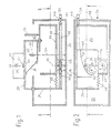
- FIG. 1 The schematic diagram according to Figures 1 and 2 of an imaginary Embodiment of a device for converting the Light signals from desired sections of a flat Object, e.g. a slide into video signals Housing 20, within which one as an article carrier serving object carriage 21 in the drawing plane and parallel to the bottom 22 of the housing 20, that is to say in the longitudinal direction of the housing is slidably mounted.
- An image carriage 23 is relatively displaceable slidably connected to the object carriage 21. Between the two carriages, there is a whole designated 24 Gear provided.
- a support 34 On the way of this Beam of light from the mirror 31 to the sensor surface 33 is arranged on a support 34, a lens 35, the one horizontal optical axis 30 defined by the mirror 31 is continued in a vertical deflection 30 '.
- the carrier 34 is fixedly connected to the housing 20.
- That connecting the object carriage 21 with the picture carriage 23 Transmission 24 has a cam bar 37, which in a Dovetail guide bar 38 of the article carriage 21 can be moved parallel to the plane of the drawing in Fig Item car 21 is connected.
- a Knurled screw 36 is provided to move the Curve strip 37 relative to the object carriage 21 and thus to focus the optical device.
- the curve bar 37 is provided with a curve 41 on which a sensing roller 42 abuts, which is rotatable on a lever 43 is mounted, which is arranged around a fixed on the housing base 22 Axis 44 is pivotable and at its extreme end carries a second sensing roller 45, which is also rotatable on Lever 43 is mounted.
- the second sensing roller 45 bears against a lower projection 46 of the image carriage 23.
- This is connected to the object carriage 21 by means of a tension spring 47, by means of which the projection 46 is pressed against the second sensing roller 45 and the curve 41 in the opposite direction against the first sensing roller 42.
- the gear 24 determines the relative position of the object carriage 21 to the image carriage 23. If the object carriage 21 is moved horizontally to the left in the plane of the drawing in FIG. 1, then the feeler roller 42 follows the curve 41 and pivots the lever 43 in a clockwise direction, so that by the force of the spring 47 of the image carriage 23 follows this pivoting movement of the lever. This movement of the object carriage 21, which is directed to the left in the illustration in FIGS.
- a recess 49 is provided for the screw 36 in the right end wall 48 of the housing 20, from which the screw 36 comes out completely when the object carriage 21 is in its extreme right in FIGS. 1 and 2 Position in which the object distance g min has the smallest value.
- the largest enlargement of the image of the slide is shown in the plane of the sensor surface 33.
- the image generated by the CCD sensor on a monitor can be focused by turning the screw 36. This focusing is particularly necessary because the device should be usable for both glazed and non-glazed slides.
- the object car is shown in the representation according to the 1 and 2 shifted to the right and thereby the object distance decreased until the whole cutout you want enlarged the full screen of the monitor fills.
- the lens 35 firmly connected to the housing 20.
- the object carriage 21 and the image carriage 23 is always adjustable relative to one another, that the desired section of the slide is sharp on the Sensor surface 33 is mapped.
- the basis of the invention a lying idea can also be realized by that the object, e.g. the slide, and / or the sensor surface 33 are fixedly arranged relative to the housing 20 and others Elements adjustable along the optical axis according to the known mathematical relationship through a gearbox with each other are connected.
- FIGS. 3 and 4 Two examples of such embodiments are shown in FIGS. 3 and 4. These are to clarify the functional principle, drawn very schematically simplified Representations in which details that are in the craft Can be the expert, for the sake of clarity are omitted.
- the parts that correspond to those of the in Fig. 1 and 2 illustrated embodiment in their function are the same, but with a and b respectively Reference numerals so that by this reference about the reference numbers in the description of the following Embodiments to the description of the first described Embodiment is referred to unnecessary Avoid repetitions.
- the object carriage 21a is in longitudinally movable in the same way relative to the housing 20a the object carriage 21 of the first described example. How in the examples described above, one is also the Device enabling rotation of the article carrier (Turntable) available.
- the roof mirror 205 is at the end of a two-armed pivot lever 207 firmly attached to the housing 20a at 209 is pivotally mounted and on its roof mirror 205 opposite end portion a rotatable sensing roller 42a bears by the force of gravity of much longer trained, the lever arm 205 carrying other lever arm pressed on the guide curve 41a of the curve strip 37a is.
- the feeler roller 42a runs on the guide curve 41a results in the aforementioned position adjustment of the roof mirror 205 in the direction of the double arrow 203, whereby a corresponding change in the image width is effected.
- the position is adjusted of the roof mirror 205 is not rectilinear along the optical axis 30a but slightly curved. Since both interacting reflective surfaces 211 and 212 of the Roof mirror 205 form a right angle with one another, leads the slight pivoting movement of the roof mirror 205 did not change the angular position of the optical axis 30a but only a minor one lateral radiation displacement, i.e. to a position displacement of the detail of the object imaged on the sensor 32a. If necessary, this can be done by changing the detail effecting adjustment of the object carriage 21a can be compensated.
- the fundamental difference is in Fig. 3 for the first described example in that the CCD sensor 32a is firmly connected to the housing 20a.
- the fixed arrangement is particularly favorable if the sensor 32a has additional devices are optically upstream.
- it is a rotatable color filter disc 213, which is rotatable by means of a servomotor 215 is to successively desired color filter areas of the color filter disk 213 to align with the optical axis 30a. This can be done in a known manner when using a black and white sensitive sensor 32a a color video signal produce.
- the wheel 217 is concentric with its axis of rotation cut-outs on plane-parallel optical plates, each of which a desired plane-parallel plate on the optical axis 30a can be aligned.
- the plane parallel Plates have different relative to the optical axis 30a Inclinations on.
- the wheel 217 forms with the plane-parallel plates a controllable optical beam shifter.
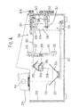
- FIG. 4 looks just like the example Fig. 3, a fixed arrangement of the CCD sensor 32b relative to Housing 20b in front.
- the sensor 32b are also the same Auxiliary devices as described above, optically upstream, namely with a color filter wheel 313 an actuator 315 and a wheel 317, which act as a jet displacer serves and carries plane-parallel optical disks, whereby the wheel 317 can be rotated step by step by means of a servomotor 319 is.
- a roof mirror 305 as adjustable by means of the gear 24b along the optical axis 30b Element available.
- the roof mirror 305 is located arm yourself at the end of one around a camp 309 swiveling pivot lever 307, which has a through Weight influence of the lever 307 on a guide curve 41b of a guide bar 37b guided roller 42b adjustable in position is so that the roof mirror 305 for changing the image width by means of the feeler roller 42b and the guide curve 41b formed gear 24b is adjustable.
- the movement takes place the curve bar 37b not by longitudinally moving the Object car 21b, but this is with the curve bar 37b not coupled.
- the object carriage 21b forms in this embodiment, therefore, no along the optical Axis 30b adjustable element for changing the Object distance. Rather, this is a second Roof mirror 331 in place, the two a right angle including reflective surfaces 333 and 334 and at the end portion of a second pivot lever 337 is firmly attached.
- the movement of the second roof mirror 331 for setting the object width by changing the pivot position of the pivot lever 337 around its pivot bearing 339 using a threaded spindle 341, which is articulated on the curve bar 37b, which in turn is firmly connected to the lever 337.
- the threaded spindle 341 is threadedly engaged with an adjusting nut 343 which is rotatable by means of a hand button 345.
- the feeler roller 42b runs on the guide curve 41b , whereby the roof mirror 305 one for moving the second Roof mirror 331 performs related movement so that the mapping equation is satisfied.
- the feeler roller 42b with the pivot lever 307th not firmly connected, but mounted on a bearing block 351, the along the lever 307 with the help of an adjusting screw 36b is adjustable, the function of the Screw 36 of FIGS. 1 and 2 corresponds.
Description
Die Erfindung betrifft eine Vorrichtung zum Umwandeln der Lichtsignale eines an einem Gegenstandsträger befindlichen flachen Gegenstandes, der sich im wesentlichen in einer Dingebene erstreckt, z.B. eines Diapositives oder eines Dia-negatives, in Videosignale.The invention relates to a device for converting the Light signals from one located on an article carrier flat object, which is essentially in a Thing plane extends, e.g. a slide or a slide negative, in video signals.
Vorrichtungen dieser Art mit einem Gehäuse, einem ersten
Träger für den Gegenstand, einem zweiten Träger für einen
CCD-Sensor, der den gewünschten Ausschnitt punktweise abtastet
und in Videosignale umwandelt, und einer ein Objektiv
aufweisenden optischen Einrichtung, die zur Abbildung des
gewünschten Ausschnittes auf dem CCD-Sensor einstellbar ist
und eine optische Achse definiert, sind z.B. bekannt durch
den Kodak SV 500 Videotransfer Stand (Zeitschrift
foto-contact 11/87, Seite 19) und den Fotovix film/video-processor
der Firma Tamron, der im Aufsatz "Slides on the
move" in der Zeitschrift Industrial Photography, Februar
1988, Seite 31, beschrieben ist. Bei diesen bekannten.
Vorrichtungen wird als Objektiv ein Zoom-Objektiv benutzt,
um zur Abbildung von verschieden großen Ausschnitten des
Gegenstandes diesen verschieden vergrößern zu können.Devices of this type with a housing, a first
Carrier for the object, a second carrier for one
CCD sensor that scans the desired section point by point
and converted into video signals, and one a lens
having optical device used to image the
desired section on the CCD sensor is adjustable
and an optical axis are defined, e.g. known by
the Kodak SV 500 video transfer stand (magazine
foto-contact 11/87, page 19) and the Fotovix film / video processor
from the company Tamron, which in the article "Slides on the
move "in the magazine Industrial Photography, February
1988,
DE-36 30 739 offenbart ein Verfahren und eine Vorrichtung, bei dem/der zur Datenaufnahme mittels Detektorarray eine gezielte Ortsveränderung zwischen Objekt und Array statffindet, wodurch eine höhere Auflösung von Objekten erfolgt, so daß sich Signalverbesserungen durch Mittelung, Farbkameras oder hochauflösende Strukturen realisieren lassen.DE-36 30 739 discloses a method and an apparatus in which a targeted change of location for data acquisition by means of a detector array between object and array, resulting in a higher resolution of Objects, so that signal improvements are achieved by averaging, Have color cameras or high-resolution structures implemented.
Der Erfindung liegt die Aufgabe zugrunde, eine Vorrichtung mit möglichst hoher Bildauflösung und geringem Kostenaufwand zu schaffen.The invention has for its object a device with the highest possible image resolution and low costs to accomplish.
Diese Aufgabe der Erfindung ist bei einer Vorrichtung der eingangs genannten Art durch die Merkmale des gekennzeichneten Teil des Anspruchs 1 gelöst.This object of the invention is in a device initially mentioned type by the features of the marked Part of claim 1 solved.
Eine längs der optischen Achse unverschiebbare Anordnung des CCD-Sensors ist hierbei besonders vorteilhaft, wenn im Strahlengang unmittelbar vor der Sensorfläche Zusatzeinrichtungen vorhanden sind, die dazu dienen, die auf die Sensorfläche treffenden Lichtstrahlen zu beeinflussen. Bei diesen Einrichtungen kann es sich um einen Strahlversetzer handeln, der es ermöglicht, eine gesteuerte Strahlversetzung längs der Ebene der Sensorfläche zu bewirken. Bei einem CCD-Sensor, bei dem die Lücken zwischen aneinander angrenzenden Pixeln Empfindlichkeitssenken darstellen, ergibt sich dadurch die Möglichkeit, beim Aufbau des die Bildinformation des Gegenstandes wiedergebenden Videosignals schrittweise so vorzugehen, daß Lichtstrahlen, die ein und derselben Bildinformation entsprechen, durch Strahlversetzung auf verschiedenen Stellen der Sensorfläche auftreffen, so daß auch diejenige Bildinformation zur Signalerzeugung verwendet werden kann, die ohne Strahlversetzung auf eine Lücke zwischen Pixeln auftreffen würde.An arrangement of the CCD sensor is particularly advantageous if in Beam path directly in front of the sensor surface are present, which are used on the sensor surface to affect striking light rays. With these Facilities can be a beam displacer, which enables a controlled beam displacement along the level of the sensor surface. With a CCD sensor, where the gaps between adjacent This results in pixels representing sensitivity sinks the possibility of building the image information of the object reproducing video signal gradually so proceed that light rays, the same image information correspond by beam displacement on different Make contact with the sensor surface so that too that image information is used for signal generation can without a beam shift to a gap between Pixels would hit.
Als Strahlversetzer können planparallele optische Platten vorgesehen sein, die unterschiedliche Neigungen relativ zur optischen Achse besitzen und wahlweise in den Strahlengang einführbar sind. Die planparallelen Platten können an einem Halter in Form eines Rades angebracht sein, wobei die planparallelen Platten in konzentrisch zur Drehachse des Rades gelegenen Ausschnitten gehalten sind. Durch Drehen des Rades mittels eines Stellantriebes können gewünschte planparallele Platten im Strahlengang zur Wirkung gebracht werden.Plane-parallel optical plates can be used as beam displacers be provided, the different inclinations relative to own optical axis and optionally in the beam path can be introduced. The plane-parallel plates can on one Holder in the form of a wheel attached, the plane-parallel Plates concentric to the axis of rotation of the wheel cutouts are held. By turning the wheel desired plane-parallel can be achieved by means of an actuator Plates can be brought into effect in the beam path.
Als dem CCD-Sensor im Strahlengang vorgeschaltete Zusatzeinrichtung kann auch ein Farbfilterrad vorhanden sein, das es in üblicher Weise ermöglicht, mittels eines schwarz-weiß empfindlichen CCD-Sensors Farb-Videosignale zu erzeugen, indem die Farbinformation des Gegenstandes schrittweise unter Einschalten verschiedener Farbfilter in den Strahlengang abgetastet wird.As an additional device upstream of the CCD sensor in the beam path there may also be a color filter wheel that it enabled in the usual way, by means of a black and white sensitive CCD sensor to generate color video signals by gradually adding the item's color information by switching on different color filters in the beam path is scanned.
Die Vorrichtung gemäß der Erfindung ist für jede Art von Gegenständen und insbesondere auch für nicht durchscheinende Bilder verwendbar, die mit der optischen Einrichtung auf einer Sensorfläche des CCD-Sensors abbildbar sind. The device according to the invention is for each type of Objects and especially for non-translucent ones Images usable with the optical device on a sensor surface of the CCD sensor can be mapped.
Die Erfindung ist in der folgenden Beschreibung von in den Zeichnungen schematisch vereinfacht dargestellten Ausführungsbeispielen im einzelnen erläutert.The invention is described in the following description of FIGS Drawings schematically illustrated embodiments explained in detail.
Es zeigen:
- Fig. 1
- einen vertikalen Längsschnitt nach der Linie I - I in Fig.2 eines das Prinzip der Erfindung darstellenden, nur gedachten ersten Ausführungsbeispiels;
- Fig. 2
- einen Schnitt nach der Linie II - II in Fig.1;
- Fig. 3 und 4
- schematisch stark vereinfacht und längs vertikaler Schnittebenen aufgeschnitten gezeichnete Seitenansichten von zwei weiteren Ausführungsbeispielen.
- Fig. 1
- a vertical longitudinal section along the line I - I in Figure 2 of a first embodiment representing the principle of the invention, only imagined;
- Fig. 2
- a section along the line II - II in Fig.1;
- 3 and 4
- schematically greatly simplified and cut along vertical section planes drawn side views of two further embodiments.
Die Prinzipdarstellung nach den Fig.1 und 2 eines gedachten
Ausführungsbeispiels einer Vorrichtung zum Umwandeln der
Lichtsignale von gewünschten Ausschnitten eines flachen
Gegenstandes, z.B. eines Dias, in Videosignale weist ein
Gehäuse 20 auf, innerhalb dessen ein als Gegenstandsträger
dienender Gegenstandswagen 21 in der Zeichenebene und
parallel zum Boden 22 des Gehäuses 20, also in Längsrichtung
des Gehäuses, verschiebbar gelagert ist. In der gleichen
Verschieberichtung verschiebbar ist ein Bildwagen 23 relativ
zum Gegenstandswagen 21 verschiebbar mit diesem verbunden.
Zwischen beiden Wagen ist ein als Ganzes mit 24 bezeichnetes
Getriebe vorgesehen.The schematic diagram according to Figures 1 and 2 of an imaginary
Embodiment of a device for converting the
Light signals from desired sections of a flat
Object, e.g. a slide into
Auf dem Gegenstandswagen 21 ist eine bauliche Einheit 25
angeordnet.There is a
Diese ist auf dem Gegenstandswagen in zwei zueinander senkrechten
waagerechten Richtungen verschiebbar und um eine
vertikale, zum Boden 22 senkrechte Achse drehbar, mit dem
Gegenstandswagen 21 verbunden. In der baulichen Einheit 25
befindet sich eine Lampe 26 und ein Halter 27 für ein den
abzubildenden Gegenstand tragendes Diapositiv (im folgenden
kurz "Dia" genannt). In der oberen Wandung 28 des Gegenstandswagens
21 befindet sich eine Öffnung 29. Unter der
Öffnung 29 ist ein Spiegel 31 im Gegenstandswagen 21 fest
angeordnet, dessen zur Zeichenebene senkrechte Spiegelebene
unter einem Winkel von 45o gegenüber der Vertikalen geneigt
ist. Auf dem Bildwagen 23 ist ein CCD-Sensor 32 so angeordnet,
daß das Licht der Lampe 26, nachdem es das im Halter 27
angeordnete Dia passiert und vom Spiegel 31 reflektiert worden
ist, auf die Sensorfläche 33 fällt. Auf dem Wege dieses
Lichtstrahlenbündels vom Spiegel 31 zur Sensorfläche 33 ist
auf einem Träger 34 ein Objektiv 35 angeordnet, das eine
waagerechte optische Achse 30 definiert, die durch den Spiegel
31 in einer vertikalen Umlenkung 30' fortgesetzt ist.
Der Träger 34 ist fest mit dem Gehäuse 20 verbunden.This is on the object carriage in two mutually perpendicular
horizontally displaceable and by one
vertical axis perpendicular to the
Das den Gegenstandswagen 21 mit dem Bildwagen 23 verbindende
Getriebe 24 weist eine Kurvenleiste 37 auf, die in einer
Schwalbenschwanz-Führungsleiste 38 des Gegenstandswagens 21
parallel zur Zeichenebene in Fig.2 verschiebbar mit dem
Gegenstandswagen 21 verbunden ist. Zum Verschieben der
Kurvenleiste 37 relativ zum Gegenstandswagen 21 und damit
zum Scharfeinstellen der optischen Einrichtung ist eine
Rändelschraube 36 vorgesehen.That connecting the
Die Kurvenleiste 37 ist mit einer Kurve 41 versehen, an der
eine Tastrolle 42 anliegt, die an einem Hebel 43 drehbar
gelagert ist, der um eine am Gehäuseboden 22 fest angeordnete
Achse 44 schwenkbar ist und an seinem äußersten Ende
eine zweite Tastrolle 45 trägt, die ebenfalls drehbar am
Hebel 43 gelagert ist.The
Die zweite Tastrolle 45 liegt an einem unteren Vorsprung 46
des Bildwagens 23 an. Dieser ist mit dem Gegenstandswagen 21
mittels einer Zugfeder 47 verbunden, durch die der Vorsprung
46 an die zweite Tastrolle 45 und die Kurve 41 in entgegengesetzter
Richtung an die erste Tastrolle 42 gedrückt werden.
Dadurch bestimmt das Getriebe 24 die relative Stellung
des Gegenstandswagens 21 zum Bildwagen 23. Wird nämlich der
Gegenstandswagen 21 horizontal in der Zeichenebene der Fig.1
nach links bewegt, dann folgt die Tastrolle 42 der Kurve 41
und schwenkt den Hebel 43 im Uhrzeigersinn, so daß durch die
Kraft der Feder 47 der Bildwagen 23 dieser Schwenkbewegung
des Hebels folgt. Durch diese aus der Darstellung in den
Fig.1 und 2 nach links gerichtete Bewegung des Gegenstandswagens
21 wird die Gegenstandsweite oder der Gegenstandsabstand
g des im Halter 27 gehaltenen Dias von der entsprechenden
Hauptebene des Objektivs 35 vergrößert und gleichzeitig
die Bildweite oder der Bildabstand b der Sensorfläche
33 von der entsprechenden Hauptebene des Objektivs 35 verringert.
Die Kurve 41 ist dabei so ausgelegt, daß z.B. bei
einer auf beiden Seiten gleichen Brennweite f des Objektivs
35 das Abbildungsgesetz
Wie aus Fig.2 ersichtlich ist, ist für die Schraube 36 in
der rechten Endwand 48 des Gehäuses 20 eine Aussparung 49
vorgesehen, aus der die Schraube 36 ganz heraustritt, wenn
sich der Gegenstandswagen 21 in seiner in den Fig.1 und 2
äußerst rechten Stellung befindet, in der der Gegenstandsabstand
gmin den kleinsten Wert hat. In dieser Stellung wird
die größte Vergrößerung des Bildes des Dias in der Ebene der
Sensorfläche 33 abgebildet. In dieser Stellung kann durch
Drehen der Schraube 36 das vom CCD-Sensor auf einem Monitor
erzeugte Bild scharf eingestellt werden. Diese Scharfeinstellung
ist insbesondere deswegen notwendig, weil die Vorrichtung
sowohl für verglaste als auch nicht verglaste Dias
verwendbar sein soll. As can be seen from FIG. 2, a
Durch die Schraube 36 kann die durch die Dicke des Glases
bedingte Änderung des Gegenstandsabstandes berücksichtigt
werden.By the
Aus der oben angegebenen Abbildungsgleichung ergibt sich die
Abhängigkeit des Bildabstandes vom Gegenstandsabstand für
den Fall, daß die Brennweite f als Längeneinheit gewählt
wird, zu
Der Vergrößerungsfaktor der oben beschriebenen optischen
Einrichtung ergibt sich zu
Die Sensorflächenhöhe beträgt 1/6 von der Diahöhe. Nimmt man die Brennweite des Objektivs f = 1 als Längeneinheit, dann wird ein Dia auf der ganzen Sensorfläche bei einem Gegenstandsabstand g = 7 abgebildet, denn es ergibt sich dann ein Bildabstand von b = 7/6, demnach ein Vergrößerungsfaktor β = 1/6.The sensor surface height is 1/6 of the slide height. Taking the focal length of the lens f = 1 as a unit of length, then becomes a slide on the entire sensor surface at an object distance g = 7, because it then results in a Image distance of b = 7/6, therefore a magnification factor β = 1/6.
Auf dem vom Sensor gesteuerten Monitor erscheint dann das volle Diabild. Diese Darstellung wird im folgenden als Vergrößerung 1:1 mit einem Vergrößerungsfaktor Gamma = 6 x β bezeichnet.This then appears on the monitor controlled by the sensor full slide picture. This representation is called the enlargement below 1: 1 with a magnification factor of gamma = 6 x β designated.
Die folgende Tabelle gibt den Bildabstand b und die Vergrößerung
Gamma in Abhängigkeit vom Gegenstandsabstand g bei
f = 1 an:
Die Betriebsweise der oben beschriebenen gedachten Ausführungsform
ist denkbar einfach. Nachdem die Scharfeinstellung
mit dem kleinsten Gegenstandsabstand gmin eingestellt
worden ist, wird der Gegenstandswagen 21 nach links
bewegt, bis zu der Vergrößerung Gamma = 1. Jetzt wird die
bauliche Einheit 25 so verschoben und gedreht, daß sich der
gewünschte Ausschnitt in der Mitte des Bildschirmes des
Monitors befindet.The operation of the imaginary embodiment described above is very simple. After the focus has been set with the smallest object distance g min , the
Dann wird der Gegenstandswagen in der Darstellung nach den Fig. 1 und 2 nach rechts verschoben und dadurch der Gegenstandsabstand verringert, bis der ganze gewünschte Ausschnitt vergrößert den ganzen Bildschirm des Monitors ausfüllt.Then the object car is shown in the representation according to the 1 and 2 shifted to the right and thereby the object distance decreased until the whole cutout you want enlarged the full screen of the monitor fills.
Bei dem dargestellten Ausführungsbeispiel ist das Objektiv
35 mit dem Gehäuse 20 fest verbunden. Zum Einstellen der
verschiedenen Vergrößerungen sind der Gegenstandswagen 21
und der Bildwagen 23 relativ zueinander immer so verstellbar,
daß der gewünschte Ausschnitt des Dias scharf auf der
Sensorfläche 33 abgebildet wird. Die der Erfindung zu Grunde
liegende Idee kann jedoch auch dadurch verwirklicht werden,
daß der Gegenstand, z.B. das Dia, und/oder die Sensorfläche
33 gegenüber dem Gehäuse 20 fest angeordnet sind und andere
längs der optischen Achse einstellbare Elemente nach der bekannten
mathematischen Beziehung durch ein Getriebe miteinander
verbunden sind. In the illustrated embodiment, the
Zwei Beispiele derartiger Ausführungsformen sind in den Fig. 3 und 4 gezeigt. Diese sind zur Verdeutlichung des Funktionsprinzips, stark schematisch vereinfacht gezeichnete Darstellungen, in denen Einzelheiten, die im handwerklichen Können des Fachmanns liegen, der Übersichtlichkeit wegen weggelassen sind. Diejenigen Teile, die solchen des in Fig. 1 und 2 dargestellten Ausführungsbeispiels in ihrer Funktion entsprechen, sind mit den gleichen, jedoch mit a bzw. b versehenen Bezugszahlen bezeichnet, so daß durch diesen Hinweis über die Bezugszahlen bei der Beschreibung der folgenden Ausführungsbeispiele auf die Beschreibung des erstbeschriebenen Ausführungsbeispiels Bezug genommen wird, um unnötige Wiederholungen zu vermeiden.Two examples of such embodiments are shown in FIGS. 3 and 4. These are to clarify the functional principle, drawn very schematically simplified Representations in which details that are in the craft Can be the expert, for the sake of clarity are omitted. The parts that correspond to those of the in Fig. 1 and 2 illustrated embodiment in their function are the same, but with a and b respectively Reference numerals so that by this reference about the reference numbers in the description of the following Embodiments to the description of the first described Embodiment is referred to unnecessary Avoid repetitions.
Bei dem Beispiel nach Fig. 3 ist der Gegenstandswagen 21a in
gleicher Weise relativ zum Gehäuse 20a längsbeweglich wie
der Gegenstandswagen 21 des erstbeschriebenen Beispiels. Wie
bei den zuvor beschriebenen Beispielen ist auch eine die
Drehung des Gegenstandsträgers ermöglichende Einrichtung
(Drehscheibe) vorhanden.In the example according to FIG. 3, the
Bei der in Längsrichtung erfolgenden Verschiebung des Gegenstandswagens
21a erfolgt die Mitnahme der Kurvenleiste 37a
in deren Führungsrichtung, die mit einem Doppelpfeil 201 angegeben
ist. Bei dieser Bewegung von Gegenstandswagen 21a
und Kurvenleiste 37a relativ zum Gehäuse 20a und relativ zu
dem fest angebrachten Objektiv 35a ergibt sich eine Änderung
der Gegenstandsweite. Die entsprechende Anpassung der Bildweite
mit Hilfe des Getriebes 24a erfolgt durch einen Dachspiegel
205, der im Strahlengang zwischen Objektiv 35a und
einem dem CCD-Sensor 32a vorgeschalteten festen Umlenkspiegel
204 angeordnet und mittels des Getriebes 24a in
Richtung eines Doppelpfeils 203 verstellbar ist. Der Dachspiegel
205 ist am Endbereich eines zweiarmigen Schwenkhebels
207 fest angebracht, der am Gehäuse 20a bei 209
schwenkbar gelagert ist und an seinem dem Dachspiegel 205
entgegengesetzten Endbereich eine drehbare Tastrolle 42a
trägt, die durch Gewichtskrafteinfluß des wesentlich länger
ausgebildeten, den Dachspiegel 205 tragenden anderen Hebelarms
an die Führungskurve 41a der Kurvenleiste 37a angedrückt
ist. Beim Ablaufen der Tastrolle 42a an der Führungskurve
41a ergibt sich die erwähnte Lageeinstellung des Dachspiegels
205 in Richtung des Doppelpfeils 203, wodurch eine
entsprechende Änderung der Bildweite bewirkt wird.When the object carriage is moved in the
Trotz der verhältnismäßig großen Länge des den Dachspiegel
205 tragenden Hebelarms des Hebels 207 erfolgt die Lageverstellung
des Dachspiegels 205 nicht geradlinig längs der
optischen Achse 30a sondern leicht bogenförmig. Da beide
zusammenwirkenden reflektierenden Flächen 211 und 212 des
Dachspiegels 205 miteinander einen rechten Winkel einschließen,
führt die geringfügige Schwenkbewegung des Dachspiegels
205 nicht zu einer Änderung der Winkellage der
optischen Achse 30a sondern lediglich zu einer geringfügigen
seitlichen Strahlenversetzung, also zu einer Lageversetzung
des auf dem Sensor 32a abgebildeten Ausschnittes des Gegenstandes.
Dies kann erforderlichenfalls durch eine die Ausschnittsveränderung
bewirkende Verstellung des Gegenstandswagens
21a kompensiert werden.Despite the relatively large length of the
Wie bei dem erstbeschriebenen Ausführungsbeispiel, wo
mittels der Schraube 36 eine relative Lageverstellung
zwischen Kurvenleiste 37 und Gegenstandswagen 21 zur Scharfeinstellung
vorhanden ist, sind auch bei dem Beispiel von
Fig. 3 nicht gezeigte Einstellmittel für diesen Zweck vorhanden.As in the first described embodiment, where
a relative position adjustment by means of the
Wie erwähnt, besteht bei Fig. 3 der grundlegende Unterschied
zum erstbeschriebenen Beispiel darin, daß der CCD-Sensor 32a
fest mit dem Gehäuse 20a verbunden ist. Die feste Anordnung
ist besonders günstig, wenn dem Sensor 32a Zusatzeinrichtungen
optisch vorgeschaltet sind. Beim gezeigten Beispiel
handelt es sich hierbei um eine drehbar gelagerte Farbfilterscheibe
213, die mittels eines Stellmotors 215 drehbar
ist, um nacheinander gewünschte Farbfilterbereiche der Farbfilterscheibe
213 auf die optische Achse 30a auszurichten.
In bekannter Weise läßt sich dadurch bei Verwendung eines
schwarz-weiß empfindlichen Sensors 32a ein Farb-Videosignal
erzeugen.As mentioned, the fundamental difference is in Fig. 3
for the first described example in that the
Als weitere Zusatzeinrichtung ist ein in ähnlicher Weise wie
die Farbfilterscheibe 213 drehbar gelagertes Rad 217 vorgesehen,
das durch einen Stellmotor 219 in Schritten drehbar
ist. Das Rad 217 weist in konzentrisch zu seiner Drehachse
gelegenen Ausschnitten planparallele optische Platten auf,
von denen je eine gewünschte planparallele Platte auf die
optische Achse 30a ausrichtbar ist. Die planparallelen
Platten weisen relativ zur optischen Achse 30a unterschiedliche
Neigungen auf. Dadurch bildet das Rad 217 mit den
planparallelen Platten einen steuerbaren optischen Strahlversetzer.
Mit dessen Hilfe ist es möglich, das Videosignal
in mehreren Schritten aufzubauen, wobei durch Wahl der Drehstellung
des Rades 217 bei jedem Schritt eine Strahlversetzung
in der Weise vorgenommen wird, daß Bildinformationen
die ohne Strahlversetzung in die unwirksamen Lücken zwischen
aneinandergrenzenden Pixeln des Sensors 32a fallen würden,
auf den empfindlichen Bereich der betreffenden Pixel auftreffen
und daher für die Bildsignalerzeugung nicht verlorengehen.As an additional device is a similar to
the
Das Beispiel nach Fig. 4 sieht, ebenso wie das Beispiel nach
Fig. 3, eine feste Anordnung des CCD-Sensors 32b relativ zum
Gehäuse 20b vor. Dem Sensor 32b sind auch die gleichen
Zustzeinrichtungen, wie sie zuvor beschrieben wurden,
optisch vorgeschaltet, nämlich ein Farbfilterrad 313 mit
einem Stellmotor 315 und ein Rad 317, das als Strahlversetzer
dient und planparallele optische Platten trägt, wobei
das Rad 317 durch einen Stellmotor 319 schrittweise drehbar
ist. The example of FIG. 4 looks just like the example
Fig. 3, a fixed arrangement of the CCD sensor 32b relative to
Wie bei dem Beispiel nach Fig. 3 ist im Strahlengang
zwischen Objektiv 35b und einem dem Sensor 32b vorgeschalteten
festen Umlenkspiegel 304 ein Dachspiegel 305 als
mittels des Getriebes 24b längs der optischen Achse 30b einstellbares
Element vorhanden. Der Dachspiegel 305 befindet
sich an dem Endbereich eines hier einarmigen, um ein Lager
309 schwenkbaren Schwenkhebels 307, der über eine durch
Gewichtskrafteinfluß des Hebels 307 an einer Führungskurve
41b einer Führungsleiste 37b geführte Tastrolle 42b lageverstellbar
ist, so daß der Dachspiegel 305 zur Bildweitenänderung
mittels des von der Tastrolle 42b und der Führungskurve
41b gebildeten Getriebes 24b einstellbar ist.As in the example of Fig. 3 is in the beam path
between lens 35b and one upstream of sensor 32b
fixed deflecting mirror 304 a
Im Unterschied zum Beispiel gemäß Fig. 3 erfolgt die Bewegung
der Kurvenleiste 37b nicht durch Längsverschieben des
Gegenstandswagens 21b, sondern dieser ist mit der Kurvenleiste
37b nicht gekoppelt. Der Gegenstandwagen 21b bildet
bei dieser Ausführungsform daher auch kein längs der optischen
Achse 30b einstellbares Element zur Änderung der
Gegenstandsweite. Zu diesem Zweck ist vielmehr ein zweiter
Dachspiegel 331 vorhanden, der zwei einen rechten Winkel
miteinander einschließende reflektierende Flächen 333 und
334 aufweist und am Endbereich eines zweiten Schwenkhebels
337 fest angebracht ist. Die Bewegung des zweiten Dachspiegels
331 zur Einstellung der Gegenstandweite erfolgt
durch Verändern der Schwenkstellung des Schwenkhebels 337 um
sein Schwenklager 339 mit Hilfe einer Gewindespindel 341,
die an der Kurvenleiste 37b angelenkt ist, welche ihrerseits
mit dem Hebel 337 fest verbunden ist. Die Gewindespindel 341
ist mit einer Stellmutter 343 in Gewindeeingriff, die
mittels eines Handknopfes 345 drehbar ist.In contrast to the example according to FIG. 3, the movement takes place
the
Bei der Schwenkbewegung der Kurvenleiste 37b um das Schwenklager
339 läuft die Tastrolle 42b an der Führungskurve 41b
ab, wodurch der Dachspiegel 305 eine zur Bewegung des zweiten
Dachspiegels 331 so in Bezug stehende Bewegung durchführt,
daß der Abbildungsgleichung genüge geleistet wird. Um
eine relative Lageverstellung zwischen Dachspiegel 305 und
zweitem Dachspiegel 331 zum Zwecke einer Scharfstellung zu
ermöglichen, ist die Tastrolle 42b mit dem Schwenkhebel 307
nicht fest verbunden, sondern an einem Lagerbock 351 gelagert,
der längs des Hebels 307 mit Hilfe einer Einstellschraube
36b verstellbar ist, die funktionsmäßig der
Schraube 36 von Fig. 1 und 2 entspricht.When the
Durch eine im handwerklichen Können des Fachmanns liegende Beleuchtung eines undurchsichtigen Bildes anstelle eines Dias kann das Bild in ähnlicher Weise auf dem CCD-Sensor abgebildet werden.By a skilled in the art Illumination of an opaque image instead of one The image can similarly slide on the CCD sensor be mapped.
Die vorstehende Beschreibung und die Zeichnung beschränken sich nur auf die Angabe von Merkmalen, die für die beispielsweise Verkörperung der Erfindung wesentlich sind.Limit the foregoing description and drawings focus only on the specification of characteristics for the for example embodiment of the invention are essential.
Claims (4)
- Device for converting into video signals the light signals of a flat object which is provided on an object carrier (21; 21a; 21b) and extends substantially in an object plane, by means of a CCD sensor (32; 32a; 32b) arranged on a carrier and by means of an optical system comprising a lens unit (35; 35a; 35b), said unit defining a raypath with an optical axis (30; 30a; 30b) and being adjustable for imaging the object on the CCD sensor (32; 32a; 32b), characterized in that the optical system comprises controllable beam displacement means (217, 219; 317, 319) which, via an actuator (219; 319), cause the light beams impinging upon the CCD sensor (32a; 32b) to be optionally displaced in plane-parallel fashion along the plane of its sensor surface so that image information which would drop into ineffective gaps between adjacent sensitive sensor surfaces of said CCD sensor impinge upon sensitive surfaces of said sensor.
- Device according to claim 1, characterized in that the beam displacement means (217; 317) comprise at least one plane-parallel optical plate which is arranged at an inclination with respect to the direction of the raypath.
- Device according to claim 2, characterized in that the displacement means (217; 317) comprise a plurality of plane-parallel plates which are inclined relative to the raypath at different angles and/or in different directions, one of said plates being optionally selectible by movement of said beam displacement means via the actuator (219; 319).
- Device according to claim 3, characterized in that the beam displacement means (217, 317) are configured as a wheel which carries the plane-parallel plates in sections concentric relative to its axis of rotation and which is rotatable into desired rotary positions by means of the actuator (219, 319).
Applications Claiming Priority (3)
| Application Number | Priority Date | Filing Date | Title |
|---|---|---|---|
| DE3922512A DE3922512A1 (en) | 1989-07-08 | 1989-07-08 | DEVICE FOR CONVERTING LIGHT SIGNALS TO VIDEO SIGNALS |
| DE3922512 | 1989-07-08 | ||
| EP90910706A EP0482047B1 (en) | 1989-07-08 | 1990-07-06 | Device for converting light signals to video signals |
Related Parent Applications (2)
| Application Number | Title | Priority Date | Filing Date |
|---|---|---|---|
| EP90910706A Division EP0482047B1 (en) | 1989-07-08 | 1990-07-06 | Device for converting light signals to video signals |
| EP90910706.2 Division | 1990-07-06 |
Publications (3)
| Publication Number | Publication Date |
|---|---|
| EP0635968A2 EP0635968A2 (en) | 1995-01-25 |
| EP0635968A3 EP0635968A3 (en) | 1995-02-15 |
| EP0635968B1 true EP0635968B1 (en) | 1998-10-28 |
Family
ID=6384576
Family Applications (2)
| Application Number | Title | Priority Date | Filing Date |
|---|---|---|---|
| EP94116459A Expired - Lifetime EP0635968B1 (en) | 1989-07-08 | 1990-07-06 | Device for converting light signals to video signals |
| EP90910706A Expired - Lifetime EP0482047B1 (en) | 1989-07-08 | 1990-07-06 | Device for converting light signals to video signals |
Family Applications After (1)
| Application Number | Title | Priority Date | Filing Date |
|---|---|---|---|
| EP90910706A Expired - Lifetime EP0482047B1 (en) | 1989-07-08 | 1990-07-06 | Device for converting light signals to video signals |
Country Status (6)
| Country | Link |
|---|---|
| US (1) | US5276534A (en) |
| EP (2) | EP0635968B1 (en) |
| JP (1) | JPH04506892A (en) |
| KR (1) | KR920702149A (en) |
| DE (3) | DE3922512A1 (en) |
| WO (1) | WO1991001070A1 (en) |
Families Citing this family (9)
| Publication number | Priority date | Publication date | Assignee | Title |
|---|---|---|---|---|
| US5568273A (en) * | 1993-03-05 | 1996-10-22 | Canon Kabushiki Kaisha | Image reading apparatus with image magnification and scanning speed changed to correct for focus adjustment |
| US5467172A (en) * | 1994-06-15 | 1995-11-14 | Liao; Chun-Chi | Image scanner transparency adaptor |
| US5663762A (en) * | 1994-10-24 | 1997-09-02 | Fuji Photo Film Co., Ltd. | Electronic viewer automatically adjusting magnification of a film image in accordance with position of the film image |
| CA2153210A1 (en) * | 1995-06-30 | 1996-12-31 | C. Rex Welsh | Apparatus and method for computerized acquisition of x-ray images |
| DE19539690C2 (en) * | 1995-10-25 | 1998-09-10 | Agfa Gevaert Ag | Copier |
| JPH10285113A (en) * | 1997-04-07 | 1998-10-23 | Kokusai Denshin Denwa Co Ltd <Kdd> | Gain equalization device and optical amplification transmission line |
| US20020186475A1 (en) * | 2001-06-11 | 2002-12-12 | Yin-Chun Huang | Optical system for scanner |
| TW568477U (en) * | 2002-10-31 | 2003-12-21 | Lite On Technology Corp | Image detecting apparatus |
| US8970677B2 (en) * | 2008-02-19 | 2015-03-03 | Bae Systems Information And Electronic Systems Integration Inc. | Focus actuated vergence |
Family Cites Families (15)
| Publication number | Priority date | Publication date | Assignee | Title |
|---|---|---|---|---|
| US3728019A (en) * | 1971-09-13 | 1973-04-17 | Eastman Kodak Co | Auto-focus printing below 1,1 {33 {0 magnification |
| US4562485A (en) * | 1979-08-10 | 1985-12-31 | Canon Kabushiki Kaisha | Copying apparatus |
| JPS56153314A (en) * | 1980-04-15 | 1981-11-27 | Ricoh Co Ltd | Color information reader |
| JPS5972873A (en) * | 1982-10-19 | 1984-04-24 | Fuji Photo Film Co Ltd | Picture reproducer |
| JPS59162514A (en) * | 1983-03-08 | 1984-09-13 | Dainippon Screen Mfg Co Ltd | Focus adjusting method of image scanning and recording device |
| US4580172A (en) * | 1984-07-02 | 1986-04-01 | The Mead Corporation | Optical scanner for automatic document handler |
| JPS6157176A (en) * | 1984-08-29 | 1986-03-24 | Dainippon Screen Mfg Co Ltd | Magnification variable control method |
| US4707743A (en) * | 1985-02-19 | 1987-11-17 | Canon Kabushiki Kaisha | Method and apparatus for image conversion with multiple exposures for filtering |
| JPH06101780B2 (en) * | 1985-05-22 | 1994-12-12 | ミノルタ株式会社 | Image reader |
| US4812917A (en) * | 1986-03-20 | 1989-03-14 | Ricoh Company, Ltd. | Device for reducing document in size having two facing non-parallel mirrors |
| JPS6346065A (en) * | 1986-08-13 | 1988-02-26 | Fuji Photo Film Co Ltd | Image magnification changing method |
| DE3630739C1 (en) * | 1986-09-10 | 1988-04-07 | Zeiss Carl Fa | Method for data pick-up by means of detector arrays and devices for carrying out the methods |
| DK159088C (en) * | 1988-04-06 | 1991-01-28 | Oce Helioprint As | SCANNING TO DETECT AN ORIGINAL |
| US5012354A (en) * | 1988-04-27 | 1991-04-30 | Ricoh Company, Ltd. | Travelling carriage driving apparatus |
| US5140443A (en) * | 1989-07-25 | 1992-08-18 | Victor Company Of Japan, Ltd. | Image scanning apparatus |
-
1989
- 1989-07-08 DE DE3922512A patent/DE3922512A1/en not_active Withdrawn
-
1990
- 1990-07-06 KR KR1019910700258A patent/KR920702149A/en not_active Application Discontinuation
- 1990-07-06 DE DE59010854T patent/DE59010854D1/en not_active Expired - Fee Related
- 1990-07-06 EP EP94116459A patent/EP0635968B1/en not_active Expired - Lifetime
- 1990-07-06 WO PCT/EP1990/001097 patent/WO1991001070A1/en active IP Right Grant
- 1990-07-06 DE DE59009069T patent/DE59009069D1/en not_active Expired - Fee Related
- 1990-07-06 JP JP2510667A patent/JPH04506892A/en active Pending
- 1990-07-06 EP EP90910706A patent/EP0482047B1/en not_active Expired - Lifetime
-
1991
- 1991-03-07 US US07/659,336 patent/US5276534A/en not_active Expired - Fee Related
Also Published As
| Publication number | Publication date |
|---|---|
| DE3922512A1 (en) | 1991-01-17 |
| KR920702149A (en) | 1992-08-12 |
| DE59009069D1 (en) | 1995-06-14 |
| EP0482047B1 (en) | 1995-05-10 |
| JPH04506892A (en) | 1992-11-26 |
| EP0482047A1 (en) | 1992-04-29 |
| DE59010854D1 (en) | 1998-12-03 |
| EP0635968A3 (en) | 1995-02-15 |
| WO1991001070A1 (en) | 1991-01-24 |
| EP0635968A2 (en) | 1995-01-25 |
| US5276534A (en) | 1994-01-04 |
Similar Documents
| Publication | Publication Date | Title |
|---|---|---|
| DE3137031C2 (en) | Multiple beam scanning optics system | |
| EP1373981B1 (en) | Lithographic apparatus with a mobile lens for producing digital holograms | |
| DE2537411A1 (en) | DEVICE FOR SCANING THE CYLINDRICAL SURFACE OF A CYLINDER OR DGL. WITH A LASER BEAM, IN PARTICULAR TO MAINTAIN THE POSITION OF A WORKING HEAD IN RELATION TO A CYLINDRICAL WORKPIECE | |
| EP0635968B1 (en) | Device for converting light signals to video signals | |
| EP1377880B1 (en) | Lithograph and microscope with one-dimensional trigger mask and method for production of digital holograms in a storage medium | |
| DE1447450A1 (en) | Distance measuring or control device | |
| DE10116060B4 (en) | Lithograph with trigger mask and method for producing digital holograms in a storage medium | |
| EP0223957A1 (en) | Optoelectronic scanning head | |
| DE3310601A1 (en) | DISTANCE MEASURING DEVICE | |
| EP1538472B1 (en) | Image forming apparatus with movable microlens array for stabilized imaging of an object to a detector | |
| DE4219851A1 (en) | STEREOCAMERA | |
| DE102008019850A1 (en) | Apparatus and method for illuminating an object scene | |
| DE60105650T2 (en) | LIGHT-BREAKING OPTICAL REFLECTOR | |
| DE2924120A1 (en) | DEVICE FOR TWO-DIMENSIONAL SCANNING | |
| DE4127919C2 (en) | Light recording device | |
| DE3939856C2 (en) | ||
| DE10233491A1 (en) | Compact device for imaging a printing form | |
| WO2000002376A1 (en) | Scanning head for scanning documents | |
| DE3702691A1 (en) | Contactless ranging sensor | |
| DE3933065A1 (en) | LASER SCAN FOR PASSIVE FACET SCAN | |
| DE19752888C2 (en) | Micro-optical laser scanner and scanning method | |
| DE3047813A1 (en) | Photo sensitive printing process - uses modulated laser beam with signals directed via fibre optic elements onto material | |
| DE10210258A1 (en) | Multi-resolution scanner | |
| DE3208264C2 (en) | ||
| EP1322105A1 (en) | Device and method to capture a high resolution image in an image plane |
Legal Events
| Date | Code | Title | Description |
|---|---|---|---|
| PUAI | Public reference made under article 153(3) epc to a published international application that has entered the european phase |
Free format text: ORIGINAL CODE: 0009012 |
|
| PUAL | Search report despatched |
Free format text: ORIGINAL CODE: 0009013 |
|
| AC | Divisional application: reference to earlier application |
Ref document number: 482047 Country of ref document: EP |
|
| AK | Designated contracting states |
Kind code of ref document: A2 Designated state(s): DE FR GB |
|
| AK | Designated contracting states |
Kind code of ref document: A3 Designated state(s): DE FR GB |
|
| RIN1 | Information on inventor provided before grant (corrected) |
Inventor name: RENNER, MEINRAD Inventor name: MUTZE, ULRICH, DR. |
|
| 17P | Request for examination filed |
Effective date: 19950721 |
|
| 17Q | First examination report despatched |
Effective date: 19970701 |
|
| GRAG | Despatch of communication of intention to grant |
Free format text: ORIGINAL CODE: EPIDOS AGRA |
|
| GRAG | Despatch of communication of intention to grant |
Free format text: ORIGINAL CODE: EPIDOS AGRA |
|
| GRAH | Despatch of communication of intention to grant a patent |
Free format text: ORIGINAL CODE: EPIDOS IGRA |
|
| GRAH | Despatch of communication of intention to grant a patent |
Free format text: ORIGINAL CODE: EPIDOS IGRA |
|
| GRAA | (expected) grant |
Free format text: ORIGINAL CODE: 0009210 |
|
| AC | Divisional application: reference to earlier application |
Ref document number: 482047 Country of ref document: EP |
|
| AK | Designated contracting states |
Kind code of ref document: B1 Designated state(s): DE FR GB |
|
| RIN2 | Information on inventor provided after grant (corrected) |
Free format text: MUTZE, ULRICH, DR. * RENNER, MEINRAD |
|
| REF | Corresponds to: |
Ref document number: 59010854 Country of ref document: DE Date of ref document: 19981203 |
|
| ET | Fr: translation filed | ||
| GBT | Gb: translation of ep patent filed (gb section 77(6)(a)/1977) |
Effective date: 19990122 |
|
| PLBE | No opposition filed within time limit |
Free format text: ORIGINAL CODE: 0009261 |
|
| STAA | Information on the status of an ep patent application or granted ep patent |
Free format text: STATUS: NO OPPOSITION FILED WITHIN TIME LIMIT |
|
| 26N | No opposition filed | ||
| PGFP | Annual fee paid to national office [announced via postgrant information from national office to epo] |
Ref country code: GB Payment date: 20000614 Year of fee payment: 11 |
|
| PGFP | Annual fee paid to national office [announced via postgrant information from national office to epo] |
Ref country code: FR Payment date: 20000707 Year of fee payment: 11 |
|
| PGFP | Annual fee paid to national office [announced via postgrant information from national office to epo] |
Ref country code: DE Payment date: 20000727 Year of fee payment: 11 |
|
| PG25 | Lapsed in a contracting state [announced via postgrant information from national office to epo] |
Ref country code: GB Free format text: LAPSE BECAUSE OF NON-PAYMENT OF DUE FEES Effective date: 20010706 |
|
| GBPC | Gb: european patent ceased through non-payment of renewal fee |
Effective date: 20010706 |
|
| PG25 | Lapsed in a contracting state [announced via postgrant information from national office to epo] |
Ref country code: FR Free format text: LAPSE BECAUSE OF NON-PAYMENT OF DUE FEES Effective date: 20020329 |
|
| REG | Reference to a national code |
Ref country code: FR Ref legal event code: ST |
|
| PG25 | Lapsed in a contracting state [announced via postgrant information from national office to epo] |
Ref country code: DE Free format text: LAPSE BECAUSE OF NON-PAYMENT OF DUE FEES Effective date: 20020601 |