EP0635714A1 - Oil deterioration detection apparatus and apparatus for detecting particles in liquid - Google Patents
Oil deterioration detection apparatus and apparatus for detecting particles in liquid Download PDFInfo
- Publication number
- EP0635714A1 EP0635714A1 EP94110364A EP94110364A EP0635714A1 EP 0635714 A1 EP0635714 A1 EP 0635714A1 EP 94110364 A EP94110364 A EP 94110364A EP 94110364 A EP94110364 A EP 94110364A EP 0635714 A1 EP0635714 A1 EP 0635714A1
- Authority
- EP
- European Patent Office
- Prior art keywords
- light
- oil
- photosensor
- liquid
- examination
- Prior art date
- Legal status (The legal status is an assumption and is not a legal conclusion. Google has not performed a legal analysis and makes no representation as to the accuracy of the status listed.)
- Granted
Links
- 239000007788 liquid Substances 0.000 title claims abstract description 106
- 239000002245 particle Substances 0.000 title claims abstract description 87
- 230000006866 deterioration Effects 0.000 title claims abstract description 58
- 238000001514 detection method Methods 0.000 title description 122
- OKTJSMMVPCPJKN-UHFFFAOYSA-N Carbon Chemical compound [C] OKTJSMMVPCPJKN-UHFFFAOYSA-N 0.000 claims abstract description 18
- 229910052799 carbon Inorganic materials 0.000 claims abstract description 18
- 238000004140 cleaning Methods 0.000 claims description 39
- 230000003287 optical effect Effects 0.000 claims description 33
- 230000008859 change Effects 0.000 claims description 26
- 230000002265 prevention Effects 0.000 claims description 5
- 239000010687 lubricating oil Substances 0.000 abstract description 13
- 239000003921 oil Substances 0.000 description 138
- 230000001050 lubricating effect Effects 0.000 description 18
- 239000000693 micelle Substances 0.000 description 16
- 238000005259 measurement Methods 0.000 description 14
- 238000000034 method Methods 0.000 description 14
- 238000000151 deposition Methods 0.000 description 11
- 238000002834 transmittance Methods 0.000 description 11
- OFBQJSOFQDEBGM-UHFFFAOYSA-N Pentane Chemical compound CCCCC OFBQJSOFQDEBGM-UHFFFAOYSA-N 0.000 description 10
- 230000008021 deposition Effects 0.000 description 10
- -1 polytetrafluoroethylene Polymers 0.000 description 10
- 230000007423 decrease Effects 0.000 description 9
- 239000000463 material Substances 0.000 description 9
- 239000002689 soil Substances 0.000 description 8
- 238000010276 construction Methods 0.000 description 7
- 239000002270 dispersing agent Substances 0.000 description 6
- 230000000694 effects Effects 0.000 description 6
- 230000001965 increasing effect Effects 0.000 description 6
- 239000010705 motor oil Substances 0.000 description 6
- 238000002485 combustion reaction Methods 0.000 description 5
- 230000035945 sensitivity Effects 0.000 description 5
- 238000004519 manufacturing process Methods 0.000 description 4
- 239000000843 powder Substances 0.000 description 4
- 239000002253 acid Substances 0.000 description 3
- 230000005540 biological transmission Effects 0.000 description 3
- 230000003247 decreasing effect Effects 0.000 description 3
- 229920001973 fluoroelastomer Polymers 0.000 description 3
- 239000002184 metal Substances 0.000 description 3
- 229910052751 metal Inorganic materials 0.000 description 3
- 238000005070 sampling Methods 0.000 description 3
- 241000511976 Hoya Species 0.000 description 2
- XEEYBQQBJWHFJM-UHFFFAOYSA-N Iron Chemical group [Fe] XEEYBQQBJWHFJM-UHFFFAOYSA-N 0.000 description 2
- 238000011481 absorbance measurement Methods 0.000 description 2
- 238000010521 absorption reaction Methods 0.000 description 2
- 239000000654 additive Substances 0.000 description 2
- 230000002411 adverse Effects 0.000 description 2
- 230000002238 attenuated effect Effects 0.000 description 2
- 239000002199 base oil Substances 0.000 description 2
- 230000002708 enhancing effect Effects 0.000 description 2
- 229920002313 fluoropolymer Polymers 0.000 description 2
- 239000000446 fuel Substances 0.000 description 2
- 239000011521 glass Substances 0.000 description 2
- 230000005484 gravity Effects 0.000 description 2
- 238000005461 lubrication Methods 0.000 description 2
- 238000000691 measurement method Methods 0.000 description 2
- 230000003647 oxidation Effects 0.000 description 2
- 238000007254 oxidation reaction Methods 0.000 description 2
- 229920001343 polytetrafluoroethylene Polymers 0.000 description 2
- 239000004810 polytetrafluoroethylene Substances 0.000 description 2
- 238000012545 processing Methods 0.000 description 2
- 230000004044 response Effects 0.000 description 2
- 239000004576 sand Substances 0.000 description 2
- 239000007787 solid Substances 0.000 description 2
- 239000000126 substance Substances 0.000 description 2
- NCGICGYLBXGBGN-UHFFFAOYSA-N 3-morpholin-4-yl-1-oxa-3-azonia-2-azanidacyclopent-3-en-5-imine;hydrochloride Chemical compound Cl.[N-]1OC(=N)C=[N+]1N1CCOCC1 NCGICGYLBXGBGN-UHFFFAOYSA-N 0.000 description 1
- 230000015572 biosynthetic process Effects 0.000 description 1
- 239000000919 ceramic Substances 0.000 description 1
- 239000003795 chemical substances by application Substances 0.000 description 1
- 230000000052 comparative effect Effects 0.000 description 1
- 238000011161 development Methods 0.000 description 1
- 238000010586 diagram Methods 0.000 description 1
- 230000005684 electric field Effects 0.000 description 1
- 238000002847 impedance measurement Methods 0.000 description 1
- 238000009434 installation Methods 0.000 description 1
- 230000007246 mechanism Effects 0.000 description 1
- 238000012986 modification Methods 0.000 description 1
- 230000004048 modification Effects 0.000 description 1
- 230000008569 process Effects 0.000 description 1
- 230000009467 reduction Effects 0.000 description 1
- 239000011347 resin Substances 0.000 description 1
- 229920005989 resin Polymers 0.000 description 1
- 238000007789 sealing Methods 0.000 description 1
- 239000004065 semiconductor Substances 0.000 description 1
Images



Classifications
-
- G—PHYSICS
- G01—MEASURING; TESTING
- G01N—INVESTIGATING OR ANALYSING MATERIALS BY DETERMINING THEIR CHEMICAL OR PHYSICAL PROPERTIES
- G01N21/00—Investigating or analysing materials by the use of optical means, i.e. using sub-millimetre waves, infrared, visible or ultraviolet light
- G01N21/01—Arrangements or apparatus for facilitating the optical investigation
- G01N21/15—Preventing contamination of the components of the optical system or obstruction of the light path
-
- F—MECHANICAL ENGINEERING; LIGHTING; HEATING; WEAPONS; BLASTING
- F01—MACHINES OR ENGINES IN GENERAL; ENGINE PLANTS IN GENERAL; STEAM ENGINES
- F01M—LUBRICATING OF MACHINES OR ENGINES IN GENERAL; LUBRICATING INTERNAL COMBUSTION ENGINES; CRANKCASE VENTILATING
- F01M11/00—Component parts, details or accessories, not provided for in, or of interest apart from, groups F01M1/00 - F01M9/00
- F01M11/10—Indicating devices; Other safety devices
-
- G—PHYSICS
- G01—MEASURING; TESTING
- G01N—INVESTIGATING OR ANALYSING MATERIALS BY DETERMINING THEIR CHEMICAL OR PHYSICAL PROPERTIES
- G01N21/00—Investigating or analysing materials by the use of optical means, i.e. using sub-millimetre waves, infrared, visible or ultraviolet light
- G01N21/17—Systems in which incident light is modified in accordance with the properties of the material investigated
- G01N21/41—Refractivity; Phase-affecting properties, e.g. optical path length
- G01N21/43—Refractivity; Phase-affecting properties, e.g. optical path length by measuring critical angle
-
- G—PHYSICS
- G01—MEASURING; TESTING
- G01N—INVESTIGATING OR ANALYSING MATERIALS BY DETERMINING THEIR CHEMICAL OR PHYSICAL PROPERTIES
- G01N33/00—Investigating or analysing materials by specific methods not covered by groups G01N1/00 - G01N31/00
- G01N33/26—Oils; Viscous liquids; Paints; Inks
- G01N33/28—Oils, i.e. hydrocarbon liquids
- G01N33/2888—Lubricating oil characteristics, e.g. deterioration
-
- F—MECHANICAL ENGINEERING; LIGHTING; HEATING; WEAPONS; BLASTING
- F02—COMBUSTION ENGINES; HOT-GAS OR COMBUSTION-PRODUCT ENGINE PLANTS
- F02B—INTERNAL-COMBUSTION PISTON ENGINES; COMBUSTION ENGINES IN GENERAL
- F02B1/00—Engines characterised by fuel-air mixture compression
- F02B1/02—Engines characterised by fuel-air mixture compression with positive ignition
- F02B1/04—Engines characterised by fuel-air mixture compression with positive ignition with fuel-air mixture admission into cylinder
-
- F—MECHANICAL ENGINEERING; LIGHTING; HEATING; WEAPONS; BLASTING
- F16—ENGINEERING ELEMENTS AND UNITS; GENERAL MEASURES FOR PRODUCING AND MAINTAINING EFFECTIVE FUNCTIONING OF MACHINES OR INSTALLATIONS; THERMAL INSULATION IN GENERAL
- F16N—LUBRICATING
- F16N2200/00—Condition of lubricant
- F16N2200/02—Oxidation
-
- F—MECHANICAL ENGINEERING; LIGHTING; HEATING; WEAPONS; BLASTING
- F16—ENGINEERING ELEMENTS AND UNITS; GENERAL MEASURES FOR PRODUCING AND MAINTAINING EFFECTIVE FUNCTIONING OF MACHINES OR INSTALLATIONS; THERMAL INSULATION IN GENERAL
- F16N—LUBRICATING
- F16N2250/00—Measuring
- F16N2250/34—Transparency; Light; Photo sensor
-
- G—PHYSICS
- G01—MEASURING; TESTING
- G01N—INVESTIGATING OR ANALYSING MATERIALS BY DETERMINING THEIR CHEMICAL OR PHYSICAL PROPERTIES
- G01N21/00—Investigating or analysing materials by the use of optical means, i.e. using sub-millimetre waves, infrared, visible or ultraviolet light
- G01N21/01—Arrangements or apparatus for facilitating the optical investigation
- G01N21/15—Preventing contamination of the components of the optical system or obstruction of the light path
- G01N2021/152—Scraping; Brushing; Moving band
-
- G—PHYSICS
- G01—MEASURING; TESTING
- G01N—INVESTIGATING OR ANALYSING MATERIALS BY DETERMINING THEIR CHEMICAL OR PHYSICAL PROPERTIES
- G01N21/00—Investigating or analysing materials by the use of optical means, i.e. using sub-millimetre waves, infrared, visible or ultraviolet light
- G01N21/17—Systems in which incident light is modified in accordance with the properties of the material investigated
- G01N21/55—Specular reflectivity
- G01N21/552—Attenuated total reflection
-
- G—PHYSICS
- G01—MEASURING; TESTING
- G01N—INVESTIGATING OR ANALYSING MATERIALS BY DETERMINING THEIR CHEMICAL OR PHYSICAL PROPERTIES
- G01N21/00—Investigating or analysing materials by the use of optical means, i.e. using sub-millimetre waves, infrared, visible or ultraviolet light
- G01N21/84—Systems specially adapted for particular applications
- G01N21/85—Investigating moving fluids or granular solids
Definitions
- This invention relates to an oil deterioration detection apparatus, and also relates to an apparatus for detecting particles in a liquid.
- indexes such, for example, as (1) the production of n-pentane undissolved components due to the inclusion of wear powder, sand, fuel and etc., (2) the increase of viscosity due to the same factors, (3) the increase of the total acid number due to the development of combustion products and the oxidation of base oil, and (4) the reduction of the total basic number due to the consumption of additives.
- indexes such as (1) the production of n-pentane undissolved components due to the inclusion of wear powder, sand, fuel and etc., (2) the increase of viscosity due to the same factors, (3) the increase of the total acid number due to the development of combustion products and the oxidation of base oil, and (4) the reduction of the total basic number due to the consumption of additives.
- an apparatus capable of detecting all of these indexes has been found not practical from the viewpoint of costs.
- a light-incident surface and a light-outgoing surface are liable to be stained, and therefore it has been difficult to maintain high detection precision for a long period of time.
- the thickness of the oil layer greatly influences the detection precision, but it has been difficult to set the thickness of the oil layer to an optimum value because of the fact that foreign matters included in oil must be prevented from being jammed and of a limited assembling precision in the manufacture.
- Another object of the invention is to provide a practical oil deterioration detection apparatus in which in view of the fact that the condition of carbon particles included in oil accurately reflects oil deterioration, the oil deterioration is detected by detecting the condition of carbon particles included in the oil.
- a further object of this invention is to provide a practical oil deterioration detection apparatus in which the condition of carbon particles included in oil is detected by an optical method to thereby detect oil deterioration.
- a still further object of the invention is to provide an oil deterioration detection apparatus in which oil deterioration is detected by an optical method, and the distance of transmission of light in oil can be accurately set to a predetermined length, and the lowering of a detection precision due to stains on a light-incident surface and a light-outgoing surface can be suppressed.
- a further object of the invention is to provide an apparatus in which the size (diameter) of carbon particles included in oil can be detected with a relatively simple method.
- a further object of the invention is to provide an apparatus for detecting particles in a liquid, in which the particles included in the liquid can be detected with a high precision.
- a further object of the invention is to provide a particle detection apparatus in which particles included in a liquid can be detected using an optical method, and the distance of transmission of light in the liquid can be accurately set to a predetermined length, and besides the lowering of a detection precision due to stains on a light-incident surface and a light-outgoing surface can be suppressed.
- a further object of the invention is to provide a particle detection apparatus in which particles included in a liquid can be detected using an optical method, and the lowering of a detection precision due to a change in the amount of light from a light-emitting portion can be suppressed.
- a further object of the invention is to provide an oil deterioration detection apparatus, as well as an apparatus for detecting particles in a liquid, which can be easily installed.
- an apparatus for detecting the concentration of particles in a liquid which comprises a light-emitting portion, disposed in contact with the liquid (hereinafter referred to as “examination-undergoing liquid) to be examined, for emitting examination light to be totally reflected by a boundary surface thereof, a photosensor for receiving the totally reflected light, a reference photosensor for directly receiving the examination light, and a judgment portion for finding a reflectance from output signals from the two photosensors and for calculating the particle concentration of the liquid from this reflectance.
- a first point to be most noted in the present invention is that the examination light emitted to the examination-undergoing liquid from the light-emitting portion is totally reflected by the boundary surface thereof.
- the refractive index of the examination-undergoing liquid is represented by n2
- the refractive index of the light-emitting portion (hereinafter referred to as "boundary portion") forming a detection surface in contact with the examination-undergoing liquid is represented by n1
- a second point to be noted in the present invention is that the photosensor is provided at such a position as to receive the totally reflected light, and that there is provided a reference photosensor for directly receiving the examination light.
- the judgment portion is an operation circuit which calculates the reflectance from the output signals of the two photosensors varying in accordance with the particle concentration, and judges the particle concentration of the examination-undergoing liquid from this reflectance.
- the particle concentration detection apparatus may be used as a lubrication oil deterioration apparatus for a diesel engine, which judges the lubrication oil deterioration from the carbon particles concentration.
- a receiving portion for containing the examination-undergoing liquid, and cleaning members, which can be floated by movement of the examination-undergoing liquid, are included in the receiving portion.
- the cleaning members are floated by the movement (including convection) of the examination-undergoing liquid to collide with the detection surface.
- the repetition of collision prevents foreign matters from depositing on the detection surface, so that the hindrance to the entering of the examination light, as well as a change in the amount of the light received by the photosensor, is suppressed.
- the cleaning members float, and therefore variations of the frequency of intrusion of the cleaning members into the path of the light to be reflected, if the measurement time is made longer than a predetermined time period, can be almost cancelled.
- a plurality of detection surfaces which are in contact with the examination-undergoing liquid, and cause the examination light to be totally reflected at their boundary surface, and there is formed such an optical path in which the examination light, emitted from the light source of the light-emitting portion, is totally reflected by the plurality of detection surfaces, and then reaches the photosensor.
- the rate of change of the totally reflected light with respect to the examination-undergoing liquid is greatly increased.
- the intensity of the totally reflected light at the detection surface varies (decreases) in accordance with the particle concentration of the examination-undergoing liquid. If the total reflection is effected a plurality of times at the plurality of detection surfaces, the rate of change of the totally reflected light is accumulated, and as a result the rate of change, which can not be easily detected by only one total reflection, can be increased into such a change rate as to be easily detected.
- the optical path by which the total reflection is effected at the plurality of detection surfaces as described above, can be formed by arranging the plurality of detection surfaces at different angles, respectively, or by suitably providing mirrors or the like for changing the direction of the examination light.
- a plurality of mirrors or the like are provided in the optical path leading from the light source to the photosensor, thereby changing the direction of the optical path in such a manner that the total reflection light can be incident on the photosensor mounted on a board having the light source mounted thereon.
- the two members can be easily mounted during the assembling process since they are to be mounted on the common board, and only one board is needed, so that the cost can be reduced.
- rays of the examination light incident on the detection surface is not parallel to rays of the total reflection light reflected by the detection surface, and the angle between the two light rays is 2 ⁇ 1 ( ⁇ 1 represents the angle of incidence of the examination light). Therefore, the mounting angle between the light source and the photosensor is also 2 ⁇ 1, and therefore they can not be mounted on a common board in parallel relation to each other (perpendicularly to the board).
- the examination light emitted from the light source can be parallel to the total reflection light incident on the photosensor.
- the light source and the photosensor can be mounted on the common board in parallel relation to each other.
- mirrors or the like should be construed as including the detection surface itself in addition to a plane mirror and other mirrors, because the detection surface achieves the same reflection effect as a plane mirror does.
- a main portion of the optical path can be constituted by a prism, and the mirrors or the like for changing the direction of the examination light can be formed on outer surfaces of this prism.
- the prism has a plurality of outer surfaces intersecting one another, and these outer surfaces are suitably positioned at suitable angles, respectively, and mirrors or the like for reflecting the examination light are formed on the outer surfaces, respectively, so that the desired optical path can be formed.
- apertures for allowing only those light rays, incident at a predetermined angle, to pass therethrough are provided in the optical path leading from the light source to the photosensor.
- apertures are provided respectively in the optical path portion at the light-incident side of the prism and the optical path portion at the light-outgoing side of the prism.
- the examination light can be incident on the detection surface at a predetermined angle, while shutting out the noise light.
- the particle concentration detection apparatus there is provided a projected portion inserted in a vessel (container) or a conduit or the like for containing the examination-undergoing liquid, and there is provided a fixing member for inserting and fixing the projected portion relative to the vessel or the conduit, and the detection surface is formed on the projected portion.
- the need for the receiving portion for receiving the examination-undergoing liquid, as well as a conduit for introducing the examination-undergoing liquid into the receiving portion, is obviated, and the number of the component parts is reduced. Since the vessel or the conduit or the like for containing the examination-undergoing liquid can be attached directly to the associated equipment, the particle concentration detection apparatus can be installed in a space-saving manner.
- a confining portion for the cleaning members which portion allows the examination-undergoing liquid to freely flow therethrough.
- the cleaning members are caused to be floated by movement of the examination-undergoing liquid, and can prevent the detection surface from being soiled.
- the optical system may be constructed in such a manner that an LED or a semiconductor laser for emitting light of red or infrared wavelength (not less than 600 nm) is used as the light source, that the light-emitting portion forming the detection surface is made of glass or a resin capable of allowing light to transmit therethrough, and that the incidence angle ⁇ 1 is set to a value close to the total reflection critical angle ⁇ c .
- an optical system of the carbon particle concentration detection apparatus 10 of this embodiment comprises a light emitting portion 11 for emitting examination light 82 to be totally reflected by a boundary surface 80 contiguous to a liquid 8 to be examined, a photosensor 12 for receiving reflection light 83 from the examination-undergoing liquid 8, a reference photosensor 13 for directly receiving the examination light 82, and a judgment portion 20 for determining reflectance ⁇ from output signals of the two photosensors 12 and 13 and for calculating the particle concentration ⁇ in the examination-undergoing liquid 8 from this reflectance.
- the examination-undergoing liquid 8 in this embodiment is lubricating oil in a diesel engine, and the judgment portion 20 further judges the deterioration of the lubricating oil from the particle concentration ⁇ .
- Cleaning members 35 caused to be floated by the movement of the examination-undergoing liquid 8, are received in a receiving portion 30, which has a detection surface 31 disposed in contact with the examination-undergoing liquid 8, for cleaning the detection surface 31, the examination light 82 being incident on this detection surface 31.
- the examination light 82 emitted from a light source 111 of the light-emitting portion 11, advances in a prism 15, and is totally reflected on the boundary surface 80 contiguous to the examination-undergoing liquid 8, and the reflection light 83 is incident on the photosensor 12.
- ⁇ 1 > sin ⁇ 1(n2/n1) is established where n1 represents the refractive index of the prism 15, n2 represents the refractive index of the examination-undergoing liquid 8, and ⁇ 1 represents the angle of incidence of the examination light 82.
- the reference photosensor 13 is mounted on one side portion of the detection surface 31 of the receiving portion 30, and is in contact with the prism 15.
- the reference photosensor 13 is a photosensor for detecting the intensity of the examination light 82. According this, a change of intensity of emission of the light-emission source due to change of temperature, and a change of light-emission source with the passage of time can be cancelled, thereby improving an accuracy of measurement.
- the receiving portion 30 for holding the examination-undergoing liquid 8 therein has a flow inlet portion 301 for the liquid 8, a flow outlet portion (not shown) for the liquid 8, and the detection surface 31 for the examination light 82, as shown in Fig. 1.
- a flow-out prevention member 45 in the form of a metal net for preventing the cleaning members 35 from flowing out of the receiving portion 30 is provided in each of the flow inlet portion 301 and the flow outlet portion.
- the mesh of the flow-out prevention member 45 is smaller than the size of the cleaning members 35.
- the cleaning members 35, together with the examination-undergoing liquid 8, in the receiving portion 30 are made of fluoroplastics or the like so that they do not damage the prism 15, and are durable in the examination-undergoing liquid 8. They may be, for example, in the form of a spherical body having semi-spherical small recesses (Fig. 4A), a spherical body (Fig. 4B), a spherical body having small spherical projections (Fig. 4C), a regular tetrahedral body (Fig. 4D), or a body formed generally by combining two spherical bodies together (Fig. 4E).
- Any of these cleaning members 35 has such configuration and specific gravity that it can easily move in response to the movement of the examination-undergoing liquid 8.
- the cleaning member 35 As the material for the cleaning member 35, other material than fluoroplastics, such as fluororubber, glass, ceramics and metal, can be used. Also, the cleaning member 35 may be of a hollow so as to obtain the required specific gravity.
- the surface of the cleaning member 35 should have a low light reflectance.
- the surface portion of the cleaning member may be formed of a material different from that of a core portion thereof.
- a polytetrafluoroethylene ball having an iron core portion coated with polytetrafluoroethylene, or a fluororubber ball having an iron core portion coated with fluororubber can be used.
- the whole of the particle concentration detection apparatus 10 has a cross-sectional shape shown in Fig. 3.
- the optical members including the prism 15 are provided at a central portion of the apparatus, and a feed conduit 61 for the examination-undergoing liquid 8 is provided at below of the prism 15, and the receiving portion 30 communicated with a discharge conduit (not shown) disposed perpendicular to the feed conduit 61.
- a printed circuit board 65 having the judgment portion 20 mounted thereon, is provided at an upper portion of the apparatus.
- a reference numeral 69 denotes an input/output connector for signals and power.
- the examination-undergoing liquid 8 flows through the receiving chamber 30 from the feed conduit 61, and flows out from the discharge conduit (not shown).
- the examination-undergoing liquid 8 in the receiving portion 30 is in contact with the prism 15.
- the photosensor 12 and the light source 111 are mounted respectively on side surfaces of the prism 16, and the reference photosensor 13 (not shown in Fig. 3) is mounted on a bottom surface of the prism 15.
- the judgment circuit 24 may convert the reflectance ⁇ into the particle concentration ⁇ in accordance with a characteristic diagram of Fig. 5, thus outputting it.
- a thermistor temperature gauge 26 is provided in the vicinity of the boundary surface 80 of the prism 15, and output signal T of the temperature gauge is inputted to the above driver circuit 21.
- the driver circuit 21 operates the light source 111 only when the temperature output signal T is within a predetermined range between T1 and T2.
- the particle concentration is measured only when the temperature of the lubricating oil is within the predetermined range, and then an error due to a temperature change of the lubricating oil hardly occurs.
- the output signal I1 of the photosensor 12 receiving the reflection light 83 is amplified, and then is divided by the output signal I0 of the reference photosensor 13 to be converted into the reflectance ⁇ . Therefore, even if the intensity of the light from the light source 111 is varied, a detection error will not occur.
- the examination-undergoing liquid 8 flows in a predetermined direction, and convection is also produced within the receiving portion 30.
- the cleaning members 35 are confined within the receiving portion 30 by the flow-out prevention member 45. Therefore, the cleaning members 35 are caused to move in the receiving portion 30 by the force of the examination-undergoing liquid 8. Therefore, the cleaning members 35 collide on the detection surface 31 (which defines the boundary surface between the prism 15 and the examination-undergoing liquid 8) to destroy and separate soils from the detection surface 31.
- the cleaning members 35 also serve to prevent soils from growing on the detection surfaces.
- soils on the detection surface 31 can be removed with the relatively simple construction in which the cleaning members 35 are received in the receiving portion 30.
- the particle concentration detection apparatus 10 in which the boundary portion (detection surface 31) between the prism 15 and the examination-undergoing liquid 8 can be prevented from being soiled, and also soils on this boundary portion can be removed.
- the particle concentration detection apparatus 10 of this embodiment measures the totally-reflected light 83, and detects the particle concentration, and therefore can achieve the purpose regardless of whether the light transmittance of the examination-undergoing liquid 8 is high or low.
- the particle concentration can be measured precisely.
- the particle concentration detection apparatus 10 which is not lowered in sensitivity even for the liquid of a low light transmittance, and is hardly affected by non-particle foreign matters such as bubbles, and can suppress an error due to the soil of the detection surface 31.
- the thermistor temperature gauge 26 may be provided near to the light source 111 so as to suppress the operating ambient temperature of the LED (light source 111) to below a predetermined temperature (for example, 100°C), thereby prolonging the lifetime of the LED.
- a predetermined temperature for example, 100°C
- the light once enters the second medium 802, and goes out from the point B as shown in a broken line in Fig. 6.
- This entering light is called “evanescent wave”, and the gap G is called "Goos-Hänchen shift”.
- the evanescent wave is subjected to absorption and scattering, so that the intensity of the totally reflected light decreases as shown in Fig. 7.
- the depth of entering of the light into the second medium 802 varies depending on a wavelength ⁇ of the light, the refractive indexes n1 and n2 of the mediums 801 and 801, the angle ⁇ 1 of incidence and etc.
- the concentration of the particles in the examination-undergoing liquid is detected utilizing the above phenomenon.
- the reflection light 83 totally reflected by the boundary surface contiguous to the examination-undergoing liquid, is attenuated in proportion to the particle concentration of the liquid, as shown in Fig. 5, and therefore the particle concentration of the examination-undergoing liquid can be detected by the degree of decrease of the intensity of the reflection light, that is, the change of the reflectance.
- a suitable area S of the detection surface as well as a suitable sampling time period T (time period of measuring of the amount of the received light) at the judgment portion is selected in accordance with the particle concentration. Namely, the number of particles in a volume S x ⁇ at the detection surface of the examination-undergoing liquid is controlled so as not to be varied during the sampling time period T, and by doing so, variations in measuring precision are eliminated.
- the reflection light from the examination-undergoing liquid is detected so as to detect the particle concentration, and therefore this detection is not influenced by whether the light transmittance of the examination-undergoing liquid is high or low. Therefore, the sensitivity is not lowered at all even for the examination-undergoing liquid of a low transmittance.
- the evanescent wave is hardly affected. Namely, the depth ⁇ of entering of the evanescent wave is extremely shallow, ant therefore the probability that the evanescent wave impinges on a bubble is extremely low, and even if the evanescent wave impinges on a non-particle foreign matter such as a bubble, this wave will hardly be scattered by a bubble.
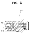
- a conventional particle concentration detection apparatus 90 of the transmittance type (Fig. 13) particles deposit on two surfaces, that is, a light-emitting surface 91 and a light-receiving surface 92, thus decreasing the amount of light received by a photosensor.
- a light-emitting surface 91 and a light-receiving surface 92 deposit on two surfaces, that is, a light-emitting surface 91 and a light-receiving surface 92, thus decreasing the amount of light received by a photosensor.
- the apparatus of the present invention is of the reflection type, the depth of the receiving portion for receiving the examination-undergoing liquid can be increased.
- the transmittance type the amount of transmission of light is decreased as the depth of the examination-undergoing liquid is enlarged.
- the cleaning members can be received in the receiving portion, so that the soil of the detection surface can be suppressed.
- the apparatus of the present invention is of the reflection light-measuring type, the presence of the cleaning members, as well as the presence of bubbles, will hardly affect the detection precision. Even if the presence of the cleaning members slightly affects the amount of the received light, the influence of the cleaning members can be made uniform by increasing the sampling time period T at the judgment portion, and therefore the measuring precision will not be affected.
- the particle concentration detection apparatus which is not lowered in sensitivity even for the liquid of a low light transmittance, and is hardly affected by non-particle foreign matters such as bubbles.
- this embodiment differs from the first embodiment mainly in that there are provided three detection surfaces 361 to 363 disposed in contact with an examination-undergoing liquid 8 for totally reflecting examination light 82 at boundary surfaces thereof, and that the detection surfaces 361 to 363 are inserted in and fixed to a vessel or a conduit or the like holding the examination-undergoing liquid 8.
- the direction of the optical path of the examination light 82 from a light source 111 is changed by the detection surfaces 361 to 363, and is incident on the photosensor 12 mounted on a board 66 having the light source 111 mounted thereon.
- the detection surfaces 361 to 363 are formed respectively on outer surfaces of a prism 16 housed in a projected portion 41.
- An aperture 181 through which the only examination light 82 advancing at a predetermined angle passes is provided in the optical path at the light-incident side of the prism 16, and an aperture 182 through which the only reflection light 83 at a predetermined angle passes is provided in the optical path at the light-outgoing side of the prism 16.
- the particle concentration detection apparatus 10 includes the projected portion 41 for being inserted in a vessel or a conduit or the like for holding the examination-undergoing liquid 8, and a fixing member 42 for inserting and threadedly fixing the projected portion 41 relative to the vessel or the conduit.
- a confining portion 43 for confining cleaning members 35 is provided on the projected portion 41, which covers the detection surfaces 361 to 363 and allows the examination-undergoing liquid 8 to freely pass therethrough. The cleaning members 35, caused to float by the movement of the examination-undergoing liquid 8, are received within the confining portion 43.
- the wavelength ⁇ of the examination light 82 is 940 nm
- the examination-undergoing liquid 8 is engine oil in a diesel engine
- a material includes FDS30, FD110, FF9, FD60 and NbFD15 which are productions of HOYA CORPORATION.
- a total reflection critical angle ⁇ c1 is 56° if the refractive index of the engine oil is 1.46, and is 58.5° if the refractive index of the engine oil is 1.50.
- the three detection surfaces 361 to 363 are formed on the outer surfaces of the prism 16 in such a manner that the angle between any two adjacent ones of these detection surfaces is 120°.
- the examination light 82 emitted from the light source 111 passes through the first aperture 181, and enters the prism 16, and is incident on the first detection surface 361 at an incidence angle ⁇ 1 of 60°.
- the examination light is totally reflected by the first detection surface, and is incident on the second detection surface 362 at an incidence angle of 60° to be again totally reflected by it, and then is incident on the third detection surface 363 at an incidence angle of 60°.
- the examination light 82 is again totally reflected by this third detection surface, and is incident on the photosensor 12 through the second aperture 182.
- the optical path is formed in this manner.
- the direction of the reflection light 83 incident on the photosensor 12 is opposite (that is, 180° different from) and parallel to the direction of the examination light 82 emitted from the light source 111, and the light source 111 and the photosensor 12 are juxtaposed on the board 66 in parallel relation to each other, and are disposed perpendicular to the board 66.
- Circuits components of a reference sensor and a judgment portion are also mounted on the board 66.
- the confining portion 43 for the cleaning members 35 is provided on the projected portion 41 in covering relation to the detection surfaces 361 to 363.
- the confining portion 43 is made of a metal net, and is of such a configuration that the cleaning members 35 can be moved effectively.
- An externally-threaded portion 421 is formed on the surface of the fixing member 42, and is threadedly engaged in a threaded hole formed in the vessel or the conduit (not shown) holding the examination-undergoing liquid 8, thereby attaching the particle concentration detection apparatus 10 to the associated equipment.
- the vessel or the conduit or the like is, for example, an engine oil passageway portion (such as a bracket of an oil filter) or an oil pan.
- reference numeral 40 denotes a housing of the particle concentration detection apparatus 10
- reference numeral 41 denotes an O-ring for liquid sealing.
- the examination light 82 is incident at an angle of 60° on each of the three detection surfaces 361 to 363 different from one another by 120°, thereby changing the direction of the optical path.
- the direction of the total reflection light 83 reaching the photosensor 12 is 180° opposite to the direction of the examination light 82 emitted from the light source 111.
- the light source 111 and the photosensor 12 can be juxtaposed or arranged totally parallel to each other, and can be mounted on the common board 66.
- the mounting angle of the light source 111 is different from that of the photosensor 12, and therefore they can not be mounted on the common board as shown in Figs. 1 and 3. Therefore, in this embodiment, the two members 111 and 12, as well as the circuit components of the judgment portion, can be mounted on the single board 66, and time and labor required for mounting the parts can be greatly reduced.
- the particle concentration detection apparatus of this embodiment can be directly installed to the vessel or the conduit holding the examination-undergoing liquid 8, through the fixing member 42, and therefore this apparatus does not need to be provided with a receiving portion (as at 30 in Fig. 1) or a conduit portion for receiving the examination-undergoing liquid 8, so that the number of the component parts is reduced. Besides, since this apparatus is attached to the vessel or the conduit or the like, the installation space is reduced.
- the apertures 181 and 182 are provided respectively on the light-incident side and light-outgoing side of the prism, the intrusion of noise light and scattered light can be avoided, and therefore the S/N ratio is improved, thus enhancing the precision.
- one detection surface 364 and two mirrors 371 and 372 are formed respectively on outer surfaces of a prism 17.
- examination light 82 emitted from a light source 111 is incident on an incident surface 171 of the prism 17, and then is reflected by the first mirror (plane mirror) 371, and is incident on the detection surface 364.
- the light is totally reflected by the detection surface 364, and is again reflected by the second mirror (plane mirror) 372, and then goes out from an outgoing surface 172, and is incident on a photosensor 12.
- Such material includes FF5 which is a production of HOYA CORPORATION.
- a total reflection critical angle ⁇ c is 67.8° if the refractive index of the engine oil is 1.46, and is 72° if the refractive index of the engine oil is 1.50.
- the incidence angle with respect to the detection surface 364 is more than a total reflection critical angle ⁇ c2 , and is 67.8° or 72° close to it.
- the examination light 82 emitted from the light source 111 is generally parallel to the reflection light 83 incident on the photosensor 12, and the light source 111 and the photosensor 12 are mounted on a common board 66.
- a reference photosensor 13 is mounted on the board 66 as shown in Fig. 10.
- the reference photosensor 13 is a photosensor for detecting the intensity of the examination light 82. According this, a change of intensity of emission of the light-emission source due to change of temperature, and a change of light-emission source with the passage of time can be cancelled, thereby improving an accuracy of measurement.
- Circuit components of a judgment portion are also mounted on the board 66.
- This embodiment differs from the second embodiment in that the first and third detection surfaces 361 and 363 (Fig. 8) of the prism 16 of the second embodiment are replaced by mirrors 373 and 374, respectively, as shown in Fig. 11.
- an optical path in the particle concentration detection apparatus of this embodiment is the same as that in the second embodiment, this embodiment is different from the second embodiment in that there is provided only one detection surface 365, and that the mirrors 373 and 374 are respectively plane mirrors not in contact with the examination-undergoing liquid.
- this embodiment differs from the third embodiment in that a prism 18 of a different shape is used, and that two mirrors 375 and 376 are mounted respectively on outer surfaces of the prism 18 to form such an optical path that examination light 82 can be reflected a plurality of times by each of these mirrors 375 and 376.
- the examination light 82 is reflected by the first and second mirrors 375 and 376, and is incident on a detection surface 366. Reflection light totally reflected by the detection surface 366 is reflected by the first mirror 375 and the second mirrors 376, and then is again reflected by the first mirror 375, and is incident on a photosensor 12.
- An light-incident/outgoing surface 181 of the prism 18 is a slanting surface not parallel to the detection surface 366, and a board 66 is disposed parallel to the light-incident/outgoing surface 181.
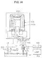
- This embodiment is directed to an oil deterioration detection apparatus which is installed to a bypass oil passageway connected to an oil circulating line of a gasoline engine.
- the oil circulating line 410 is a line for feeding oil to engine lubricating portions 414.
- An oil pan 411, an oil pump 412, an oil filter 413 and the engine lubricating portions 414 are provided on this line.
- Imide succinate serving as a detergent-dispersant is added to the oil.
- the oil pump 412 draws the oil stored in the oil pan 411, and feeds it to the oil filter 413.
- a control valve 412a provided parallel to the oil pump 412, is opened to communicate with a suction side of the oil pump 412, thereby adjusting the pressure of the delivery side to the predetermined level.
- the oil filter 413 is of the full-flow type, and therefore filters all of the oil discharged from the oil pump 412.
- a relief valve 413b is provided in the oil filter 413 in view of the filter clogging and a cold start of the engine.
- a filter element 413a used in the oil filter 413 is formed into a relatively coarse mesh (5 ⁇ m - 30 ⁇ m). The oil passes through the element 413a, and is supplied to the engine lubricating portions 414 through an oil line 410a.
- the engine lubricating portions 414 include bearings, sliding portions and the like in the engine which need to be reduced in friction and wear at their friction surfaces.
- the oil from the engine lubricating portions 414 passes through the oil filter 413, so that undissolved components of a size larger than a predetermined size, such as wear powder, combustion products and deteriorated components resulting from the oil itself, are removed by the filter 413, thereby purifying the oil. Thereafter, the purified oil is again fed to the engine lubricating portions 414.
- a predetermined size means a size of the mesh of the filter element 413a.
- a bypass oil line 410b branches from the oil circulating line 410 intermediate the delivery side of the oil filter 413 and the engine lubricating portions 414, and is connected to the oil pan 411.
- the oil deterioration detection apparatus of the present invention is provided on this bypass oil line 410b.
- the oil deterioration detection apparatus comprises a fine undissolved component-arresting filter 416, and a flow rate measurement portion 417 serving as an oil deterioration detection means.
- the oil deterioration detection apparatus cooperates with an engine control unit (ECU) 418 which is provided for the engine and an alarm lamp 419 to form an oil deterioration alarm apparatus.
- ECU engine control unit
- the fine undissolved component-arresting filter 416 has a mesh which is larger than micelles of the detergent-dispersant added to the oil, and is smaller than the mesh of the filter element 413a.
- the mesh of the arresting filter 416 is more than 1.5 ⁇ m (which is the size of the micelles formed by the imide succinate), and is smaller than the mesh (5 ⁇ m - 30 ⁇ m) of the element 413a.
- the mesh of the arresting filter 416 is preferably set to a value close to the size of the micelles.
- the flow rate measurement portion 417 is provided downstream of the fine undissolved component-arresting filter 416, and counts the pulse produced by a gear 417a rotated by the oil passed through the fine undissolved component-arresting filter 416 and outputs as the flow rate.
- the flow rate of the oil decreases with the increase of the amount of fine undissolved components arrested by the fine undissolved component-arresting filter 416, and therefore the amount of the fine undissolved components can be determined in view of the detected flow rate of the oil.
- the ECU 418 is equipped with an arithmetic and control circuit of a known construction, and inputs the pulses from the flow rate measurement portion 417 and feeds an output to the alarm lamp 419.
- the alarm lamp 419 is mounted on a dashboard (not shown) in front of a driver's seat of an automobile, and is lit in response to the output from the ECU 418. Instead of the alarm lamp 419, other alarm device such as an alarm buzzer may be used.
- a solid line represents the relation between the amount of the fine undissolved components, arrested by the fine undissolved component-arresting filter 416, and a mileage of the automobile.
- the fine undissolved components include those produced by the inclusion of wear powder, sand and fuel into the oil, those produced by the formation of combustion products and the oxidation of the base oil, and those produced by the consumption of additives.
- the n-pentane undissolved components can be all grasped, and therefore the oil deterioration condition can be accurately detected as well.
- the relation between the amount of n-pentane undissolved components and the mileage according to a commonly-used method "ASTM D 893B" is indicated by a broken line in Fig. 15.
- ASTM D 893B a commonly-used method
- the deposition micelles to be arrested and removed are formed as a result of deposition of the fine undissolved components on the micelles of imide succinate having a size of about 1.5 ⁇ m, and the deposition micelles have a size greater than the mesh of the filter. As a result, the fine undissolved components of a microscopic size, which cannot be removed by ordinary filters, can be removed.
- the ECU 418 judges whether or not the flow rate is below a predetermined flow rate.
- the predetermined flow rate is obtained by experientially finding the flow rate during the idling of the engine immediately before the fine undissolved components and the deposition micelles aggregate to become large. If the ECU 418 judges that the flow rate is below the predetermined level, it feeds an output to the alarm lamp 419 to tell the operator (driver) of this.
- the condition in which the flow rate is below the predetermined level coincides with the condition in which a predetermined amount of fine undissolved components are accumulated in the fine undissolved component-arresting filter 416, and if the oil is further continued to be used, the fine undissolved components and the deposition micelles aggregate to become large, so that the lubricating performance of the oil is lowered.
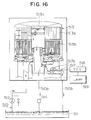
- the seventh embodiment is directed to an oil deterioration detection apparatus provided on an oil circulating line of a diesel engine.
- the oil circulating line 510 is a line for feeding oil to engine lubricating portions 514.
- An oil pan 511, an oil pump 512, an oil filter 513 and the engine lubricating portions 514 are provided on this line.
- imide succinate serving as a detergent-dispersant is added to the oil.
- the oil pan 511, the oil pump 512 and the engine lubricating portions 514 are similar to those of the sixth embodiment, and therefore explanation thereof will be omitted.
- the oil filter 513 is of the combination type in which a full-flow type and a bypass-flow type are juxtaposed. More specifically, a major part of the oil discharged from the oil pump 512 is filtered by a full-flow element 513a, and is fed to the engine lubricating portions 514 via an oil line 510a, whereas the remainder (part) of the oil is filtered by a bypass element 513b, and is returned to the oil pan 511 via an oil line 510b. As in the sixth embodiment, a relief valve 513c is mounted on the top of the oil filter 513.
- the full-flow element 513a used in the oil filter 513 has a relatively coarse mesh (5 ⁇ m - 30 ⁇ m), and the bypass element 513b has a fine mesh (2 ⁇ m - 10 ⁇ m). However, the filter mesh of the bypass element 513b is finer than that of the full-flow element 513a.
- the oil deterioration detection apparatus of the seventh embodiment comprises the bypass element 513a serving as a fine undissolved component-arresting filter, and a flow rate measurement portion 517 serving as an oil deterioration detection means.
- the oil deterioration detection apparatus cooperates with an ECU 518 and an alarm lamp 519 to form an oil deterioration alarm apparatus.
- the flow rate measurement portion 517, the ECU 518 and the alarm lamp 519 are similar to those of the sixth embodiment, and therefore explanation thereof will be omitted.
- the relation between the amount of fine undissolved components, arrested by the bypass element 513b, and the running distance is generally similar to that shown in Fig. 15.
- the deposition micelles to be arrested and removed are formed as a result of deposition of the fine undissolved components on the micelles of imide succinate having a size of about 1.5 ⁇ m, and the deposition micelles have a size greater than the filter mesh. As a result, the fine undissolved components of a microscopic size can be removed.
- the ECU 518 carries out a processing similar to that in the sixth embodiment, and properly judges a condition immediately before the lubricating performance of the oil is deteriorated, and causes the alarm lamp 519 to be lit, thereby telling the operator that the oil must be exchanged with fresh oil.
- the tendency of change of the amount of the fine undissolved components used as the oil deterioration index is the same with both the gasoline engine and the diesel engine. Therefore this can be used as the deterioration index common to the gasoline engine and the diesel engine, as described in the above embodiments.
- the flow rate measurement portion serving as the oil deterioration detection means may be replaced by a pressure sensor.
- the pressure of the oil passed the fine undissolved component-arresting filter decreases with the increase of the amount of the arrested fine undissolved components. Therefore, by detecting this pressure decrease, the amount of the fine undissolved components can be determined.
- the ECU feeds an output to the alarm lamp, so that the same effects as in the above embodiments can be obtained.
- the combination of the pressure sensor, the ECU and the alarm lamp may be replaced by a combination of a pressure switch and the alarm lamp.
- the amount of the fine undissolved components arrested by the fine undissolved component-arresting filter can be grasped more accurately. More specifically, where the output representative of the pressure is inputted to the ECU, the pressure is compensated by effecting calibration of a viscosity and etc., in accordance with the temperature of the oil, or the pressure is compensated by effecting calibration of the flow rate in accordance with the engine speed. By doing so, the amount of the fine undissolved components can be detected more accurately.
- the agent to be used is not limited to this material, and any other suitable material can be used in so far as it has such a nature as to uniformly disperse the fine undissolved components, such as sludges, in a stable manner.
- the mesh of the fine undissolved component-arresting filter should be larger than the size of the micelles of the detergent-dispersant to be used, and should be smaller than the mesh of the full-flow element.
- An apparatus for detecting the concentration of particles in a liquid (8) includes a light-emitting portion (11) for emitting examination light (82) which is totally reflected by a boundary surface (80) contiguous to the liquid to be examined, a photosensor (12) for receiving the totally-reflected light, a reference sensor (13) for directly receiving the examination light, and a judgment portion (20) for finding the reflectance from outputs of the two sensors to compute the particle concentration.
- the concentration of carbon particles is calculated, thereby judging the deterioration of the lubricating oil.
Landscapes
- Chemical & Material Sciences (AREA)
- Engineering & Computer Science (AREA)
- Health & Medical Sciences (AREA)
- Life Sciences & Earth Sciences (AREA)
- Immunology (AREA)
- Biochemistry (AREA)
- General Health & Medical Sciences (AREA)
- General Physics & Mathematics (AREA)
- Physics & Mathematics (AREA)
- Pathology (AREA)
- Analytical Chemistry (AREA)
- Chemical Kinetics & Catalysis (AREA)
- General Chemical & Material Sciences (AREA)
- Oil, Petroleum & Natural Gas (AREA)
- Food Science & Technology (AREA)
- Medicinal Chemistry (AREA)
- Mechanical Engineering (AREA)
- General Engineering & Computer Science (AREA)
- Investigating Or Analysing Materials By Optical Means (AREA)
Abstract
Description
- This invention relates to an oil deterioration detection apparatus, and also relates to an apparatus for detecting particles in a liquid.
- Attempts have heretofore been made to develop apparatus for detecting the deterioration of lubricating oil in an internal combustion engine and for telling or warning the operator (driver) of it. However, oil deterioration is caused by many factors, and therefore it has been necessary to detect many judgment indexes and to judge them synthetically to determine the oil deterioration. It is desirable to evaluate the lubricating performance of oil from a plurality of indexes such, for example, as (1) the production of n-pentane undissolved components due to the inclusion of wear powder, sand, fuel and etc., (2) the increase of viscosity due to the same factors, (3) the increase of the total acid number due to the development of combustion products and the oxidation of base oil, and (4) the reduction of the total basic number due to the consumption of additives. However, an apparatus capable of detecting all of these indexes has been found not practical from the viewpoint of costs.
- Therefore, relatively simple methods have been proposed as disclosed in Japanese Patent Unexamined Publication Nos. 63-266342 (Absorbance measurement method) and 3-142349 (Impedance measurement method), Japanese Patent Unexamined Publication No. 61-213749, Japanese Utility Model Unexamined Publication No. 62-193549 and Japanese Patent Unexamined Publication No. 3-111741 (Transmittance measurement method). With the conventional apparatuses, however, the judgment indexes for oil deterioration have not been proper, and therefore the warning was too early or too late, and any apparatus suited for practical use has not yet been known.
- Particularly in the type of apparatus using an optical method such as an absorbance measurement method and a transmittance measurement method, a light-incident surface and a light-outgoing surface are liable to be stained, and therefore it has been difficult to maintain high detection precision for a long period of time. In the type of apparatus in which an oil layer is interposed between an light-incident surface and a light-outgoing surface, the thickness of the oil layer greatly influences the detection precision, but it has been difficult to set the thickness of the oil layer to an optimum value because of the fact that foreign matters included in oil must be prevented from being jammed and of a limited assembling precision in the manufacture. Furthermore, in the type of apparatus using the optical method, it has also been difficult to effect an accurate detection since bubbles included in oil adversely affect the amount of transmitted light.
- With the above problems of the prior art in view, it is an object of this invention to provide a practical oil deterioration detection apparatus.
- Another object of the invention is to provide a practical oil deterioration detection apparatus in which in view of the fact that the condition of carbon particles included in oil accurately reflects oil deterioration, the oil deterioration is detected by detecting the condition of carbon particles included in the oil.
- A further object of this invention is to provide a practical oil deterioration detection apparatus in which the condition of carbon particles included in oil is detected by an optical method to thereby detect oil deterioration.
- A still further object of the invention is to provide an oil deterioration detection apparatus in which oil deterioration is detected by an optical method, and the distance of transmission of light in oil can be accurately set to a predetermined length, and the lowering of a detection precision due to stains on a light-incident surface and a light-outgoing surface can be suppressed.
- A further object of the invention is to provide an apparatus in which the size (diameter) of carbon particles included in oil can be detected with a relatively simple method.
- A further object of the invention is to provide an apparatus for detecting particles in a liquid, in which the particles included in the liquid can be detected with a high precision.
- A further object of the invention is to provide a particle detection apparatus in which particles included in a liquid can be detected using an optical method, and the distance of transmission of light in the liquid can be accurately set to a predetermined length, and besides the lowering of a detection precision due to stains on a light-incident surface and a light-outgoing surface can be suppressed.
- A further object of the invention is to provide a particle detection apparatus in which particles included in a liquid can be detected using an optical method, and the lowering of a detection precision due to a change in the amount of light from a light-emitting portion can be suppressed.
- A further object of the invention is to provide an oil deterioration detection apparatus, as well as an apparatus for detecting particles in a liquid, which can be easily installed.
- To this end, according to the present invention, there is provided an apparatus for detecting the concentration of particles in a liquid (hereinafter often referred to as "particle concentration detection apparatus), which comprises a light-emitting portion, disposed in contact with the liquid (hereinafter referred to as "examination-undergoing liquid) to be examined, for emitting examination light to be totally reflected by a boundary surface thereof, a photosensor for receiving the totally reflected light, a reference photosensor for directly receiving the examination light, and a judgment portion for finding a reflectance from output signals from the two photosensors and for calculating the particle concentration of the liquid from this reflectance.
- A first point to be most noted in the present invention is that the examination light emitted to the examination-undergoing liquid from the light-emitting portion is totally reflected by the boundary surface thereof.
- Namely, if the refractive index of the examination-undergoing liquid is represented by n₂, and the refractive index of the light-emitting portion (hereinafter referred to as "boundary portion") forming a detection surface in contact with the examination-undergoing liquid is represented by n₁, the position of a light source and the refractive index n₁ of the boundary portion are so determined that the angle ϑ₁ of incidence of the examination light is larger than the total reflection angle

- A second point to be noted in the present invention is that the photosensor is provided at such a position as to receive the totally reflected light, and that there is provided a reference photosensor for directly receiving the examination light.
- The judgment portion is an operation circuit which calculates the reflectance from the output signals of the two photosensors varying in accordance with the particle concentration, and judges the particle concentration of the examination-undergoing liquid from this reflectance.
- The particle concentration detection apparatus may be used as a lubrication oil deterioration apparatus for a diesel engine, which judges the lubrication oil deterioration from the carbon particles concentration.
- Preferably, there is provided a receiving portion for containing the examination-undergoing liquid, and cleaning members, which can be floated by movement of the examination-undergoing liquid, are included in the receiving portion.
- The cleaning members are floated by the movement (including convection) of the examination-undergoing liquid to collide with the detection surface. The repetition of collision prevents foreign matters from depositing on the detection surface, so that the hindrance to the entering of the examination light, as well as a change in the amount of the light received by the photosensor, is suppressed.
- Although there is a fear that the amount of the reflection light may be varied when such cleaning members are included in the liquid, such a disadvantage is eliminated by a method in which the time of measurement of the light is made longer than a certain time period, and the average value during that time period is used.
- Namely, the cleaning members float, and therefore variations of the frequency of intrusion of the cleaning members into the path of the light to be reflected, if the measurement time is made longer than a predetermined time period, can be almost cancelled.
- In a conventional particle concentration detection apparatus of the light-transmitting type, it is extremely difficult to include such cleaning members in a receiving portion.
- One reason for this is that the distance between a light-incident portion and a light-outgoing portion is extremely small with a liquid of a low transmittance. A second reason is that as a result of inclusion of the cleaning members, the transmitting light is intercepted, so that the amount of the received light varies.
- Preferably, there are provided a plurality of detection surfaces which are in contact with the examination-undergoing liquid, and cause the examination light to be totally reflected at their boundary surface, and there is formed such an optical path in which the examination light, emitted from the light source of the light-emitting portion, is totally reflected by the plurality of detection surfaces, and then reaches the photosensor.
- By thus providing the plurality of detection surfaces, the rate of change of the totally reflected light with respect to the examination-undergoing liquid is greatly increased.
- As described later in detail, the intensity of the totally reflected light at the detection surface varies (decreases) in accordance with the particle concentration of the examination-undergoing liquid. If the total reflection is effected a plurality of times at the plurality of detection surfaces, the rate of change of the totally reflected light is accumulated, and as a result the rate of change, which can not be easily detected by only one total reflection, can be increased into such a change rate as to be easily detected.
- The optical path, by which the total reflection is effected at the plurality of detection surfaces as described above, can be formed by arranging the plurality of detection surfaces at different angles, respectively, or by suitably providing mirrors or the like for changing the direction of the examination light.
- Preferably, a plurality of mirrors or the like are provided in the optical path leading from the light source to the photosensor, thereby changing the direction of the optical path in such a manner that the total reflection light can be incident on the photosensor mounted on a board having the light source mounted thereon.
- If the light source and the photosensor are thus mounted on the common board, the two members can be easily mounted during the assembling process since they are to be mounted on the common board, and only one board is needed, so that the cost can be reduced.
- Ordinary circuit components to be mounted on a board can be mounted on a common board since no limitation of an optical mounting angle is imposed on these components. On the other hand, the mounting angle of the light source and the photosensor is limited because of optical requirements, and the two are usually required to be mounted on different boards, respectively. Therefore, the two have been mounted on different boards, respectively, or have been mounted outside of the board having the circuit components mounted thereon. However, with the above arrangement, the above problem is overcome, thus enabling the two members to be mounted on a common board.
- More specifically, rays of the examination light incident on the detection surface is not parallel to rays of the total reflection light reflected by the detection surface, and the angle between the two light rays is 2ϑ₁ (ϑ₁ represents the angle of incidence of the examination light). Therefore, the mounting angle between the light source and the photosensor is also 2ϑ₁, and therefore they can not be mounted on a common board in parallel relation to each other (perpendicularly to the board).
- However, by changing the direction of the optical path of the examination light (the total reflection light) using the mirrors or the like as described above, the examination light emitted from the light source can be parallel to the total reflection light incident on the photosensor. As a result, the light source and the photosensor can be mounted on the common board in parallel relation to each other.
- Here, the above term "mirrors or the like" should be construed as including the detection surface itself in addition to a plane mirror and other mirrors, because the detection surface achieves the same reflection effect as a plane mirror does.
- A main portion of the optical path can be constituted by a prism, and the mirrors or the like for changing the direction of the examination light can be formed on outer surfaces of this prism.
- Namely, the prism has a plurality of outer surfaces intersecting one another, and these outer surfaces are suitably positioned at suitable angles, respectively, and mirrors or the like for reflecting the examination light are formed on the outer surfaces, respectively, so that the desired optical path can be formed.
- Preferably, apertures for allowing only those light rays, incident at a predetermined angle, to pass therethrough are provided in the optical path leading from the light source to the photosensor.
- Thanks to the provision of the apertures, disturbance light and noise light (in the examination light) entering at an angle difference from that of the desired examination light, and scattered light in the total reflection light can be removed. As a result, the S/N ratio of the particle concentration detection apparatus is increased, and the detection precision can be enhanced.
- For example, apertures are provided respectively in the optical path portion at the light-incident side of the prism and the optical path portion at the light-outgoing side of the prism.
- By providing the aperture at the light-incident side, the examination light can be incident on the detection surface at a predetermined angle, while shutting out the noise light.
- By providing the aperture at the light-outgoing side, only the regular total reflection light can be caused to be incident on the photosensor, while shutting out the disturbance light and the noise light.
- Preferably, in the particle concentration detection apparatus, there is provided a projected portion inserted in a vessel (container) or a conduit or the like for containing the examination-undergoing liquid, and there is provided a fixing member for inserting and fixing the projected portion relative to the vessel or the conduit, and the detection surface is formed on the projected portion.
- With this construction, the need for the receiving portion for receiving the examination-undergoing liquid, as well as a conduit for introducing the examination-undergoing liquid into the receiving portion, is obviated, and the number of the component parts is reduced. Since the vessel or the conduit or the like for containing the examination-undergoing liquid can be attached directly to the associated equipment, the particle concentration detection apparatus can be installed in a space-saving manner.
- Preferably, there is provided a confining portion for the cleaning members which portion allows the examination-undergoing liquid to freely flow therethrough.
- As described above, the cleaning members are caused to be floated by movement of the examination-undergoing liquid, and can prevent the detection surface from being soiled.
- As shown in a formula (1) (representing the index of the depth of entering of an evanescent wave) later described, in case that the wavelength λ of the examination light is made large, the angle ϑ₁ (ϑ₁ > ϑc) of incidence of the examination light is made small, and the refractive index of the prism is made low, the rate of change of the total reflection light with respect to the particle concentration, that is, the detection sensitivity, can be enhanced.
- For example, where the examination-undergoing liquid is lubricating oil in a diesel engine, the optical system may be constructed in such a manner that an LED or a semiconductor laser for emitting light of red or infrared wavelength (not less than 600 nm) is used as the light source, that the light-emitting portion forming the detection surface is made of glass or a resin capable of allowing light to transmit therethrough, and that the incidence angle ϑ₁ is set to a value close to the total reflection critical angle ϑc.
-
- Fig. 1 a view explanatory of an optical system of an oil deterioration detection apparatus of a first embodiment;
- Fig. 2 is an illustration explanatory of the processing of signals in the oil deterioration detection apparatus of the first embodiment;
- Fig. 3 is a front-elevational, cross-sectional view of the oil deterioration detection apparatus of the first embodiment;
- Figs. 4A to 4E are views explanatory of various configurations of a cleaning member in the oil deterioration detection apparatus of the first embodiment;
- Fig. 5 is a graph showing the relation between the particle concentration and the reflectance in an apparatus for detecting the concentration of particles in a liquid according to the present invention;
- Fig. 6 is an illustration explanatory of an evanescent wave;
- Fig. 7 is an illustration explanatory of the principle of the optical system of the particle concentration detection apparatus of the present invention;
- Fig. 8 is a cross-sectional view of an oil deterioration detection apparatus of a second embodiment;
- Fig. 9 is a cross-sectional view of an oil deterioration detection apparatus of a third embodiment;
- Fig. 10 is a cross-sectional view taken along the line X-X of Fig. 9, with a confining portion omitted;
- Fig. 11 is a cross-sectional view of an important portion of an optical system of an oil deterioration detection apparatus of a fourth embodiment;
- Fig. 12 is a cross-sectional view of an important portion of an optical system of an oil deterioration detection apparatus of a fifth embodiment;
- Fig. 13 is a view explanatory of a conventional oil deterioration detection apparatus;
- Fig. 14 is a view showing a general construction of a sixth embodiment;
- Fig. 15 is a graph showing the relation between the amount of fine undissolved components and a running distance; and
- Fig. 16 is a view showing a general construction of a seventh embodiment.
- An apparatus for detecting the concentration of particles in a liquid according to an embodiment of the present invention will now be described with reference to Figs. 1 to 4E. In this embodiment, the concentration of carbon particles in lubricating oil in a diesel engine is detected so as to judge deterioration of the lubricating oil.
- As shown in Figs. 1 and 2, an optical system of the carbon particle
concentration detection apparatus 10 of this embodiment comprises a light emitting portion 11 for emitting examination light 82 to be totally reflected by aboundary surface 80 contiguous to aliquid 8 to be examined, aphotosensor 12 for receiving reflection light 83 from the examination-undergoingliquid 8, areference photosensor 13 for directly receiving theexamination light 82, and ajudgment portion 20 for determining reflectance σ from output signals of the twophotosensors - The examination-undergoing
liquid 8 in this embodiment is lubricating oil in a diesel engine, and thejudgment portion 20 further judges the deterioration of the lubricating oil from the particle concentration σ. -
Cleaning members 35, caused to be floated by the movement of the examination-undergoingliquid 8, are received in a receivingportion 30, which has adetection surface 31 disposed in contact with the examination-undergoingliquid 8, for cleaning thedetection surface 31, theexamination light 82 being incident on thisdetection surface 31. - This embodiment will be described in further detail.
- The
examination light 82, emitted from a light source 111 of the light-emitting portion 11, advances in aprism 15, and is totally reflected on theboundary surface 80 contiguous to the examination-undergoingliquid 8, and thereflection light 83 is incident on thephotosensor 12. - More specifically, the relation, ϑ₁ > sin⁻¹(n₂/n₁), is established where n₁ represents the refractive index of the
prism 15, n₂ represents the refractive index of the examination-undergoingliquid 8, and ϑ₁ represents the angle of incidence of theexamination light 82. - The
reference photosensor 13 is mounted on one side portion of thedetection surface 31 of the receivingportion 30, and is in contact with theprism 15. Thereference photosensor 13 is a photosensor for detecting the intensity of theexamination light 82. According this, a change of intensity of emission of the light-emission source due to change of temperature, and a change of light-emission source with the passage of time can be cancelled, thereby improving an accuracy of measurement. - The receiving
portion 30 for holding the examination-undergoingliquid 8 therein has aflow inlet portion 301 for theliquid 8, a flow outlet portion (not shown) for theliquid 8, and thedetection surface 31 for theexamination light 82, as shown in Fig. 1. - A flow-
out prevention member 45 in the form of a metal net for preventing thecleaning members 35 from flowing out of the receivingportion 30 is provided in each of theflow inlet portion 301 and the flow outlet portion. The mesh of the flow-out prevention member 45 is smaller than the size of thecleaning members 35. - The
cleaning members 35, together with the examination-undergoingliquid 8, in the receivingportion 30 are made of fluoroplastics or the like so that they do not damage theprism 15, and are durable in the examination-undergoingliquid 8. They may be, for example, in the form of a spherical body having semi-spherical small recesses (Fig. 4A), a spherical body (Fig. 4B), a spherical body having small spherical projections (Fig. 4C), a regular tetrahedral body (Fig. 4D), or a body formed generally by combining two spherical bodies together (Fig. 4E). - Any of these cleaning
members 35 has such configuration and specific gravity that it can easily move in response to the movement of the examination-undergoingliquid 8. - As the material for the cleaning
member 35, other material than fluoroplastics, such as fluororubber, glass, ceramics and metal, can be used. Also, the cleaningmember 35 may be of a hollow so as to obtain the required specific gravity. - It is also preferred that the surface of the cleaning
member 35 should have a low light reflectance. To meet these requirements, the surface portion of the cleaning member may be formed of a material different from that of a core portion thereof. For example, a polytetrafluoroethylene ball having an iron core portion coated with polytetrafluoroethylene, or a fluororubber ball having an iron core portion coated with fluororubber can be used. - The whole of the particle
concentration detection apparatus 10 has a cross-sectional shape shown in Fig. 3. The optical members including theprism 15 are provided at a central portion of the apparatus, and afeed conduit 61 for the examination-undergoingliquid 8 is provided at below of theprism 15, and the receivingportion 30 communicated with a discharge conduit (not shown) disposed perpendicular to thefeed conduit 61. - A printed
circuit board 65, having thejudgment portion 20 mounted thereon, is provided at an upper portion of the apparatus. In Fig. 3, areference numeral 69 denotes an input/output connector for signals and power. - The examination-undergoing
liquid 8 flows through the receivingchamber 30 from thefeed conduit 61, and flows out from the discharge conduit (not shown). - The examination-undergoing
liquid 8 in the receivingportion 30 is in contact with theprism 15. - The
photosensor 12 and the light source 111 are mounted respectively on side surfaces of theprism 16, and the reference photosensor 13 (not shown in Fig. 3) is mounted on a bottom surface of theprism 15. - As shown in Fig. 2, the
judgment portion 20 comprises adriver circuit 21 for driving an LED (light source 111), asignal amplifier 22 for amplifying an output signal I₁ of thephotosensor 12 and an output signal I₀ of thereference photosensor 13, adivider circuit 23 for dividing an amplified output V₁ of the photosensor 12 by an amplified output V₀ of the reference photosensor 13 to obtain the reflectance σ, ajudgment circuit 24 for comparing the reflectance
driver circuit 25 for driving an alarm display device (not shown). Thejudgment circuit 24 may convert the reflectance σ into the particle concentration α in accordance with a characteristic diagram of Fig. 5, thus outputting it. - A
thermistor temperature gauge 26 is provided in the vicinity of theboundary surface 80 of theprism 15, and output signal T of the temperature gauge is inputted to theabove driver circuit 21. - The
driver circuit 21 operates the light source 111 only when the temperature output signal T is within a predetermined range between T₁ and T₂. - Therefore, the particle concentration is measured only when the temperature of the lubricating oil is within the predetermined range, and then an error due to a temperature change of the lubricating oil hardly occurs.
- The output signal I₁ of the photosensor 12 receiving the
reflection light 83 is amplified, and then is divided by the output signal I₀ of the reference photosensor 13 to be converted into the reflectance σ. Therefore, even if the intensity of the light from the light source 111 is varied, a detection error will not occur. - Next, the operation of the
cleaning members 35 will now be described. - The examination-undergoing
liquid 8 flows in a predetermined direction, and convection is also produced within the receivingportion 30. On the other hand, thecleaning members 35 are confined within the receivingportion 30 by the flow-out prevention member 45. Therefore, thecleaning members 35 are caused to move in the receivingportion 30 by the force of the examination-undergoingliquid 8. Therefore, thecleaning members 35 collide on the detection surface 31 (which defines the boundary surface between theprism 15 and the examination-undergoing liquid 8) to destroy and separate soils from thedetection surface 31. - The
cleaning members 35 also serve to prevent soils from growing on the detection surfaces. - In this embodiment, without providing any special soil-removing mechanism, such as a wiper, on the
detection surface 31, soils on thedetection surface 31 can be removed with the relatively simple construction in which thecleaning members 35 are received in the receivingportion 30. - As described above, in this embodiment, there is provided the particle
concentration detection apparatus 10 in which the boundary portion (detection surface 31) between theprism 15 and the examination-undergoingliquid 8 can be prevented from being soiled, and also soils on this boundary portion can be removed. - If the movement of the liquid in the flow path is promoted, for example, by a means for intermittently applying an impulse stream to the examination-undergoing
liquid 8, this is more effective. - The particle
concentration detection apparatus 10 of this embodiment measures the totally-reflectedlight 83, and detects the particle concentration, and therefore can achieve the purpose regardless of whether the light transmittance of the examination-undergoingliquid 8 is high or low. - Therefore, even for the examination-undergoing
liquid 8 of a low light transmittance, the particle concentration can be measured precisely. - Besides, even if non-particle foreign matters such as bubbles exit in the examination-undergoing
liquid 8, this hardly affects the measurement, as described above. - Furthermore, since the soil of the
detection surface 31 can be suppressed by thecleaning members 35, an error due to the soil of thedetection surface 31 hardly occurs. - As described above, in this embodiment, there is provided the particle
concentration detection apparatus 10 which is not lowered in sensitivity even for the liquid of a low light transmittance, and is hardly affected by non-particle foreign matters such as bubbles, and can suppress an error due to the soil of thedetection surface 31. - In this embodiment, although the
thermistor temperature gauge 26 is provided in the vicinity of the examination-undergoingliquid 8 so as to measure the particle concentration of the examination-undergoing liquid in the predetermined temperature range, thethermistor temperature gauge 26 may be provided near to the light source 111 so as to suppress the operating ambient temperature of the LED (light source 111) to below a predetermined temperature (for example, 100°C), thereby prolonging the lifetime of the LED. - A measurement principle will be described hereinafter.
- As shown in Fig. 6, when the light advances from a first medium 801 with a refractive index n₁ to a
second medium 802 with a refractive index n₂ at an angle ϑ₁ larger than a total reflection critical angle ϑc, the light will not enter thesecond medium 802 with the refractive index n₂, but will be totally reflected. However, upon observing this phenomenon in detail, the reflection light goes out from a point B apart from a point A of incidence by a distance G. - Namely, the light once enters the
second medium 802, and goes out from the point B as shown in a broken line in Fig. 6. This entering light is called "evanescent wave", and the gap G is called "Goos-Hänchen shift". - If a solid
foreign matter 81 such as carbon exists in thesecond medium 802, the evanescent wave is subjected to absorption and scattering, so that the intensity of the totally reflected light decreases as shown in Fig. 7. - Incidentally, the depth of entering of the light into the
second medium 802 varies depending on a wavelength λ of the light, the refractive indexes n₁ and n₂ of themediums

The greater the depth D of entering of the evanescent wave is, the larger the absorption and scattering (caused by the presence of the solid foreign matter 81) are, and therefore the degree of change (decrease) (i.e., rate of change) of the totally reflected light increases. - In the present invention, the concentration of the particles in the examination-undergoing liquid is detected utilizing the above phenomenon.
- Namely, the
reflection light 83, totally reflected by the boundary surface contiguous to the examination-undergoing liquid, is attenuated in proportion to the particle concentration of the liquid, as shown in Fig. 5, and therefore the particle concentration of the examination-undergoing liquid can be detected by the degree of decrease of the intensity of the reflection light, that is, the change of the reflectance. - In this case, in order that the number of particles in the liquid up to the depth

- In the present invention, the reflection light from the examination-undergoing liquid is detected so as to detect the particle concentration, and therefore this detection is not influenced by whether the light transmittance of the examination-undergoing liquid is high or low. Therefore, the sensitivity is not lowered at all even for the examination-undergoing liquid of a low transmittance.
- Besides, even if bubbles or the like are present in the examination-undergoing liquid, the evanescent wave is hardly affected. Namely, the depth δ of entering of the evanescent wave is extremely shallow, ant therefore the probability that the evanescent wave impinges on a bubble is extremely low, and even if the evanescent wave impinges on a non-particle foreign matter such as a bubble, this wave will hardly be scattered by a bubble.
- In a conventional particle
concentration detection apparatus 90 of the transmittance type (Fig. 13), particles deposit on two surfaces, that is, a light-emittingsurface 91 and a light-receivingsurface 92, thus decreasing the amount of light received by a photosensor. In the present invention, however, there is provided only one detection surface, and therefore such adverse effect can be reduced to a half level. - Since the apparatus of the present invention is of the reflection type, the depth of the receiving portion for receiving the examination-undergoing liquid can be increased. In the transmittance type, the amount of transmission of light is decreased as the depth of the examination-undergoing liquid is enlarged. With this construction of the present invention, the cleaning members can be received in the receiving portion, so that the soil of the detection surface can be suppressed.
- Furthermore, since the apparatus of the present invention is of the reflection light-measuring type, the presence of the cleaning members, as well as the presence of bubbles, will hardly affect the detection precision. Even if the presence of the cleaning members slightly affects the amount of the received light, the influence of the cleaning members can be made uniform by increasing the sampling time period T at the judgment portion, and therefore the measuring precision will not be affected.
- As described above, in the present invention, there is provided the particle concentration detection apparatus which is not lowered in sensitivity even for the liquid of a low light transmittance, and is hardly affected by non-particle foreign matters such as bubbles.
- As shown in Fig. 8, this embodiment differs from the first embodiment mainly in that there are provided three
detection surfaces 361 to 363 disposed in contact with an examination-undergoingliquid 8 for totally reflecting examination light 82 at boundary surfaces thereof, and that the detection surfaces 361 to 363 are inserted in and fixed to a vessel or a conduit or the like holding the examination-undergoingliquid 8. - The direction of the optical path of the examination light 82 from a light source 111 is changed by the detection surfaces 361 to 363, and is incident on the photosensor 12 mounted on a
board 66 having the light source 111 mounted thereon. - The detection surfaces 361 to 363 are formed respectively on outer surfaces of a
prism 16 housed in a projectedportion 41. - An
aperture 181 through which the only examination light 82 advancing at a predetermined angle passes is provided in the optical path at the light-incident side of theprism 16, and anaperture 182 through which the only reflection light 83 at a predetermined angle passes is provided in the optical path at the light-outgoing side of theprism 16. - As shown in Fig. 8, the particle
concentration detection apparatus 10 includes the projectedportion 41 for being inserted in a vessel or a conduit or the like for holding the examination-undergoingliquid 8, and a fixingmember 42 for inserting and threadedly fixing the projectedportion 41 relative to the vessel or the conduit. A confiningportion 43 for confiningcleaning members 35 is provided on the projectedportion 41, which covers the detection surfaces 361 to 363 and allows the examination-undergoingliquid 8 to freely pass therethrough. Thecleaning members 35, caused to float by the movement of the examination-undergoingliquid 8, are received within the confiningportion 43. - In this embodiment, the wavelength λ of the
examination light 82 is 940 nm, and the examination-undergoingliquid 8 is engine oil in a diesel engine, and its refractive index n₂ is 1.48 (at λ = 940 nm). - The
prism 16 may be made of a material whose refractive index n₁ is 1.73 or more (at λ = 940 nm) and whose chemical resistance is excellent. Such material includes FDS30, FD110, FF9, FD60 and NbFD15 which are productions of HOYA CORPORATION. A total reflection critical angle ϑc1 is 56° if the refractive index of the engine oil is 1.46, and is 58.5° if the refractive index of the engine oil is 1.50. - The three
detection surfaces 361 to 363 are formed on the outer surfaces of theprism 16 in such a manner that the angle between any two adjacent ones of these detection surfaces is 120°. - The examination light 82 emitted from the light source 111 passes through the
first aperture 181, and enters theprism 16, and is incident on thefirst detection surface 361 at an incidence angle ϑ₁ of 60°. - The examination light is totally reflected by the first detection surface, and is incident on the
second detection surface 362 at an incidence angle of 60° to be again totally reflected by it, and then is incident on thethird detection surface 363 at an incidence angle of 60°. Theexamination light 82 is again totally reflected by this third detection surface, and is incident on the photosensor 12 through thesecond aperture 182. Thus, the optical path is formed in this manner. - As will be appreciated from Fig. 8, the direction of the reflection light 83 incident on the
photosensor 12 is opposite (that is, 180° different from) and parallel to the direction of the examination light 82 emitted from the light source 111, and the light source 111 and the photosensor 12 are juxtaposed on theboard 66 in parallel relation to each other, and are disposed perpendicular to theboard 66. - Circuits components of a reference sensor and a judgment portion (not shown) are also mounted on the
board 66. - The confining
portion 43 for thecleaning members 35 is provided on the projectedportion 41 in covering relation to the detection surfaces 361 to 363. The confiningportion 43 is made of a metal net, and is of such a configuration that thecleaning members 35 can be moved effectively. - An externally-threaded
portion 421 is formed on the surface of the fixingmember 42, and is threadedly engaged in a threaded hole formed in the vessel or the conduit (not shown) holding the examination-undergoingliquid 8, thereby attaching the particleconcentration detection apparatus 10 to the associated equipment. - The vessel or the conduit or the like is, for example, an engine oil passageway portion (such as a bracket of an oil filter) or an oil pan.
- In Fig. 8,
reference numeral 40 denotes a housing of the particleconcentration detection apparatus 10, andreference numeral 41 denotes an O-ring for liquid sealing. - Advantages of this embodiment will now be described.
- In the particle concentration detection apparatus of this embodiment, there are provided the three
detection surfaces 361 to 363, and the totally reflected light at each of the threedetection surfaces 361 to 363 is changed (decreased) in accordance with the particle concentration of the liquid. Therefore, the rate of change of the amount of received light corresponding to the particle concentration detected by thephotosensor 12 is increased generally algebraically, as compared with the case where only one detection surface is provided. - As a result, the sensitivity of detection of the particle concentration is greatly enhanced.
- The
examination light 82 is incident at an angle of 60° on each of the threedetection surfaces 361 to 363 different from one another by 120°, thereby changing the direction of the optical path. As a result, the direction of the total reflection light 83 reaching thephotosensor 12 is 180° opposite to the direction of the examination light 82 emitted from the light source 111. - Therefore, the light source 111 and the photosensor 12 can be juxtaposed or arranged totally parallel to each other, and can be mounted on the
common board 66. In the first embodiment, the mounting angle of the light source 111 is different from that of thephotosensor 12, and therefore they can not be mounted on the common board as shown in Figs. 1 and 3. Therefore, in this embodiment, the twomembers 111 and 12, as well as the circuit components of the judgment portion, can be mounted on thesingle board 66, and time and labor required for mounting the parts can be greatly reduced. - The particle concentration detection apparatus of this embodiment can be directly installed to the vessel or the conduit holding the examination-undergoing
liquid 8, through the fixingmember 42, and therefore this apparatus does not need to be provided with a receiving portion (as at 30 in Fig. 1) or a conduit portion for receiving the examination-undergoingliquid 8, so that the number of the component parts is reduced. Besides, since this apparatus is attached to the vessel or the conduit or the like, the installation space is reduced. - Since the
apertures - In this embodiment, as shown in Fig. 9, one
detection surface 364 and twomirrors prism 17. - More specifically, examination light 82 emitted from a light source 111 is incident on an
incident surface 171 of theprism 17, and then is reflected by the first mirror (plane mirror) 371, and is incident on thedetection surface 364. - The light is totally reflected by the
detection surface 364, and is again reflected by the second mirror (plane mirror) 372, and then goes out from anoutgoing surface 172, and is incident on aphotosensor 12. - The
prism 17 may be made of a material whose refractive index n₁ is 1.51 or more (at λ = 940 nm) and whose chemical resistance is excellent. Such material includes FF5 which is a production of HOYA CORPORATION. A total reflection critical angle ϑc is 67.8° if the refractive index of the engine oil is 1.46, and is 72° if the refractive index of the engine oil is 1.50. - The incidence angle with respect to the
detection surface 364 is more than a total reflection critical angle ϑc2, and is 67.8° or 72° close to it. - The examination light 82 emitted from the light source 111 is generally parallel to the reflection light 83 incident on the
photosensor 12, and the light source 111 and the photosensor 12 are mounted on acommon board 66. - A
reference photosensor 13 is mounted on theboard 66 as shown in Fig. 10. Thereference photosensor 13 is a photosensor for detecting the intensity of theexamination light 82. According this, a change of intensity of emission of the light-emission source due to change of temperature, and a change of light-emission source with the passage of time can be cancelled, thereby improving an accuracy of measurement. Circuit components of a judgment portion (not shown) are also mounted on theboard 66. - This embodiment differs from the second embodiment in that the first and third detection surfaces 361 and 363 (Fig. 8) of the
prism 16 of the second embodiment are replaced bymirrors - Namely, although an optical path in the particle concentration detection apparatus of this embodiment is the same as that in the second embodiment, this embodiment is different from the second embodiment in that there is provided only one
detection surface 365, and that themirrors - As shown in Fig. 12, this embodiment differs from the third embodiment in that a
prism 18 of a different shape is used, and that twomirrors prism 18 to form such an optical path that examination light 82 can be reflected a plurality of times by each of thesemirrors - Namely, as shown in Fig. 12, the
examination light 82 is reflected by the first andsecond mirrors detection surface 366. Reflection light totally reflected by thedetection surface 366 is reflected by thefirst mirror 375 and thesecond mirrors 376, and then is again reflected by thefirst mirror 375, and is incident on aphotosensor 12. - An light-incident/
outgoing surface 181 of theprism 18 is a slanting surface not parallel to thedetection surface 366, and aboard 66 is disposed parallel to the light-incident/outgoing surface 181. - This embodiment is directed to an oil deterioration detection apparatus which is installed to a bypass oil passageway connected to an oil circulating line of a gasoline engine.
- As shown in Fig. 14, the
oil circulating line 410 is a line for feeding oil toengine lubricating portions 414. An oil pan 411, anoil pump 412, anoil filter 413 and theengine lubricating portions 414 are provided on this line. Imide succinate serving as a detergent-dispersant is added to the oil. - The
oil pump 412 draws the oil stored in the oil pan 411, and feeds it to theoil filter 413. When the pressure at a delivery side of theoil pump 412 exceeds a predetermined level, a control valve 412a, provided parallel to theoil pump 412, is opened to communicate with a suction side of theoil pump 412, thereby adjusting the pressure of the delivery side to the predetermined level. - The
oil filter 413 is of the full-flow type, and therefore filters all of the oil discharged from theoil pump 412. Arelief valve 413b is provided in theoil filter 413 in view of the filter clogging and a cold start of the engine. Afilter element 413a used in theoil filter 413 is formed into a relatively coarse mesh (5 µm - 30 µm). The oil passes through theelement 413a, and is supplied to theengine lubricating portions 414 through anoil line 410a. - The
engine lubricating portions 414 include bearings, sliding portions and the like in the engine which need to be reduced in friction and wear at their friction surfaces. - The oil from the
engine lubricating portions 414 passes through theoil filter 413, so that undissolved components of a size larger than a predetermined size, such as wear powder, combustion products and deteriorated components resulting from the oil itself, are removed by thefilter 413, thereby purifying the oil. Thereafter, the purified oil is again fed to theengine lubricating portions 414. Here, the term "predetermined size" means a size of the mesh of thefilter element 413a. - A
bypass oil line 410b branches from theoil circulating line 410 intermediate the delivery side of theoil filter 413 and theengine lubricating portions 414, and is connected to the oil pan 411. The oil deterioration detection apparatus of the present invention is provided on thisbypass oil line 410b. - The oil deterioration detection apparatus comprises a fine undissolved component-arresting
filter 416, and a flowrate measurement portion 417 serving as an oil deterioration detection means. The oil deterioration detection apparatus cooperates with an engine control unit (ECU) 418 which is provided for the engine and analarm lamp 419 to form an oil deterioration alarm apparatus. - The fine undissolved component-arresting
filter 416 has a mesh which is larger than micelles of the detergent-dispersant added to the oil, and is smaller than the mesh of thefilter element 413a. In this embodiment, since imide succinate is used as the detergent-dispersant, the mesh of the arrestingfilter 416 is more than 1.5 µm (which is the size of the micelles formed by the imide succinate), and is smaller than the mesh (5 µm - 30 µm) of theelement 413a. In order to arrest the fine undissolved components more effectively, the mesh of the arrestingfilter 416 is preferably set to a value close to the size of the micelles. - The flow
rate measurement portion 417 is provided downstream of the fine undissolved component-arrestingfilter 416, and counts the pulse produced by agear 417a rotated by the oil passed through the fine undissolved component-arrestingfilter 416 and outputs as the flow rate. The flow rate of the oil decreases with the increase of the amount of fine undissolved components arrested by the fine undissolved component-arrestingfilter 416, and therefore the amount of the fine undissolved components can be determined in view of the detected flow rate of the oil. - The
ECU 418 is equipped with an arithmetic and control circuit of a known construction, and inputs the pulses from the flowrate measurement portion 417 and feeds an output to thealarm lamp 419. - The
alarm lamp 419 is mounted on a dashboard (not shown) in front of a driver's seat of an automobile, and is lit in response to the output from theECU 418. Instead of thealarm lamp 419, other alarm device such as an alarm buzzer may be used. - In a graph of Fig. 15, a solid line represents the relation between the amount of the fine undissolved components, arrested by the fine undissolved component-arresting
filter 416, and a mileage of the automobile. As is clear from this graph, the amount of the fine undissolved components increases generally linearly with the increase of the mileage. The fine undissolved components include those produced by the inclusion of wear powder, sand and fuel into the oil, those produced by the formation of combustion products and the oxidation of the base oil, and those produced by the consumption of additives. Therefore, using the amount of these fine undissolved components as an index, the n-pentane undissolved components, the viscosity and the increase of the total acid value, and the decrease of the total basic value (which are conventional deterioration indexes) can be all grasped, and therefore the oil deterioration condition can be accurately detected as well. As a comparative example, the relation between the amount of n-pentane undissolved components and the mileage according to a commonly-used method "ASTM D 893B" is indicated by a broken line in Fig. 15. As is clear from this graph, the amount of the n-pentane undissolved components can not be detected before the mileage reaches a certain value, and therefore this is not the index for accurately detecting the oil deterioration condition. - Next, the operation of the sixth embodiment will now be described.
- When fine undissolved components such as sludges are produced in the oil, these components adhere to the micelles, formed by imide succinate, to form fine undissolved component-deposited micelles (hereinafter referred to as "deposition micelles"), and these are arrested and removed by the fine undissolved component-arresting
filter 416. Namely, the deposition micelles to be arrested and removed are formed as a result of deposition of the fine undissolved components on the micelles of imide succinate having a size of about 1.5 µm, and the deposition micelles have a size greater than the mesh of the filter. As a result, the fine undissolved components of a microscopic size, which cannot be removed by ordinary filters, can be removed. - The
ECU 418 judges whether or not the flow rate is below a predetermined flow rate. Here, the predetermined flow rate is obtained by experientially finding the flow rate during the idling of the engine immediately before the fine undissolved components and the deposition micelles aggregate to become large. If theECU 418 judges that the flow rate is below the predetermined level, it feeds an output to thealarm lamp 419 to tell the operator (driver) of this. The condition in which the flow rate is below the predetermined level coincides with the condition in which a predetermined amount of fine undissolved components are accumulated in the fine undissolved component-arrestingfilter 416, and if the oil is further continued to be used, the fine undissolved components and the deposition micelles aggregate to become large, so that the lubricating performance of the oil is lowered. - Advantageous effects of the sixth embodiment will be described.
- (1) The n-pentane undissolved components, the viscosity and the increase of the total acid value, and the decrease of the total basic value (which are conventional deterioration indexes) can be all grasped by the amount of the fine undissolved components which is used here as the deterioration index. The amount of the fine undissolved components increases generally linearly in proportion of a time period of use of the oil. Therefore, in this embodiment, the oil deterioration condition can be accurately detected.
- (2) The amount of the fine undissolved components can be easily detected by measuring the rate of flow of the oil through the fine undissolved component-arresting
filter 16 by the flowrate measurement portion 17. Therefore, the apparatus can be simplified in construction. - (3) The operator exchanges the oil when the alarm lamp 19 mounted on the dashboard is lit, and thus the oil can be exchanged with fresh oil immediately before the lubricating performance of the oil is lowered. Therefore, there is no risk that a burden is imposed on the engine lubricating portions 14, thereby enhancing the durability of the engine.
- Next, a seventh embodiment will now be described with reference to Fig. 16. The seventh embodiment is directed to an oil deterioration detection apparatus provided on an oil circulating line of a diesel engine.
- The
oil circulating line 510 is a line for feeding oil toengine lubricating portions 514. Anoil pan 511, anoil pump 512, anoil filter 513 and theengine lubricating portions 514 are provided on this line. As in the sixth embodiment, imide succinate serving as a detergent-dispersant is added to the oil. - The
oil pan 511, theoil pump 512 and theengine lubricating portions 514 are similar to those of the sixth embodiment, and therefore explanation thereof will be omitted. - The
oil filter 513 is of the combination type in which a full-flow type and a bypass-flow type are juxtaposed. More specifically, a major part of the oil discharged from theoil pump 512 is filtered by a full-flow element 513a, and is fed to theengine lubricating portions 514 via anoil line 510a, whereas the remainder (part) of the oil is filtered by abypass element 513b, and is returned to theoil pan 511 via anoil line 510b. As in the sixth embodiment, arelief valve 513c is mounted on the top of theoil filter 513. The full-flow element 513a used in theoil filter 513 has a relatively coarse mesh (5 µm - 30 µm), and thebypass element 513b has a fine mesh (2 µm - 10 µm). However, the filter mesh of thebypass element 513b is finer than that of the full-flow element 513a. - A major part of the oil from the
engine lubricating portions 514 through theoil pan 511 and theoil pump 512 passes through the full-flow element 513a of theoil filter 513, so that undissolved components of a size larger than the filter mesh of thiselement 513a, such as wear powder, combustion products and deteriorated components resulting from the oil itself, are removed by thiselement 513a, thereby purifying the oil. Thereafter, the purified oil is fed through theoil line 510a to theengine lubricating portions 514. On the other hand, the remainder of the oil from theoil pan 511 and theoil pump 512 passes through thebypass element 513a, so that fine undissolved components are removed by this element, and then returned to theoil pan 511 via thebypass oil line 510b. - The oil deterioration detection apparatus of the seventh embodiment comprises the
bypass element 513a serving as a fine undissolved component-arresting filter, and a flowrate measurement portion 517 serving as an oil deterioration detection means. The oil deterioration detection apparatus cooperates with anECU 518 and analarm lamp 519 to form an oil deterioration alarm apparatus. The flowrate measurement portion 517, theECU 518 and thealarm lamp 519 are similar to those of the sixth embodiment, and therefore explanation thereof will be omitted. The relation between the amount of fine undissolved components, arrested by thebypass element 513b, and the running distance is generally similar to that shown in Fig. 15. - Next, the operation of the seventh embodiment will now be described.
- When fine undissolved components such as carbon sludges are produced in the oil, these components form deposition micelles, and are arrested and removed by the
bypass element 513b. Namely, the deposition micelles to be arrested and removed are formed as a result of deposition of the fine undissolved components on the micelles of imide succinate having a size of about 1.5 µm, and the deposition micelles have a size greater than the filter mesh. As a result, the fine undissolved components of a microscopic size can be removed. - The
ECU 518 carries out a processing similar to that in the sixth embodiment, and properly judges a condition immediately before the lubricating performance of the oil is deteriorated, and causes thealarm lamp 519 to be lit, thereby telling the operator that the oil must be exchanged with fresh oil. - Advantageous effects of the seventh embodiment are generally the same as those of the sixth embodiment, and therefore explanation thereof will be omitted.
- The tendency of change of the amount of the fine undissolved components used as the oil deterioration index is the same with both the gasoline engine and the diesel engine. Therefore this can be used as the deterioration index common to the gasoline engine and the diesel engine, as described in the above embodiments.
- The present invention is not limited by the above embodiments, and various modifications can be made without departing from the scope of the invention.
- For example, the flow rate measurement portion serving as the oil deterioration detection means may be replaced by a pressure sensor. In this case, the pressure of the oil passed the fine undissolved component-arresting filter decreases with the increase of the amount of the arrested fine undissolved components. Therefore, by detecting this pressure decrease, the amount of the fine undissolved components can be determined. In the case of the oil deterioration alarm apparatus, when the detected pressure goes below a predetermined level, the ECU feeds an output to the alarm lamp, so that the same effects as in the above embodiments can be obtained. The combination of the pressure sensor, the ECU and the alarm lamp may be replaced by a combination of a pressure switch and the alarm lamp.
- As another alternative, if the temperature of the oil and an engine speed are detected and inputted to the ECU so as to compensate the flow rate detected by the flow rate measurement portion or the pressure detected by the pressure sensor, the amount of the fine undissolved components arrested by the fine undissolved component-arresting filter can be grasped more accurately. More specifically, where the output representative of the pressure is inputted to the ECU, the pressure is compensated by effecting calibration of a viscosity and etc., in accordance with the temperature of the oil, or the pressure is compensated by effecting calibration of the flow rate in accordance with the engine speed. By doing so, the amount of the fine undissolved components can be detected more accurately.
- Although imide succinate is used as the detergent-dispersant in the above embodiments, the agent to be used is not limited to this material, and any other suitable material can be used in so far as it has such a nature as to uniformly disperse the fine undissolved components, such as sludges, in a stable manner.
- In this case, also, the mesh of the fine undissolved component-arresting filter should be larger than the size of the micelles of the detergent-dispersant to be used, and should be smaller than the mesh of the full-flow element.
- An apparatus for detecting the concentration of particles in a liquid (8) includes a light-emitting portion (11) for emitting examination light (82) which is totally reflected by a boundary surface (80) contiguous to the liquid to be examined, a photosensor (12) for receiving the totally-reflected light, a reference sensor (13) for directly receiving the examination light, and a judgment portion (20) for finding the reflectance from outputs of the two sensors to compute the particle concentration. In case that the liquid to be examined is lubricating oil of an engine, the concentration of carbon particles is calculated, thereby judging the deterioration of the lubricating oil.
Claims (20)
- An apparatus for detecting a deterioration of oil (8), comprising sensor means (11, 12, 417, 417a, 517, 517a) for detecting a condition of carbon particles in the oil and for outputting a signal representative of the fact that the concentration of the carbon particles is more than a predetermined level indicative of the deterioration of the oil performance or the fact that the particle size of the carbon particles is more than a predetermined particle size indicative of the deterioration of the oil performance.
- Apparatus according to Claim 1, wherein said sensor means is an optical sensor for detecting the intensity of light transmitted through the oil, which is changed in accordance with the concentration of the carbon particles in said oil.
- Apparatus according to Claim 2, wherein said sensor comprises:
a light-emitting portion (11) for emitting the light (82) toward the oil;
a photosensor (12) for receiving the light (83) transmitted through the oil and for outputting a signal corresponding to the amount of the received light; and
cleaning members (35) which are moved by the flow of the oil, and are capable of bringing into contact with a surface (80, 361, 362, 364) of incidence of the light from said light-emitting portion and a surface (80, 363, 364) of outgoing of the light toward said sensor. - Apparatus according to Claim 3, wherein said sensor comprises a prism member (15, 16, 17, 18) having a boundary surface (80, 361, 362, 363, 364) forming said incidence surface and said outgoing surface, and wherein said light-emitting portion emits the light toward said boundary surface and said photosensor receives the light reflected by said boundary surface with Goos-Hänchen shift.
- Apparatus according to Claim 4, wherein said sensor includes a housing (40) receiving said light-emitting portion, said photosensor and said prism member therein, said housing having a projected portion (41) which is to be threaded to a container or a conduit holding the oil, and through which the oil is introduced to said boundary surface of said prism member.
- Apparatus according to Claim 3, wherein said sensor further comprises a reference photosensor (13) for directly receiving the light emitted from said light-emitting portion.
- Apparatus according to Claim 3, wherein there are provided flow-out prevention members (43, 45) which prevent said cleaning members from flowing away from the vicinity of said incidence surface and said outgoing surface while allowing the oil to flow in the vicinity of said incidence surface and said outgoing surface.
- Apparatus according to Claim 2, further comprising means (20) for judging that the concentration of the carbon particles in the oil exceeds the predetermined concentration indicative of the deterioration of the oil performance when the output signal from said sensor means exceeds a predetermined value.
- Apparatus according to Claim 6, further comprising:
means (24) for judging that the concentration of the carbon particles in the oil exceeds the predetermined concentration indicative of the deterioration of the oil performance when the output signal from said photosensor exceeds a predetermined value; and
means (22) for compensating a change of the output signal of said photosensor, caused by a change of the amount of the light emitted from said light-emitting portion, in accordance with an output signal from said reference sensor. - Apparatus according to Claim 1, wherein said sensor means includes a filter (413, 513) through which the oil passes, and a sensor (417, 517) for detecting a rate of flow of the oil through said filter, and said filter has such a mesh that it arrests the carbon particles of a size larger than a predetermined particle size.
- Apparatus according to Claim 10, further comprising judgment means (418, 518) being responsive to a change of the flow rate detected by said flow rate sensor and outputting a signal representative of the deterioration of the oil performance.
- Apparatus for detecting particles in a liquid, comprising:
a prism member (15, 16, 17, 18) having a boundary surface (80, 361, 362, 363, 364) in contact with the liquid to be examined;
a light-emitting portion (11) for emitting light (82) toward said boundary surface;
a photosensor (12) for receiving the light (83) reflected by said boundary surface with Goos-Hänchen shift and for outputting a signal corresponding to the amount of said received light; and
cleaning members (35) which are moved by the flow of the liquid to be examined, and are capable to bring into contact with said boundary surface. - Apparatus according to Claim 12, wherein there are provided flow-out prevention members (43, 415) which prevent said cleaning members from flowing away from the vicinity of said boundary surface while allowing the liquid to flow in the vicinity of said boundary surface.
- Apparatus according to Claim 12, further comprising a reference photosensor (13) for directly receiving the light emitted from said light-emitting portion.
- Apparatus according to Claim 12, further comprising means (20) for judging that the concentration of the particles in the liquid to be examined exceeds a predetermined concentration when the output signal from said photosensor exceeds a predetermined value.
- Apparatus according to Claim 14, further comprising:
means (24) for judging that the concentration of the particles in the liquid to be examined exceeds a predetermined concentration when the output signal from said photosensor exceeds a predetermined value; and
means (22) for compensating a change of the output signal of said photosensor, caused by a change of the amount of the light emitted from said light-emitting portion, in accordance with an output signal from said reference sensor. - Apparatus according to Claim 12, further comprising a housing (40) receiving said light-emitting portion, said photosensor and said prism member therein, said housing having a projected portion (41) which is to be threaded to a container or a conduit holding the liquid, and through which the liquid is introduced to said boundary surface of said prism member.
- Apparatus for detecting particles in a liquid, comprising:
a prism member (15, 16, 17, 18) having a boundary surface (80, 361, 362, 363, 364) in contact with the liquid to be examined;
a light-emitting portion (11) for emitting light toward said boundary surface;
a photosensor (12) for receiving the light reflected by said boundary surface with Goos-Hänchen shift and for outputting a signal corresponding to the amount of said received light; and
a reference photosensor (13) for directly receiving the light emitted from said light-emitting portion. - Apparatus according to Claim 18, further comprising:
means for (24) judging that the concentration of the particles in the liquid to be examined exceeds a predetermined concentration when the output signal from said photosensor exceeds a predetermined value; and
means (22) for compensating a change of the output signal of said photosensor, caused by a change of the amount of the light emitted from said light-emitting portion, in accordance with an output signal from said reference sensor. - Apparatus according to Claim 18, further comprising a housing (40) receiving said light-emitting portion, said photosensor and said prism member therein, said housing having a projected portion (41) which is to be threaded to a container or a conduit holding the liquid, and through which the liquid is introduced to said boundary surface of said prism member.
Applications Claiming Priority (6)
| Application Number | Priority Date | Filing Date | Title |
|---|---|---|---|
| JP19200593 | 1993-07-05 | ||
| JP192005/93 | 1993-07-05 | ||
| JP209509/93 | 1993-08-24 | ||
| JP20950993A JPH0763035A (en) | 1993-08-24 | 1993-08-24 | Oil deterioration detecting device |
| JP326055/93 | 1993-11-29 | ||
| JP32605593A JP3346004B2 (en) | 1993-07-05 | 1993-11-29 | Liquid particle concentration detector |
Publications (2)
| Publication Number | Publication Date |
|---|---|
| EP0635714A1 true EP0635714A1 (en) | 1995-01-25 |
| EP0635714B1 EP0635714B1 (en) | 1999-01-20 |
Family
ID=27326549
Family Applications (1)
| Application Number | Title | Priority Date | Filing Date |
|---|---|---|---|
| EP94110364A Expired - Lifetime EP0635714B1 (en) | 1993-07-05 | 1994-07-04 | Oil deterioration detection apparatus and apparatus for detecting particles in liquid |
Country Status (3)
| Country | Link |
|---|---|
| US (1) | US5548393A (en) |
| EP (1) | EP0635714B1 (en) |
| DE (1) | DE69416048T2 (en) |
Cited By (14)
| Publication number | Priority date | Publication date | Assignee | Title |
|---|---|---|---|---|
| EP0984278A1 (en) * | 1998-08-31 | 2000-03-08 | Korea Institute Of Science And Technology | On-line measurement of contaminant level in lubricating oil |
| EP1004872A1 (en) * | 1998-11-23 | 2000-05-31 | Texas Instruments Incorporated | System and method for sensing the quality of a medium |
| EP1247577A3 (en) * | 2001-04-04 | 2004-02-25 | Eppendorf Ag | System for detecting fluids in a microfluid device |
| WO2006047192A1 (en) * | 2004-10-21 | 2006-05-04 | Eastman Kodak Company | Diffusion attenuated total reflection based concentration sensing |
| WO2009083879A1 (en) * | 2008-01-03 | 2009-07-09 | Koninklijke Philips Electronics N.V. | Evanescent field modulation in a biosensor |
| CN101832460A (en) * | 2010-05-21 | 2010-09-15 | 朱子新 | Engine oil filter element abrasive dust detector |
| EP2341340A3 (en) * | 2009-12-31 | 2013-01-23 | Joachim Vogt | Device for measuring oil state changes |
| CN104114998A (en) * | 2012-02-17 | 2014-10-22 | 纳博特斯克有限公司 | Lubricating oil deterioration sensor and machine provided with same |
| WO2014202066A1 (en) * | 2013-06-19 | 2014-12-24 | Schaeffler Technologies Gmbh & Co. Kg | Lubricant sensor |
| WO2015035983A1 (en) * | 2013-09-12 | 2015-03-19 | Gert Horstmeyer | Method and device for the analysis of oils and technical service fluids and for the qualified evaluation of the operating states of units |
| WO2015051793A1 (en) * | 2013-10-10 | 2015-04-16 | Schaeffler Technologies AG & Co. KG | Sensor unit for determining properties of a lubricant, method for operating said sensor unit, and machine element |
| ITUA20161345A1 (en) * | 2016-03-04 | 2017-09-04 | Eltek Spa | SENSOR DEVICE FOR CONTAINERS OF LIQUID SUBSTANCES |
| EP3011316A4 (en) * | 2013-06-17 | 2017-09-20 | Intellectual Reserves, LLC | System and method for determining fluid parameters |
| CN110779893A (en) * | 2019-12-31 | 2020-02-11 | 湖南楚一机电有限公司 | Detection method of refractive index and refractometer thereof |
Families Citing this family (34)
| Publication number | Priority date | Publication date | Assignee | Title |
|---|---|---|---|---|
| NZ299724A (en) * | 1995-11-15 | 1997-03-24 | Nihon Mediphysics Co Ltd | Analysis of liquid using diminished intensity of a reflected beam, use in analysing trace samples and apparatus therefor |
| US5844668A (en) * | 1996-08-28 | 1998-12-01 | Sami | Protection window for optical sensors in industrial applications |
| US5914890A (en) * | 1997-10-30 | 1999-06-22 | Caterpillar Inc. | Method for determining the condition of engine oil based on soot modeling |
| CA2348541A1 (en) * | 1998-10-30 | 2000-05-11 | Jon P. Longtin | Method and apparatus for optical measurement of concentration and temperature of liquids |
| US6549276B1 (en) * | 1998-10-30 | 2003-04-15 | Research Foundation Of State University Of New York | Method and apparatus for optical measurement of concentration and temperature of liquids |
| US6680777B1 (en) | 2000-11-13 | 2004-01-20 | Snap-On Technologies, Inc. | Automatic transmission fluid tester |
| US6690452B2 (en) * | 2001-04-18 | 2004-02-10 | Paul A. Wilks, Jr. | Monitor having a polymer internal reflective element |
| US6794650B2 (en) * | 2001-05-10 | 2004-09-21 | Ensco, Inc. | Method and apparatus for monitoring surface condition of a bowling lane |
| CA2394272C (en) * | 2001-07-20 | 2005-03-22 | Randy Mikula | Process for on-line monitoring of oxidation or degradation and processability of oil sand ore |
| AU2002360271A1 (en) * | 2001-10-11 | 2003-04-22 | Sentelligence, Inc. | Low-cost on-line and in-line spectral sensors based on solid-state source and detector combinations |
| KR100469870B1 (en) * | 2002-08-02 | 2005-02-02 | 한국과학기술연구원 | Apparatus for Measuring Soot Content in Diesel Engine Oil in Real Time |
| JP2004150923A (en) * | 2002-10-30 | 2004-05-27 | Atago:Kk | Refractometer |
| US20050007596A1 (en) * | 2003-07-11 | 2005-01-13 | Wilks Enterprise, Inc. | Apparatus and method for increasing the sensitivity of in-line infrared sensors |
| US7459713B2 (en) * | 2003-08-14 | 2008-12-02 | Microptix Technologies, Llc | Integrated sensing system approach for handheld spectral measurements having a disposable sample handling apparatus |
| JP2008536095A (en) * | 2005-02-11 | 2008-09-04 | スワゲロック カンパニー | Fluid concentration sensing arrangement |
| RU2291308C1 (en) * | 2005-04-28 | 2007-01-10 | Государственное Научное Учреждение "Институт Механики Металлополимерных Систем Им. В.А. Белого Нан Беларуси" | Device for checking concentration of foot particles in diesel oil |
| TW200742847A (en) * | 2006-05-15 | 2007-11-16 | Syspotek Corp | Refractive fuel-concentration detecto |
| JP4758401B2 (en) * | 2007-07-20 | 2011-08-31 | 株式会社日本自動車部品総合研究所 | Particle concentration detector |
| DE102007042254A1 (en) * | 2007-09-06 | 2009-04-02 | Carl Freudenberg Kg | Measuring device and method for analyzing the lubricant of a bearing |
| EP2543839A1 (en) * | 2011-07-04 | 2013-01-09 | Inergy Automotive Systems Research (Société Anonyme) | Device for measuring the concentration of urea |
| KR101356176B1 (en) * | 2011-08-30 | 2014-01-28 | 한국화학연구원 | Method and system for measuring engine oil deterioration |
| JP6161867B2 (en) * | 2011-11-17 | 2017-07-12 | 株式会社アドバンテスト | Lubricant spreading analysis device, method, program, recording medium |
| DE102011089703B3 (en) * | 2011-12-22 | 2013-05-23 | Continental Automotive Gmbh | Optical measuring arrangement for determination of e.g. light speed within diesel fuel in motor car, has light sources whose light is incident at certain angle different from another angle and reflected to light sensors |
| ES2455465B1 (en) * | 2012-10-15 | 2015-03-02 | Fundación Tekniker | OPTICAL SENSOR DEVICE FOR DETERMINATION OF THE DEGRADATION STATE OF A LUBRICATING OIL IN A LUBRICATION CIRCUIT OF A MACHINE |
| JP6197760B2 (en) * | 2014-07-23 | 2017-09-20 | トヨタ自動車株式会社 | Oil deterioration suppressing device for internal combustion engine |
| DE102014015396A1 (en) * | 2014-10-17 | 2016-04-21 | Daimler Ag | Filter device for a motor vehicle |
| JP6217674B2 (en) | 2015-03-13 | 2017-10-25 | 横河電機株式会社 | Transmission probe, optical apparatus, and liquid permeation overmeasurement method |
| US10711668B2 (en) * | 2016-01-25 | 2020-07-14 | Ford Global Technologies, Llc | Lubrication system monitoring assembly and method |
| JP7412890B2 (en) * | 2019-03-26 | 2024-01-15 | 株式会社小松製作所 | Hydraulic equipment inspection equipment, hydraulic equipment inspection system, work vehicles and hydraulic equipment inspection methods |
| EP4350346A4 (en) * | 2021-05-27 | 2024-08-28 | Moresco Corporation | MONITORING AND DIAGNOSTIC DEVICE, MONITORING AND DIAGNOSTIC SYSTEM, AND MONITORING AND DIAGNOSTIC METHOD |
| CN114188050B (en) * | 2021-12-01 | 2024-05-07 | 中国核电工程有限公司 | Passive monitoring method and system for undissolved fuel ratio in spent fuel dissolver |
| CN114324827A (en) * | 2021-12-30 | 2022-04-12 | 中国人民武装警察部队海警学院 | Dynamic monitoring system for ship lubricating oil quality |
| DE102022114935A1 (en) | 2022-06-14 | 2023-12-14 | Hamilton Bonaduz Ag | Slim ATR sensor with measurement and reference signal |
| WO2025076475A1 (en) * | 2023-10-05 | 2025-04-10 | MTS IP Holdings Ltd | Methods for fluid contamination monitoring in real time with optics |
Citations (5)
| Publication number | Priority date | Publication date | Assignee | Title |
|---|---|---|---|---|
| EP0080632A1 (en) * | 1981-11-17 | 1983-06-08 | Nissan Motor Co., Ltd. | Oil deterioration detector |
| US4675662A (en) * | 1984-08-06 | 1987-06-23 | Nippon Soken, Inc. | Machine oil deterioration detection |
| EP0426884A1 (en) * | 1989-11-06 | 1991-05-15 | Kyodo Oil Technical Research Center Co., Ltd. | Apparatus for detecting deterioration of lubricating oil |
| EP0442314A2 (en) * | 1990-01-29 | 1991-08-21 | Nippondenso Co., Ltd. | An apparatus for detecting deterioration of the lubricating oil |
| US5049742A (en) * | 1989-11-16 | 1991-09-17 | Kyodo Oil Technical Research Co., Ltd. | Apparatus for detecting deterioration of engine oil |
Family Cites Families (13)
| Publication number | Priority date | Publication date | Assignee | Title |
|---|---|---|---|---|
| US3049964A (en) * | 1959-08-10 | 1962-08-21 | Phillips Petroleum Co | Optical oil change indicator |
| US3669545A (en) * | 1971-05-06 | 1972-06-13 | Wilks Scientific Corp | Apparatus and method for analysis by attenuated total reflection |
| US3902807A (en) * | 1973-10-25 | 1975-09-02 | Du Pont | Method for operating an attenuated total reflection infrared system |
| US3939457A (en) * | 1974-11-07 | 1976-02-17 | Richard Donald Nelson | Air filter restriction indicating device |
| JPS57142546A (en) * | 1981-02-28 | 1982-09-03 | Shimadzu Corp | Infrared multiple reflection type oil concentration measuring apparatus |
| US4447546A (en) * | 1982-08-23 | 1984-05-08 | Myron J. Block | Fluorescent immunoassay employing optical fiber in capillary tube |
| US4602869A (en) * | 1983-12-05 | 1986-07-29 | Harrick Nicolas J | Internal reflection prism liquid cell |
| US4699509A (en) * | 1984-04-21 | 1987-10-13 | Nippon Soken, Inc. | Device for measuring contamination of lubricant |
| JPS61164144A (en) * | 1985-01-17 | 1986-07-24 | Nissan Motor Co Ltd | Device for recognizing deterioration of oil |
| JPS62193549A (en) * | 1986-02-19 | 1987-08-25 | Shikoo Giken:Kk | Pm-type stepping motor with built-in magnetic encoder |
| JPS63266342A (en) * | 1987-04-24 | 1988-11-02 | Komatsu Ltd | Oil deterioration level detection device |
| JPH03111741A (en) * | 1989-09-27 | 1991-05-13 | Nippondenso Co Ltd | Optical sensor |
| JPH03142349A (en) * | 1989-10-30 | 1991-06-18 | Toyota Motor Corp | Detector for deterioration of lubricating oil |
-
1994
- 1994-07-01 US US08/269,587 patent/US5548393A/en not_active Expired - Fee Related
- 1994-07-04 EP EP94110364A patent/EP0635714B1/en not_active Expired - Lifetime
- 1994-07-04 DE DE69416048T patent/DE69416048T2/en not_active Expired - Fee Related
Patent Citations (5)
| Publication number | Priority date | Publication date | Assignee | Title |
|---|---|---|---|---|
| EP0080632A1 (en) * | 1981-11-17 | 1983-06-08 | Nissan Motor Co., Ltd. | Oil deterioration detector |
| US4675662A (en) * | 1984-08-06 | 1987-06-23 | Nippon Soken, Inc. | Machine oil deterioration detection |
| EP0426884A1 (en) * | 1989-11-06 | 1991-05-15 | Kyodo Oil Technical Research Center Co., Ltd. | Apparatus for detecting deterioration of lubricating oil |
| US5049742A (en) * | 1989-11-16 | 1991-09-17 | Kyodo Oil Technical Research Co., Ltd. | Apparatus for detecting deterioration of engine oil |
| EP0442314A2 (en) * | 1990-01-29 | 1991-08-21 | Nippondenso Co., Ltd. | An apparatus for detecting deterioration of the lubricating oil |
Cited By (25)
| Publication number | Priority date | Publication date | Assignee | Title |
|---|---|---|---|---|
| EP0984278A1 (en) * | 1998-08-31 | 2000-03-08 | Korea Institute Of Science And Technology | On-line measurement of contaminant level in lubricating oil |
| US6151108A (en) * | 1998-08-31 | 2000-11-21 | Korea Institute Of Science And Technology | On-line measurement of contaminant level in lubricating oil |
| EP1004872A1 (en) * | 1998-11-23 | 2000-05-31 | Texas Instruments Incorporated | System and method for sensing the quality of a medium |
| EP1247577A3 (en) * | 2001-04-04 | 2004-02-25 | Eppendorf Ag | System for detecting fluids in a microfluid device |
| WO2006047192A1 (en) * | 2004-10-21 | 2006-05-04 | Eastman Kodak Company | Diffusion attenuated total reflection based concentration sensing |
| US7375813B2 (en) | 2004-10-21 | 2008-05-20 | Eastman Kodak Company | Method and system for diffusion attenuated total reflection based concentration sensing |
| US7593107B2 (en) | 2004-10-21 | 2009-09-22 | Eastman Kodak Company | Method and system for diffusion attenuated total reflection based concentration sensing |
| WO2009083879A1 (en) * | 2008-01-03 | 2009-07-09 | Koninklijke Philips Electronics N.V. | Evanescent field modulation in a biosensor |
| US8390817B2 (en) | 2008-01-03 | 2013-03-05 | Koninklijke Philips Electronics N.V. | Evanescent field modulation in a biosensor |
| CN101910825B (en) * | 2008-01-03 | 2014-04-23 | 皇家飞利浦电子股份有限公司 | Evanescent field modulation in a biosensor |
| EP2341340A3 (en) * | 2009-12-31 | 2013-01-23 | Joachim Vogt | Device for measuring oil state changes |
| CN101832460A (en) * | 2010-05-21 | 2010-09-15 | 朱子新 | Engine oil filter element abrasive dust detector |
| CN104114998A (en) * | 2012-02-17 | 2014-10-22 | 纳博特斯克有限公司 | Lubricating oil deterioration sensor and machine provided with same |
| EP2816343A4 (en) * | 2012-02-17 | 2015-09-30 | Nabtesco Automotive Corp | LUBRICATING OIL DETERIORATION SENSOR AND MACHINE EQUIPPED WITH SAME |
| EP3011316A4 (en) * | 2013-06-17 | 2017-09-20 | Intellectual Reserves, LLC | System and method for determining fluid parameters |
| WO2014202066A1 (en) * | 2013-06-19 | 2014-12-24 | Schaeffler Technologies Gmbh & Co. Kg | Lubricant sensor |
| WO2015035983A1 (en) * | 2013-09-12 | 2015-03-19 | Gert Horstmeyer | Method and device for the analysis of oils and technical service fluids and for the qualified evaluation of the operating states of units |
| US9664627B2 (en) | 2013-09-12 | 2017-05-30 | Gert Horstmeyer | Method and device for the analysis of oils and technical service fluids and for the qualified evaluation of the operating states of units |
| WO2015051793A1 (en) * | 2013-10-10 | 2015-04-16 | Schaeffler Technologies AG & Co. KG | Sensor unit for determining properties of a lubricant, method for operating said sensor unit, and machine element |
| ITUA20161345A1 (en) * | 2016-03-04 | 2017-09-04 | Eltek Spa | SENSOR DEVICE FOR CONTAINERS OF LIQUID SUBSTANCES |
| WO2017149476A3 (en) * | 2016-03-04 | 2017-10-12 | Eltek S.P.A. | Sensor device for containers of liquid substances |
| CN109313130A (en) * | 2016-03-04 | 2019-02-05 | 埃尔特克有限公司 | Sensor device for containers of liquid substances |
| US11079327B2 (en) | 2016-03-04 | 2021-08-03 | Eltek S.P.A. | Sensor device for containers of liquid substances |
| CN109313130B (en) * | 2016-03-04 | 2022-04-15 | 埃尔特克有限公司 | Sensor device for containers for liquid substances |
| CN110779893A (en) * | 2019-12-31 | 2020-02-11 | 湖南楚一机电有限公司 | Detection method of refractive index and refractometer thereof |
Also Published As
| Publication number | Publication date |
|---|---|
| US5548393A (en) | 1996-08-20 |
| DE69416048D1 (en) | 1999-03-04 |
| EP0635714B1 (en) | 1999-01-20 |
| DE69416048T2 (en) | 1999-07-01 |
Similar Documents
| Publication | Publication Date | Title |
|---|---|---|
| EP0635714B1 (en) | Oil deterioration detection apparatus and apparatus for detecting particles in liquid | |
| CA1130604A (en) | Oil-in-water method and detector | |
| EP1977215B1 (en) | Contaminant analyzer for fuel | |
| JP2834004B2 (en) | Method and apparatus for monitoring contamination level of fluid | |
| US6937332B2 (en) | Oil quality sensor | |
| US5777748A (en) | Device for determining density and concentration of visible constituents in fluids | |
| KR20050096128A (en) | Apparatus for on-line monitoring quality/condition of fluids | |
| US6894778B2 (en) | Low detection limit turbidimeter | |
| US5694210A (en) | Multi-purpose sensor system and sensing method using internally reflected light beams | |
| US20090050809A1 (en) | Fluid Flow Monitoring Device | |
| US11187661B2 (en) | Detecting black powder levels in flow-lines | |
| CN108801868A (en) | Particulate matter on-line monitoring system in liquid oil | |
| US20040021849A1 (en) | Apparatus for measuring soot content in diesel engine oil in real time | |
| JPH09257705A (en) | Fluid sample concentration measurement device | |
| JPH09138196A (en) | Liquid particle concentration detector | |
| GB2141553A (en) | Scatter cells for photosensors | |
| JP4758401B2 (en) | Particle concentration detector | |
| KR20180103760A (en) | Optical sensor with deposition sensor | |
| EP4062153B1 (en) | Optical based particulate matter sensing | |
| JPH1082735A (en) | Device for measuring insoluble matter in lubrication oil | |
| GB2639464A (en) | Particle detection device | |
| JPH0720049A (en) | Liquid property detecting device | |
| JPS60224042A (en) | Turbidity measuring device for lubricant | |
| JP3039640B2 (en) | Suspended substance measuring device | |
| EP0772772B1 (en) | A method and apparatus for determining the concentration of a first fluid which is finely divided in a second fluid |
Legal Events
| Date | Code | Title | Description |
|---|---|---|---|
| PUAI | Public reference made under article 153(3) epc to a published international application that has entered the european phase |
Free format text: ORIGINAL CODE: 0009012 |
|
| AK | Designated contracting states |
Kind code of ref document: A1 Designated state(s): DE FR GB IT |
|
| 17P | Request for examination filed |
Effective date: 19950202 |
|
| 17Q | First examination report despatched |
Effective date: 19961209 |
|
| RAP1 | Party data changed (applicant data changed or rights of an application transferred) |
Owner name: DENSO CORPORATION |
|
| GRAG | Despatch of communication of intention to grant |
Free format text: ORIGINAL CODE: EPIDOS AGRA |
|
| GRAG | Despatch of communication of intention to grant |
Free format text: ORIGINAL CODE: EPIDOS AGRA |
|
| GRAH | Despatch of communication of intention to grant a patent |
Free format text: ORIGINAL CODE: EPIDOS IGRA |
|
| GRAH | Despatch of communication of intention to grant a patent |
Free format text: ORIGINAL CODE: EPIDOS IGRA |
|
| GRAA | (expected) grant |
Free format text: ORIGINAL CODE: 0009210 |
|
| AK | Designated contracting states |
Kind code of ref document: B1 Designated state(s): DE FR GB IT |
|
| ITF | It: translation for a ep patent filed | ||
| REF | Corresponds to: |
Ref document number: 69416048 Country of ref document: DE Date of ref document: 19990304 |
|
| ET | Fr: translation filed | ||
| REG | Reference to a national code |
Ref country code: GB Ref legal event code: 746 Effective date: 19990914 |
|
| PLBE | No opposition filed within time limit |
Free format text: ORIGINAL CODE: 0009261 |
|
| STAA | Information on the status of an ep patent application or granted ep patent |
Free format text: STATUS: NO OPPOSITION FILED WITHIN TIME LIMIT |
|
| 26N | No opposition filed | ||
| REG | Reference to a national code |
Ref country code: GB Ref legal event code: IF02 |
|
| PGFP | Annual fee paid to national office [announced via postgrant information from national office to epo] |
Ref country code: DE Payment date: 20070628 Year of fee payment: 14 |
|
| PGFP | Annual fee paid to national office [announced via postgrant information from national office to epo] |
Ref country code: GB Payment date: 20070704 Year of fee payment: 14 |
|
| PGFP | Annual fee paid to national office [announced via postgrant information from national office to epo] |
Ref country code: IT Payment date: 20070730 Year of fee payment: 14 |
|
| PGFP | Annual fee paid to national office [announced via postgrant information from national office to epo] |
Ref country code: FR Payment date: 20070710 Year of fee payment: 14 |
|
| GBPC | Gb: european patent ceased through non-payment of renewal fee |
Effective date: 20080704 |
|
| PG25 | Lapsed in a contracting state [announced via postgrant information from national office to epo] |
Ref country code: DE Free format text: LAPSE BECAUSE OF NON-PAYMENT OF DUE FEES Effective date: 20090203 |
|
| REG | Reference to a national code |
Ref country code: FR Ref legal event code: ST Effective date: 20090331 |
|
| PG25 | Lapsed in a contracting state [announced via postgrant information from national office to epo] |
Ref country code: GB Free format text: LAPSE BECAUSE OF NON-PAYMENT OF DUE FEES Effective date: 20080704 |
|
| PG25 | Lapsed in a contracting state [announced via postgrant information from national office to epo] |
Ref country code: IT Free format text: LAPSE BECAUSE OF NON-PAYMENT OF DUE FEES Effective date: 20080704 Ref country code: FR Free format text: LAPSE BECAUSE OF NON-PAYMENT OF DUE FEES Effective date: 20080731 |