EP0635701A1 - Length or angle measuring device - Google Patents
Length or angle measuring device Download PDFInfo
- Publication number
- EP0635701A1 EP0635701A1 EP93111500A EP93111500A EP0635701A1 EP 0635701 A1 EP0635701 A1 EP 0635701A1 EP 93111500 A EP93111500 A EP 93111500A EP 93111500 A EP93111500 A EP 93111500A EP 0635701 A1 EP0635701 A1 EP 0635701A1
- Authority
- EP
- European Patent Office
- Prior art keywords
- measuring device
- length
- angle measuring
- angle
- light
- Prior art date
- Legal status (The legal status is an assumption and is not a legal conclusion. Google has not performed a legal analysis and makes no representation as to the accuracy of the status listed.)
- Granted
Links
- 230000003287 optical effect Effects 0.000 claims description 11
- 238000005286 illumination Methods 0.000 description 5
- 230000004907 flux Effects 0.000 description 2
- 239000011521 glass Substances 0.000 description 2
- VYZAMTAEIAYCRO-UHFFFAOYSA-N Chromium Chemical compound [Cr] VYZAMTAEIAYCRO-UHFFFAOYSA-N 0.000 description 1
- XUIMIQQOPSSXEZ-UHFFFAOYSA-N Silicon Chemical compound [Si] XUIMIQQOPSSXEZ-UHFFFAOYSA-N 0.000 description 1
- 230000001419 dependent effect Effects 0.000 description 1
- 238000010586 diagram Methods 0.000 description 1
- 238000011156 evaluation Methods 0.000 description 1
- 230000003760 hair shine Effects 0.000 description 1
- 239000000463 material Substances 0.000 description 1
- 229910052710 silicon Inorganic materials 0.000 description 1
- 239000010703 silicon Substances 0.000 description 1
Images

Classifications
-
- G—PHYSICS
- G01—MEASURING; TESTING
- G01D—MEASURING NOT SPECIALLY ADAPTED FOR A SPECIFIC VARIABLE; ARRANGEMENTS FOR MEASURING TWO OR MORE VARIABLES NOT COVERED IN A SINGLE OTHER SUBCLASS; TARIFF METERING APPARATUS; MEASURING OR TESTING NOT OTHERWISE PROVIDED FOR
- G01D5/00—Mechanical means for transferring the output of a sensing member; Means for converting the output of a sensing member to another variable where the form or nature of the sensing member does not constrain the means for converting; Transducers not specially adapted for a specific variable
- G01D5/26—Mechanical means for transferring the output of a sensing member; Means for converting the output of a sensing member to another variable where the form or nature of the sensing member does not constrain the means for converting; Transducers not specially adapted for a specific variable characterised by optical transfer means, i.e. using infrared, visible, or ultraviolet light
- G01D5/32—Mechanical means for transferring the output of a sensing member; Means for converting the output of a sensing member to another variable where the form or nature of the sensing member does not constrain the means for converting; Transducers not specially adapted for a specific variable characterised by optical transfer means, i.e. using infrared, visible, or ultraviolet light with attenuation or whole or partial obturation of beams of light
- G01D5/34—Mechanical means for transferring the output of a sensing member; Means for converting the output of a sensing member to another variable where the form or nature of the sensing member does not constrain the means for converting; Transducers not specially adapted for a specific variable characterised by optical transfer means, i.e. using infrared, visible, or ultraviolet light with attenuation or whole or partial obturation of beams of light the beams of light being detected by photocells
- G01D5/347—Mechanical means for transferring the output of a sensing member; Means for converting the output of a sensing member to another variable where the form or nature of the sensing member does not constrain the means for converting; Transducers not specially adapted for a specific variable characterised by optical transfer means, i.e. using infrared, visible, or ultraviolet light with attenuation or whole or partial obturation of beams of light the beams of light being detected by photocells using displacement encoding scales
- G01D5/34707—Scales; Discs, e.g. fixation, fabrication, compensation
- G01D5/34715—Scale reading or illumination devices
Definitions
- the invention relates to a length or angle measuring device according to claim 1.
- FIG. 1 shows the description following the description of FIG. 2, which shows the prior art in the form of an angle measuring device.
- Such angle measuring devices also called incremental rotary encoders - work on the principle of photoelectric scanning of fine gratings.
- the lines 3 of the material measure 2 are separated by opaque webs, which form the masks already described.
- the magnification of the scanning signal is counteracted by shadowing the luminous flux.
Abstract
Description
Die Erfindung bezieht sich auf eine Längen- oder Winkelmeßeinrichtung gemäß Anspruch 1.The invention relates to a length or angle measuring device according to
Derartige Einrichtungen sind aus einer Vielzahl von Druckschriften bekannt.Such devices are known from a variety of publications.
Als Beispiel sei die DE 29 00 295 C2 genannt. Dort ist ein Winkelmeßgerät beschrieben, bei dem auf der beleuchtungsfernen Teilscheibe die lichtdurchlässigen Bereiche größer sind, als auf der beleuchtungsseitigen Teilscheibe. Damit soll erreicht werden, daß eine möglichst große Lichtenergiemenge auf die Fotoempfänger trifft.DE 29 00 295 C2 may be mentioned as an example. There, an angle measuring device is described in which the translucent areas on the partial disk remote from the illumination are larger than on the partial disk on the illumination side. This is to ensure that the largest possible amount of light energy hits the photo receiver.
Es hat sich gezeigt, daß bei derartigen Einrichtungen die von Detektoren empfangene Lichtmenge abhängig vom Abstand der einzelnen Teilscheiben und vom Abstand der Lichtquelle ist. Ferner sind bei divergierender oder konvergierender Beleuchtung die Phasenbeziehungen undefiniert. Eine Verringerung des Abtastabstandes führt zu einer Erhöhung der Lichtenergie, also auch zu höheren Signalamplituden am Ausgang der Detektoren. Dies führt zum Übersteuern der nachgeschalteten elektronischen Auswerteeinheit und sollte vermieden werden.It has been shown that the amount of light received by detectors in such devices is dependent on the distance between the individual partial disks and on the distance of the light source. Furthermore, with diverging or converging lighting the phase relationships undefined. A reduction in the scanning distance leads to an increase in the light energy, ie also to higher signal amplitudes at the output of the detectors. This leads to overriding the downstream electronic evaluation unit and should be avoided.
Der vorliegenden Erfindung liegt die Aufgabe zugrunde, die vorgenannten Nachteile zu vermeiden und eine Lagemeßeinrichtung zu schaffen, bei der eine durch Verringerung des Abtastabstandes hervorgerufene Erhöhung der Signalamplitude kompensiert wird, und bei der die Phasenbeziehungen der verschiedenen Abtastsignale konstant bleiben.The present invention has for its object to avoid the aforementioned disadvantages and to provide a position measuring device in which an increase in the signal amplitude caused by reducing the scanning distance is compensated for, and in which the phase relationships of the various scanning signals remain constant.
Diese Aufgabe wird durch eine Längen- oder Winkelmeßeinrichtung mit den Merkmalen des Anspruches 1 gelöst.This object is achieved by a length or angle measuring device with the features of
Die besonderen Vorteile der Erfindung liegen darin, daß eine Signalamplituden-Kompensation stattfindet, daß keine Phasenkorrektur vorgenommen werden muß, und daß auch unterschiedliche Teilungsperioden und/oder Teilungsausgestaltungen in einem Abtastkopf vorhanden sein können, ohne daß die Kompensation leidet. Ein weiterer Vorteil liegt noch darin, daß bei der Signalamplituden-Kompensation keine Kontraständerung eintritt.The particular advantages of the invention lie in the fact that signal amplitude compensation takes place, that no phase correction has to be carried out, and that different division periods and / or division configurations can also be present in one scanning head without the compensation suffering. Another advantage is that there is no change in contrast when the signal amplitude is compensated.
Zweckdienliche Ausbildungen sind Gegenstand der Unteransprüche.Appropriate training is the subject of the subclaims.
Mit Hilfe der Zeichnungen soll anhand von Ausführungsbeispielen die Erfindung noch näher erläutert werden.With the help of the drawings, the invention will be explained in more detail with reference to exemplary embodiments.
Es zeigt
Figur 1- eine Prinzipdarstellung der Erfindung anhand eines Ausschnittes einer Lagemeßeinrichtung;
Figur 2- eine Prinzipdarstellung des Standes der Technik;
- Figuren 3A, 3B, 3C
- eine Meßeinrichtung in drei Teilansichten;
- Figuren 4A, 4B, 4C
- eine Variante einer Meßeinrichtung in drei Teilansichten und
- Figuren 5A, 5B, 5C
- eine weitere Variante in drei Teilansichten.
- Figure 1
- a schematic representation of the invention based on a section of a position measuring device;
- Figure 2
- a schematic diagram of the prior art;
- Figures 3A, 3B, 3C
- a measuring device in three partial views;
- Figures 4A, 4B, 4C
- a variant of a measuring device in three partial views and
- Figures 5A, 5B, 5C
- another variant in three partial views.
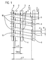
Aus Figur 1 ist die Erfindung ersichtlich, wobei die Beschreibung im Anschluß an die Beschreibung der Figur 2 erfolgt, die den Stand der Technik in Form einer Winkelmeßeinrichtung zeigt. Derartige Winkelmeßeinrichtungen - auch als inkrementale Drehgeber bezeichnet - arbeiten nach dem Prinzip der photoelektrischen Abtastung feiner Gitter.The invention can be seen from FIG. 1, the description following the description of FIG. 2, which shows the prior art in the form of an angle measuring device. Such angle measuring devices - also called incremental rotary encoders - work on the principle of photoelectric scanning of fine gratings.
Inkrementale Drehgeber 1 besitzen als Maßverkörperung eine Teilscheibe 2 aus Glas mit einem Radialgitter 3 aus Strichen und Lücken. Die lichtundurchlässigen Striche, die etwa so breit sind wie die lichtdurchlässigen Lücken, bestehen aus Chrom, das auf den Glaskörper 2 aufgedampft wird. Auf einer zweiten Spur befindet sich zusätzlich eine Referenzmarke 4.Incremental
In geringem Abstand gegenüber der drehbaren, auf einer Welle 5 befestigten Teilscheibe 2 ist eine Abtasteinheit 8 angeordnet, die auf vier Feldern 10 jeweils die gleiche Gitterteilung 3 wie die Teilscheibe 2 und ein Abtastfeld 11 für die Referenzmarke 4 trägt. Die vier Strichgitter der Abtastplatte 8 sind jeweils um ein Viertel der Teilungsperiode - d.h. ein Viertel des Abstandes zwischen zwei Strichen - zueinander versetzt.A
Alle Felder werden von einem parallel ausgerichteten Lichtbündel durchstrahlt, das von einer LED 6 oder einer Miniaturlampe mit Kondensor 7 ausgeht. Bei einer Drehung der Teilscheibe 2 wird der Lichtstrom moduliert und seine Intensität von Silizium-Photoelementen 9 erfaßt. Die Photoelemente 9 sind so geschaltet, daß sie zwei elektrisch annähernd sinusförmige Signale und eine von der Referenzmarke 4 abgeleitete Signalspitze - nämlich das Referenzmarkensignal liefern.A parallel beam of light shines through all fields, which emanates from an
Anhand eines schematisch dargestellten Ausschnittes soll nun die Erfindung mit Hilfe der Figur 1 erläutert werden. Von einer nichtdargestellten Lichtquelle wird kollimiertes Licht schräg zu den Teilungsebenen des Maßstab- 3, 4 und des Abtastgitters 10, 11 auf Detektoren 9 geleitet.The invention will now be explained with the aid of FIG. 1 on the basis of a schematically illustrated section. Collimated light is directed obliquely from a light source, not shown, to the division planes of the
Die Teilungsebenen sind die Ebenen, in denen sich die Teilungsstriche des Maßstabgitters 3, 4 und des Abtastgitters 10, 11 befinden. Die Teilungsstriche verlaufen parallel zur Zeichnungsebene von oben nach unten. Wesentlich ist dabei, daß außer dem Merkmal des schräg auf die Teilungsebenen des Maßstabgitters 3, 4 und des Abtastgitters 10, 11 auftreffendes Lichtes dieses Licht parallel zur Ausrichtung der Gitterstriche verläuft. Dadurch ist gewährleistet, daß die Phasenverhältnisse konstant bleiben. Zudem ist von entscheidender Bedeutung, daß die Länge der Gitterteilungsstriche sowohl der Gitter des Maßstabes als auch der der Abtasteinheit begrenzt wird.The graduation planes are the planes in which the graduation marks of the scale grating 3, 4 and the scanning grating 10, 11 are located. The division lines run parallel to the drawing plane from top to bottom. It is essential that in addition to the feature of the light incident obliquely on the division planes of the scale grating 3, 4 and the scanning grating 10, 11, this light runs parallel to the alignment of the grating lines. This is ensures that the phase relationships remain constant. It is also of crucial importance that the length of the grating graduation lines is limited, both the grating of the scale and that of the scanning unit.
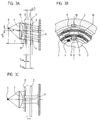
Dies wird deutlich, wenn die Figuren 3 bis 5 betrachtet werden. Aus Figur 3A ist ersichtlich, daß sich die Gitterstriche über Teilbereiche der Teilungsebene erstrecken. Deutlicher wird dies in der Teilansicht gemäß Figur 3B. Dort werden die Teilungsspuren 3 durch Spuren radial begrenzt, die keine Teilung tragen und wie eine Maske wirken. Diese Bereiche sind punktiert dargestellt. Figur 3C zeigt lediglich eine weitere Ansicht, aber die Figuren 3A und 3B zeigen die Erfindung deutlicher.This becomes clear when looking at Figures 3 to 5. It can be seen from FIG. 3A that the grating lines extend over partial regions of the division plane. This becomes clearer in the partial view according to FIG. 3B. There, the
In Figur 3A ist die Teilscheibe 2 in zwei verschiedenen Stellungen dargestellt, die sich um den Abstand ΔS unterscheiden. Mit durchgezogenen Linien ist die Stellung mit dem maximalen Abtastabstand Smax von dem Abtastgitter 8 gezeigt und mit punktierten Konturen der minimale Abtastabstand Smin. Beim maximalen Abtastabstand Smax werden die Detektoren 9 maximal ausgeleuchtet. Beim minimalen Abtastabstand Smin wird ein Teil der Beleuchtungsstrahlen durch die vorerwähnten Masken abgeschattet, so daß die Detektoren 9 weniger Licht empfangen, womit die höhere Intensität, die durch die Annäherung an die Beleuchtung 6, 7 auftritt, kompensiert wird.In FIG. 3A, the graduated
Der optische Aufbau ist dabei folgender: Figur 3A zeigt die Beleuchtungsanordnung 6, 7, bei der die Lichtquelle (LED od. Lampe) 6 in der Brennebene, in Strichrichtung um ΔXL verschoben zur optischen Achse angeordnet ist. Dadurch ergibt sich ein paralleler Strahlengang der zur optischen Achse, in Strichrichtung um den Winkel
geneigt ist.The optical structure is as follows: FIG. 3A shows the
is inclined.
Die Abtastfelder 10, 11 können je nach Bedarf nebeneinander, untereinander oder kreuzweise angeordnet werden. Wobei die Abtastfelder 10, 11 im Verhältnis 1:1 oder nach ArcSin geteilt sein können. D.h. die Gitterstriche können genauso breit sein, wie die Lücken oder nach einer bestimmten Funktion ausgebildet sein.The scanning fields 10, 11 can be arranged side by side, one below the other or crosswise as required. The scanning fields 10, 11 can be divided in a ratio of 1: 1 or according to ArcSin. I.e. the grid lines can be as wide as the gaps or can be designed according to a specific function.
Die Strichlängen auf der Maßstabsteilung entsprechen der Strichlänge der Abtastfelder und sind um den Betrag
zur Strichplatte versetzt.The line lengths on the scale division correspond to the line length of the scanning fields and are by the amount
offset to the graticule.
Die Striche 3 der Maßverkörperung 2 sind durch lichtundurchlässige Stege getrennt, die die bereits beschriebenen Masken bilden.The
Die Detektoren 9 sind ebenfalls ums den Betrag
in gleicher Richtung versetzt angeordnet.The
offset in the same direction.
Bei der beschriebenen Anordnung ergibt sich bei dem Abstand Smax die maximale Beleuchtung der Detektoren 9.In the arrangement described, the maximum illumination of the
Bei Abstandsverminderung wird nun der Vergrößerung des Abtastsignales durch Abschattung des Lichtstromes entgegengewirkt.If the distance is reduced, the magnification of the scanning signal is counteracted by shadowing the luminous flux.
Kennt man die, für jede Teilungsperiode bei herkömmlicher Beleuchtung zu ermittelnde Signaländerung in Abhängigkeit vom Arbeitsabstand, d.h., die maximale Intensität Imax bei minimalem Abstand Smin und die minimale Intensität Imin bei maximalem Abstand Smax, so läßt sich die Ablage der Lichtquelle ΔXL bei gegebenen geometrischen und optischen Daten wie folgt ermitteln:
Durch Einsetzen und Umformen ergibt sich:
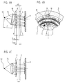
Ebenso ist es denkbar, eine schräge Beleuchtung durch Schrägstellung der gesamten Beleuchtungseinheit - Lampe 6 und Kondensor 7 - zu erzeugen, was in Figur 4A und 4C dargestellt ist.Knowing the signal change to be determined for each division period with conventional lighting as a function of the working distance, i.e. the maximum intensity Imax at a minimum distance Smin and the minimum intensity Imin at a maximum distance Smax, it is possible to store the light source ΔX L at given geometric distances and optical data as follows:
Inserting and reshaping results in:
It is also conceivable to generate oblique lighting by inclining the entire lighting unit -
Da dort im übrigen die gleichen Verhältnisse vorliegen, wie bei der Ausführungsform gemäß Figur 3A bis 3C wurden dieselben Bezugszeichen auch für die Figur 4A bis 4C eingesetzt.Since the conditions are the same as in the embodiment according to FIGS. 3A to 3C, the same reference numerals have also been used for FIGS. 4A to 4C.
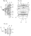
Abweichend von den vorstehenden Ausführungsbeispielen, die mit kollimiertem, schräg auf die Teilungsebenen fallendem Licht arbeiten, zeigt das Ausführungsbeispiel gemäß Figur 5A bis 5C eine Lösung, die mit divergierendem Licht - aber nur in einer Ebene - arbeitet. In Strichrichtung, also in Richtung des Verlaufes der Gitterstriche ist der Beleuchtungsstrahlengang parallel ausgerichtet.Deviating from the above exemplary embodiments, which work with collimated light falling obliquely onto the parting planes, the exemplary embodiment according to FIGS. 5A to 5C shows a solution which works with divergent light - but only in one plane. The illuminating beam path is aligned parallel in the direction of the line, ie in the direction of the course of the grating lines.
Der optische Aufbau ist aus Figur 5A bis 5B ersichtlich.The optical structure can be seen from FIGS. 5A to 5B.
Eine Zylinderlinse 75 erzeugt von einer Lichtquelle 65, die sich im Brennpunkt befindet, nur in einer Ebene ein paralleles Strahlenbündel, während in der anderen Ebene die Fotoelemente 95 durch Strahlenbündel, die einen bestimmten Winkel zur optischen Achse haben, ausgeleuchtet werden. Diese Teilstrahlenbündel werden durch Masken auf der Teilscheibe 25 so begrenzt, daß bei größtem Abstand die Fotoelemente 95 maximal ausgeleuchtet werden.A
Verringert nun die Teilscheibe 25 den Abstand zum Abtastgitter 85, so werden von den Teilstrahlenbündeln entsprechende Flächen durch die auf der Teilscheibe 25 befindlichen Masken abgeblendet, so daß eine Amplitudenvergrößerung kompensiert wird.If the
Unterschiedliche Gitterkonstanten erfordern entsprechende Abblendungen. Ein Maß für die Abblendung in Abhängigkeit von der Abstandsänderung ist der Winkel (α, β) den die Strahlenbündel zur optischen Achse bilden. Dadurch ist es möglich, bei einem Abtastkopf unterschiedliche Gitterkonstanten zu kompensieren (Referenzmarke!).Different lattice constants require corresponding dimming. A measure of the dimming as a function of the change in distance is the angle (α, β) that the beams form to the optical axis. This makes it possible to compensate for different grating constants in a scanning head (reference mark!).
Claims (6)
Priority Applications (7)
| Application Number | Priority Date | Filing Date | Title |
|---|---|---|---|
| DE59307609T DE59307609D1 (en) | 1993-07-17 | 1993-07-17 | Length or angle measuring device |
| EP93111500A EP0635701B1 (en) | 1993-07-17 | 1993-07-17 | Length or angle measuring device |
| AT93111500T ATE159811T1 (en) | 1993-07-17 | 1993-07-17 | LENGTH OR ANGLE MEASURING DEVICE |
| JP6145026A JP2705712B2 (en) | 1993-07-17 | 1994-06-27 | Length measuring or angle measuring device |
| DE4423877A DE4423877A1 (en) | 1993-07-17 | 1994-07-07 | Length or angle measuring device |
| DE9422212U DE9422212U1 (en) | 1993-07-17 | 1994-07-07 | Length or angle measuring device |
| US08/275,975 US5493399A (en) | 1993-07-17 | 1994-07-15 | Position measuring system with compensation for variable distance between light source and index disk |
Applications Claiming Priority (1)
| Application Number | Priority Date | Filing Date | Title |
|---|---|---|---|
| EP93111500A EP0635701B1 (en) | 1993-07-17 | 1993-07-17 | Length or angle measuring device |
Publications (2)
| Publication Number | Publication Date |
|---|---|
| EP0635701A1 true EP0635701A1 (en) | 1995-01-25 |
| EP0635701B1 EP0635701B1 (en) | 1997-10-29 |
Family
ID=8213088
Family Applications (1)
| Application Number | Title | Priority Date | Filing Date |
|---|---|---|---|
| EP93111500A Expired - Lifetime EP0635701B1 (en) | 1993-07-17 | 1993-07-17 | Length or angle measuring device |
Country Status (5)
| Country | Link |
|---|---|
| US (1) | US5493399A (en) |
| EP (1) | EP0635701B1 (en) |
| JP (1) | JP2705712B2 (en) |
| AT (1) | ATE159811T1 (en) |
| DE (2) | DE59307609D1 (en) |
Cited By (1)
| Publication number | Priority date | Publication date | Assignee | Title |
|---|---|---|---|---|
| DE19726935B4 (en) * | 1997-06-25 | 2014-06-12 | Dr. Johannes Heidenhain Gmbh | Optical position measuring device |
Families Citing this family (6)
| Publication number | Priority date | Publication date | Assignee | Title |
|---|---|---|---|---|
| DE59912617D1 (en) | 1998-08-01 | 2006-02-16 | Heidenhain Gmbh Dr Johannes | Rotary position measuring device |
| EP1028309B1 (en) | 1999-02-04 | 2003-04-16 | Dr. Johannes Heidenhain GmbH | Optical encoder |
| US7032188B2 (en) * | 2001-09-28 | 2006-04-18 | Nokia Corporation | Multilevel sorting and displaying of contextual objects |
| DE10333772A1 (en) * | 2002-08-07 | 2004-02-26 | Dr. Johannes Heidenhain Gmbh | Interference-based position measurement instrument detects the relative movement of measurement and scanning gratings in that a periodic interference band pattern is generated from which phase shifts and positions are measured |
| US7102123B2 (en) * | 2003-10-28 | 2006-09-05 | Avago Technologies Ecbu Ip (Singapore) Pte. Ltd. | Reflective imaging encoder |
| DE102005036161A1 (en) * | 2005-08-02 | 2007-02-08 | Dr. Johannes Heidenhain Gmbh | Field modulating angle measuring device and method for its operation |
Citations (3)
| Publication number | Priority date | Publication date | Assignee | Title |
|---|---|---|---|---|
| DE2510273A1 (en) * | 1975-03-08 | 1976-09-16 | Heidenhain Gmbh Dr Johannes | PHOTOELECTRIC MEASURING EQUIPMENT |
| EP0418211A2 (en) * | 1989-09-12 | 1991-03-20 | Heinz Rieder | Incremental measuring system |
| GB2246431A (en) * | 1988-01-22 | 1992-01-29 | Mitutoyo Corp | Optical encoder |
Family Cites Families (8)
| Publication number | Priority date | Publication date | Assignee | Title |
|---|---|---|---|---|
| US3400275A (en) * | 1965-07-22 | 1968-09-03 | Trump Ross Ind Controls Inc | Optical encoder having a common light source located in a rotatable shuttered housing |
| CA1060585A (en) * | 1974-03-28 | 1979-08-14 | Marc Lepetit | Digital coding of angles |
| US4266125A (en) * | 1978-12-21 | 1981-05-05 | Hewlett-Packard Company | Optical shaft angle encoder |
| US4263506A (en) * | 1978-12-21 | 1981-04-21 | Hewlett-Packard Company | Pulse generating apparatus |
| DE2900295C2 (en) * | 1979-01-05 | 1982-06-24 | Philips Patentverwaltung Gmbh, 2000 Hamburg | Photoelectric pulse generator |
| JPS62278408A (en) * | 1986-05-28 | 1987-12-03 | Tamagawa Seiki Co Ltd | Analog chopping wave output encoder |
| JPH02126114A (en) * | 1988-11-04 | 1990-05-15 | Smc Corp | Encoder |
| JP3067282B2 (en) * | 1991-06-13 | 2000-07-17 | 株式会社東海理化電機製作所 | Movement detector |
-
1993
- 1993-07-17 EP EP93111500A patent/EP0635701B1/en not_active Expired - Lifetime
- 1993-07-17 DE DE59307609T patent/DE59307609D1/en not_active Expired - Fee Related
- 1993-07-17 AT AT93111500T patent/ATE159811T1/en not_active IP Right Cessation
-
1994
- 1994-06-27 JP JP6145026A patent/JP2705712B2/en not_active Expired - Fee Related
- 1994-07-07 DE DE4423877A patent/DE4423877A1/en not_active Withdrawn
- 1994-07-15 US US08/275,975 patent/US5493399A/en not_active Expired - Fee Related
Patent Citations (3)
| Publication number | Priority date | Publication date | Assignee | Title |
|---|---|---|---|---|
| DE2510273A1 (en) * | 1975-03-08 | 1976-09-16 | Heidenhain Gmbh Dr Johannes | PHOTOELECTRIC MEASURING EQUIPMENT |
| GB2246431A (en) * | 1988-01-22 | 1992-01-29 | Mitutoyo Corp | Optical encoder |
| EP0418211A2 (en) * | 1989-09-12 | 1991-03-20 | Heinz Rieder | Incremental measuring system |
Cited By (1)
| Publication number | Priority date | Publication date | Assignee | Title |
|---|---|---|---|---|
| DE19726935B4 (en) * | 1997-06-25 | 2014-06-12 | Dr. Johannes Heidenhain Gmbh | Optical position measuring device |
Also Published As
| Publication number | Publication date |
|---|---|
| DE4423877A1 (en) | 1995-01-19 |
| DE59307609D1 (en) | 1997-12-04 |
| EP0635701B1 (en) | 1997-10-29 |
| JPH07151566A (en) | 1995-06-16 |
| JP2705712B2 (en) | 1998-01-28 |
| US5493399A (en) | 1996-02-20 |
| ATE159811T1 (en) | 1997-11-15 |
Similar Documents
| Publication | Publication Date | Title |
|---|---|---|
| EP0160811B1 (en) | Photoelectric measuring device | |
| EP0513427B1 (en) | Interferometric position measuring device | |
| DE10037979B4 (en) | Optical encoder | |
| EP1407231B1 (en) | Position measuring device | |
| EP2520906B1 (en) | Optical positioning device | |
| EP2063230B1 (en) | Optical positioning device | |
| DE4226683B9 (en) | Optical motion sensor | |
| EP0163824A2 (en) | Photoelectric measuring device | |
| EP0083689B1 (en) | Photoelectric incremental length or angle measuring device | |
| DE112011104918T5 (en) | Optical encoder | |
| EP0493385A1 (en) | High-resolution coder. | |
| EP2404143A2 (en) | Position measuring device | |
| EP0363620A1 (en) | Photoelectrical position-measuring device | |
| EP0635701B1 (en) | Length or angle measuring device | |
| DE10058239A1 (en) | A position | |
| EP0754933B1 (en) | Position measuring device | |
| EP0237835B1 (en) | Measuring device | |
| DE102014215633A1 (en) | Position measuring device | |
| EP0547270B1 (en) | Fotoelectric apparatus for the generation of harmonic-free periodic signals | |
| DE10346380B4 (en) | Position measuring device | |
| EP0498904B1 (en) | Photo-electric position measuring device | |
| DE19518714A1 (en) | Optical sensor with measuring body | |
| DE4303161C2 (en) | Photoelectric length or angle measuring system with a device for detecting guide errors | |
| DE19922009B4 (en) | Rotary position measuring device | |
| DE202005002622U1 (en) | Optical position sensor has reference scale with zones of different reflectivity and sensor plate of different transmission to generate reference pulse |
Legal Events
| Date | Code | Title | Description |
|---|---|---|---|
| PUAI | Public reference made under article 153(3) epc to a published international application that has entered the european phase |
Free format text: ORIGINAL CODE: 0009012 |
|
| 17P | Request for examination filed |
Effective date: 19930805 |
|
| AK | Designated contracting states |
Kind code of ref document: A1 Designated state(s): AT DE FR GB IT |
|
| 17Q | First examination report despatched |
Effective date: 19950614 |
|
| GRAG | Despatch of communication of intention to grant |
Free format text: ORIGINAL CODE: EPIDOS AGRA |
|
| GRAH | Despatch of communication of intention to grant a patent |
Free format text: ORIGINAL CODE: EPIDOS IGRA |
|
| GRAH | Despatch of communication of intention to grant a patent |
Free format text: ORIGINAL CODE: EPIDOS IGRA |
|
| ITF | It: translation for a ep patent filed |
Owner name: DE DOMINICIS & MAYER S.R.L. |
|
| GRAA | (expected) grant |
Free format text: ORIGINAL CODE: 0009210 |
|
| AK | Designated contracting states |
Kind code of ref document: B1 Designated state(s): AT DE FR GB IT |
|
| REF | Corresponds to: |
Ref document number: 159811 Country of ref document: AT Date of ref document: 19971115 Kind code of ref document: T |
|
| ET | Fr: translation filed | ||
| GBT | Gb: translation of ep patent filed (gb section 77(6)(a)/1977) |
Effective date: 19971031 |
|
| REF | Corresponds to: |
Ref document number: 59307609 Country of ref document: DE Date of ref document: 19971204 |
|
| PLBE | No opposition filed within time limit |
Free format text: ORIGINAL CODE: 0009261 |
|
| STAA | Information on the status of an ep patent application or granted ep patent |
Free format text: STATUS: NO OPPOSITION FILED WITHIN TIME LIMIT |
|
| 26N | No opposition filed | ||
| REG | Reference to a national code |
Ref country code: GB Ref legal event code: IF02 |
|
| PGFP | Annual fee paid to national office [announced via postgrant information from national office to epo] |
Ref country code: GB Payment date: 20040630 Year of fee payment: 12 |
|
| PGFP | Annual fee paid to national office [announced via postgrant information from national office to epo] |
Ref country code: AT Payment date: 20040705 Year of fee payment: 12 |
|
| PGFP | Annual fee paid to national office [announced via postgrant information from national office to epo] |
Ref country code: FR Payment date: 20040708 Year of fee payment: 12 |
|
| PG25 | Lapsed in a contracting state [announced via postgrant information from national office to epo] |
Ref country code: IT Free format text: LAPSE BECAUSE OF NON-PAYMENT OF DUE FEES Effective date: 20050717 Ref country code: AT Free format text: LAPSE BECAUSE OF NON-PAYMENT OF DUE FEES Effective date: 20050717 |
|
| GBPC | Gb: european patent ceased through non-payment of renewal fee |
Effective date: 20050717 |
|
| PG25 | Lapsed in a contracting state [announced via postgrant information from national office to epo] |
Ref country code: FR Free format text: LAPSE BECAUSE OF NON-PAYMENT OF DUE FEES Effective date: 20060331 |
|
| REG | Reference to a national code |
Ref country code: FR Ref legal event code: ST Effective date: 20060331 |
|
| PGFP | Annual fee paid to national office [announced via postgrant information from national office to epo] |
Ref country code: DE Payment date: 20080722 Year of fee payment: 16 |
|
| PG25 | Lapsed in a contracting state [announced via postgrant information from national office to epo] |
Ref country code: DE Free format text: LAPSE BECAUSE OF NON-PAYMENT OF DUE FEES Effective date: 20100202 |