EP0634876A1 - Device for transmitting a digital picture signal - Google Patents
Device for transmitting a digital picture signal Download PDFInfo
- Publication number
- EP0634876A1 EP0634876A1 EP94201972A EP94201972A EP0634876A1 EP 0634876 A1 EP0634876 A1 EP 0634876A1 EP 94201972 A EP94201972 A EP 94201972A EP 94201972 A EP94201972 A EP 94201972A EP 0634876 A1 EP0634876 A1 EP 0634876A1
- Authority
- EP
- European Patent Office
- Prior art keywords
- picture
- sub
- hdtv
- signal
- sdtv
- Prior art date
- Legal status (The legal status is an assumption and is not a legal conclusion. Google has not performed a legal analysis and makes no representation as to the accuracy of the status listed.)
- Granted
Links
Images
Classifications
-
- H—ELECTRICITY
- H04—ELECTRIC COMMUNICATION TECHNIQUE
- H04N—PICTORIAL COMMUNICATION, e.g. TELEVISION
- H04N5/00—Details of television systems
- H04N5/44—Receiver circuitry for the reception of television signals according to analogue transmission standards
- H04N5/445—Receiver circuitry for the reception of television signals according to analogue transmission standards for displaying additional information
- H04N5/45—Picture in picture, e.g. displaying simultaneously another television channel in a region of the screen
-
- G—PHYSICS
- G11—INFORMATION STORAGE
- G11B—INFORMATION STORAGE BASED ON RELATIVE MOVEMENT BETWEEN RECORD CARRIER AND TRANSDUCER
- G11B27/00—Editing; Indexing; Addressing; Timing or synchronising; Monitoring; Measuring tape travel
- G11B27/02—Editing, e.g. varying the order of information signals recorded on, or reproduced from, record carriers
- G11B27/031—Electronic editing of digitised analogue information signals, e.g. audio or video signals
- G11B27/032—Electronic editing of digitised analogue information signals, e.g. audio or video signals on tapes
-
- H—ELECTRICITY
- H04—ELECTRIC COMMUNICATION TECHNIQUE
- H04N—PICTORIAL COMMUNICATION, e.g. TELEVISION
- H04N9/00—Details of colour television systems
- H04N9/79—Processing of colour television signals in connection with recording
- H04N9/7921—Processing of colour television signals in connection with recording for more than one processing mode
- H04N9/7925—Processing of colour television signals in connection with recording for more than one processing mode for more than one standard
-
- H—ELECTRICITY
- H04—ELECTRIC COMMUNICATION TECHNIQUE
- H04N—PICTORIAL COMMUNICATION, e.g. TELEVISION
- H04N9/00—Details of colour television systems
- H04N9/79—Processing of colour television signals in connection with recording
- H04N9/80—Transformation of the television signal for recording, e.g. modulation, frequency changing; Inverse transformation for playback
- H04N9/804—Transformation of the television signal for recording, e.g. modulation, frequency changing; Inverse transformation for playback involving pulse code modulation of the colour picture signal components
- H04N9/8042—Transformation of the television signal for recording, e.g. modulation, frequency changing; Inverse transformation for playback involving pulse code modulation of the colour picture signal components involving data reduction
- H04N9/8047—Transformation of the television signal for recording, e.g. modulation, frequency changing; Inverse transformation for playback involving pulse code modulation of the colour picture signal components involving data reduction using transform coding
-
- G—PHYSICS
- G11—INFORMATION STORAGE
- G11B—INFORMATION STORAGE BASED ON RELATIVE MOVEMENT BETWEEN RECORD CARRIER AND TRANSDUCER
- G11B2220/00—Record carriers by type
- G11B2220/90—Tape-like record carriers
Definitions
- the invention relates to a device for transmitting a digital picture signal. More particularly, the invention relates to a device provided with encoding means for forming a mean value and a series of other data words of successive picture blocks of the picture signal. Transmission of picture signals is also understood to mean recording and reproducing the signals. The invention also relates to a device for receiving a digital picture signal.
- HDTV high-definition
- Such devices will in due course provide the possibility of realising HDTV video recorders having technically and economically feasible specifications as regards their electrical and mechanical aspects and as regards the use of tapes.
- Video recorders for recording, editing and display of digital picture signals having a lower standard definition (SDTV) are, however, already produced in large quantities.
- SDTV standard definition
- professional PCM video recorders which can record and play back an uncompressed digital SDTV picture signal are still available in large quantities and to an increasing extent. Also in the future, they will be considerably cheaper than HDTV recorders for a long time.
- HDTV picture signals It is possible to compress HDTV picture signals to a bit rate which corresponds to that of an uncompressed SDTV picture signal.
- the compressed HDTV signal can then be transmitted via available SDTV channels and registered on the known PCM recorders.
- compression and decompression units integrated or not integrated in recorders
- HDTV monitors are required for editing HDTV programs. This involves a costly investment in appropriate HDTV equipment.
- the device is characterized in that it comprises formatting means for accommodating the mean value of successive picture blocks of each picture at those positions of the channel bit stream which form a sub-picture in a picture signal of lower definition.
- European Patent Application EP 0 272 762 discloses a device for splitting HDTV picture signals into two bit streams, one bit stream of which represents a compatible SDTV picture signal and the other bit stream comprises supplementary data for the full reconstruction of the HDTV picture signal.
- the SDTV picture signal may be displayed with the lower definition on the full screen of standard television receivers.
- recording, editing and display of the HDTV picture signals still requires special HDTV video recorders which are adapted to process both bit streams.
- a corresponding device for receiving a compressed high-definition digital picture signal is characterized in that it comprises deformatting means for splitting the channel bit stream into the mean values and the other data words.
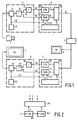
- Fig. 1 shows a transmission system comprising a device for transmitting and a device for receiving high-definition picture signals according to the invention.
- Fig. 2 shows the structure of a control unit shown in Fig. 1.
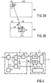
- Fig. 3 shows the structure of a HDTV picture and a corresponding SDTV picture for explaining the operation of a formatting unit shown in Fig. 1.
- Fig. 4 shows a further embodiment of the device for transmitting a picture signal.
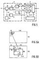
- Fig. 5 shows a further embodiment of the device for receiving a picture signal.
- Fig. 6 shows the structure of a HDTV picture and a corresponding SDTV picture for explaining the operation of the embodiments shown in Figs. 4 and 5.
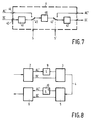
- Fig. 7 shows an example of the use of an alternative embodiment of a video recorder in the transmission system shown in Fig. 1.
- Fig. 8 shows a transmission system provided with a scrambler and a descrambler.
- Fig. 1 shows a transmission system for high-definition picture signals.
- the system comprises successively a HDTV picture source 1, an encoding unit 2, a formatting unit 3, a digital video recorder 4, a deformatting unit 5, a decoding unit 6 and a HDTV receiver 7.
- the encoding unit 2 and the formatting unit 3 constitute the device for transmitting picture signals according to the invention.
- the deformatting unit 5 and the decoding unit 6 constitute the device for receiving the picture signals according to the invention.
- the transmitted digital picture signals are also applied to a standard television receiver 8 via a D/A converter (not shown).
- Picture source 1 for example a HDTV camera, generates a picture signal at a high definition of, for example 1440 pixels per line and 1152 lines.
- This picture signal is applied to the encoding unit 2 which is known per se and will only be described as far as this important for a satisfactory understanding of the invention.
- the encoding unit comprises a picture memory 21 by means of which the HDTV picture is divided into picture blocks of, for example 8*8 pixels. These picture blocks have a block address (i, j) which is generated by an addressing circuit 22.
- Each picture block is subjected in a transformer 23 to an orthogonal picture transform, for example Discrete Cosine Transform (DCT).
- DCT Discrete Cosine Transform
- coefficients one represents the mean value of the picture block. This coefficient will hereinafter be referred to as the DC value of the picture block.
- the other coefficients are AC coefficients. These coefficients are applied to a quantizing and coding circuit 24 in which they are subjected to, for example variable-length coding.
- the code words thus obtained, which are representative of the AC coefficients of a picture block, are denoted by AC' in the Figure.
- the encoding is realised separately for the luminance signal Y and the chrominance signals U and V.
- the chrominance signals are often sampled at a lower sample frequency so that one picture block U and one picture block V are present for two consecutive picture blocks Y. They are transformed and coded in the sequence YUYV.
- the quantity of data for each compressed HDTV picture is then equal to that of an uncompressed SDTV picture which, as is known, comprises 720 pixels per line and 576 lines.
- Digital video recorders for recording such uncompressed SDTV picture signals are known. They are described, for example in "Standard for recording digital television signals on magnetic tape in cassettes", EBU-Tech. 3252-E, September 1986. As described in this article, 8-bit data words are applied to this video recorder in the sequence YUYV in which Y represents the luminance of a pixel and U and V represent the chrominance of a pair of pixels.
- the video recorder 4 shown in the Figure is preferably such a video recorder.
- the HDTV picture signal compressed by the encoding unit 2 and comprising the DC value as well as the code words AC' of each picture block is applied to the formatting unit 3.
- This unit comprises a first memory 31 to which the DC values are applied, a second memory 32 to which the code words AC' are applied, a multiplexer 33 and a control circuit 34.
- the formatting unit receives the block coordinates (i, j) of the current picture block.
- the first memory 31 is a RAM and the second memory 32 is a FIFO. If desired, the second memory 32 may also be of the RAM type. In that case both memories may be implemented as one integrated memory and the multiplexer is superfluous.
- the operation of the formatting unit will now be explained as regards the luminance information Y.
- the chrominance signals U and V are processed identically.
- the DC value of each picture block Y is stored in the RAM 31, which receives the block coordinates (i, j) as a write address from addressing circuit 22.
- the other code words AC' of the picture block are written at successive locations of FIFO 32.
- the memories are read under the control of control circuit 34. In practice, the memories may have a double implementation in order that reading of a picture coincides with storage of the next picture.
- the control circuit is further shown in Fig. 2.
- a 720-divider 341 which receives clock pulses at a frequency of 13.5 MHz, followed by a 576-divider 342.
- the 720-divider generates a column number c
- the 576-divider generates a row number r.
- These numbers are applied to a decoder 343 which constitutes a read address (x, y) and a selection signal S from c and r.
- S 0 for 270 ⁇ c ⁇ 450 and 216 ⁇ r ⁇ 360
- the two memories are thus read in the form of 576 series of 720 8-bit words each, analogously to the 576 picture lines of 720 pixels each of an imaginary SDTV picture signal in PCM format.
- the DC value of pixel block (i, j) stored in RAM address (i, j) corresponds to pixel (270+i, 216+j) of the imaginary SDTV signal.
- the 180*144 DC values of the original HDTV signal (Fig. 3A) thus constitute, as it were, a sub-picture in an imaginary SDTV picture (Fig. 3B). Said sub-picture has a dimension of 180*144 pixels and an arbitrarily adjustable origin (here (270, 216)).
- the DC values of luminance and chrominance blocks are grouped in the sequence YUYV.
- the output signal thus obtained is applied to SDTV recorder 4 and/or SDTV receiver 8 (see Fig. 1). Both apparatuses interpret consecutive 8-bit words as consecutive PCM pixels of an uncompressed SDTV picture signal. In this way, the transmitted signal can be recorded, played back and displayed as a genuine SDTV signal. Since each pixel in the sub-picture represents the mean value of a corresponding 8*8 HDTV picture block, the sub-picture constitutes a smaller, but recognizable and acceptable version of the full HDTV picture. The aspect ratio of the sub-picture (4:3) differs from that of the HDTV picture (16:9), but this is no drawback for recognizing the picture.
- the pixels outside the sub-picture are successive 8-bit samples of a bit stream of variable-length code words. In SDTV display, they appear to form a kind of noise which is not troublesome for the perception of the sub-picture.
- the compressed HDTV picture signals can thus be recorded and played back with standard recorders, and judged with standard receivers. Editing is no problem and is possible without having to use any further additional facilities. As far as video recorders are equipped with facilities such as stills, fast search and the like, they also apply to the HDTV sub-pictures. Experiments have proved that even 40 times faster display still yields a recognizable sub-picture.
- an edited HDTV television program is of course displayed again on a HDTV receiver.
- the deformatting unit comprises a demultiplexer 53, a first (RAM) memory 51, a second (FIFO) memory 52 and a control circuit 54. All these elements have the same structure as the corresponding elements of the formatting unit 3 already described. A more detailed explanation of the operation is therefore unnecessary.
- the selection signal applied to demultiplexer 53 is now denoted by S' and that the address (x, y) applied to the RAM 51 is now a write address.
- the decoding unit 6 comprises an addressing circuit 62 which generates successive read addresses (i, j) for reading the DC values of each picture block stored in RAM 51. Moreover, the decoding unit receives, from each picture block, the code words AC' which are representative of the AC coefficients. The code words AC' are applied to a decoding circuit 64 with which the original AC coefficients are regained. An inverse picture transformer 63 transforms the coefficients of a picture block back to the pixel domain and stores the pixels thus obtained in a picture memory 61 under the control of block coordinates (i, j). The 1440*1152 pixels of the HDTV picture are regained in this further known manner.
- Fig. 4 shows a further embodiment of the device for transmitting the picture signal. Elements in this Figure having the same function as those in Fig. 1 are denoted by the same reference numerals.
- the device shown in Fig. 4 now comprises an address converter 25 which successively generates four write addresses (2i, 2j), (2i, 2j+1), (2i+1, 2j) and (2i+1, 2j+1) for the RAM 31 for each block coordinate (i, j). In this way, the DC value of each 8*8 picture block is written four times into RAM 31.
- the corresponding SDTV sub-picture now comprises 360*288 pixels. In other words, it is twice as large in the horizontal and vertical directions as the sub-picture shown in Fig. 3.
- the SDTV sub-picture can thus be better recognized but it does not have an enhanced resolution.
- Fig. 5 shows the corresponding device for receiving the picture signals.
- This device comprises an address converter 65 which causes one of the RAM locations (2i, 2j), (2i, 2j+1), (2i+1, 2j) or (2i+1, 2j+1) to be read for block coordinate (i, j).
- the actually read location is not important because the same DC value is stored at all four locations.
- the resolution of the larger sub-picture thus obtained can be enhanced by not duplicating the one DC value but by generating four distinct DC values for each 8*8 picture block.
- This is shown in Fig. 4 by means of a broken line DC producer 26. It divides each applied picture block of 8*8 pixels into four sub-blocks of 4*4 pixels and computes the average luminance and chrominance values for each sub-block.
- the four DC values are stored at the afore-mentioned RAM locations (2i, 2j), (2i, 2j+1), (2i+1, 2j) and (2i+1, 2j+1).
- the resolution of the sub-picture shown in Fig. 6B is now doubled in both the horizontal and the vertical direction.
- the corresponding device for receiving the picture signal now comprises a DC averager 66 (shown in broken lines in Fig. 5). This averager receives the four DC values and averages them so that the mean value of the 8*8 picture block is regained again. The value obtained is applied as a DC coefficient to the inverse picture transformer 63.
- the sub-picture can be magnified in only one (horizontal or vertical) direction. This option is sensible when the compressed HDTV picture signal only provides space for accommodating, per picture block, two DC values in the channel bit stream. It is true that the aspect ratio of the sub-picture is then affected but the sub-picture can still be recognized. It is also possible to form the distinct DC values from the DC coefficient of a transformed picture block and the three AC coefficients of the lowest order.
- Fig. 7 shows a video recorder 4 which itself is provided with a compression unit 41 and a decompression unit 42.
- a digital input 43 for receiving digital SDTV signals (for example in the YUYV format already referred to).
- the sub-picture is compressed and upon display it is decompressed.
- the code words AC' are presented to a further input 44 and directly stored on tape 46 via a switch 45.
- the switch 45 is controlled by the selection signal S of the formatting unit 3 (Fig. 1).
- the reason behind this is that the usual compression methods are only effective if they are used for genuine television pictures in which there is a correlation between contiguous pixels. This is the case for the sub-picture. However, the compression would be unsuitable for the code words AC' because the required correlation between consecutive 8-bit words is absent.
- the recorder 4 now functions, as it were, as a video recorder during the sub-picture and as a data recorder outside this picture, so that at least the sub-picture is displayable on a standard television receiver.
- the compressed sub-picture is applied to the decompression unit 42 for regaining the DC values and for display on the standard television receiver 8.
- the code words AC' are directly read from the tape 46 via a second switch 47. In this case, the switch 47 is controlled by the selection signal S' of the deformatting unit 5 (see Fig. 1).
- the DC coefficient of a HDTV picture block is a 9-bit value
- the SDTV video recorder wants to receive 8-bit pixels.
- the least-significant bit of the DC value can be accommodated in the data stream AC'.
- additional error-correcting bits in the formatted HDTV output signal to enable correction of bit errors made by the recorder.
- the transmission system shown in the Figure comprises the encoding unit 2 and the formatting unit 3 at the transmitter end.
- the data stream AC' is scrambled by means of a scrambler 9 but the DC values remain unaffected.
- the receiver end comprises the deformatting unit 5, the decoding unit 6 and a descrambler 10. Since the DC values are not scrambled, display in the form of a sub-picture is readily possible. However, a full reconstruction of the picture is only possible by means of the descrambler 10 and an appropriate code. In this way, a viewer can be tempted to pay for a subscription.
Landscapes
- Engineering & Computer Science (AREA)
- Multimedia (AREA)
- Signal Processing (AREA)
- Compression Or Coding Systems Of Tv Signals (AREA)
- Television Signal Processing For Recording (AREA)
- Television Systems (AREA)
Abstract
Description
- The invention relates to a device for transmitting a digital picture signal. More particularly, the invention relates to a device provided with encoding means for forming a mean value and a series of other data words of successive picture blocks of the picture signal. Transmission of picture signals is also understood to mean recording and reproducing the signals. The invention also relates to a device for receiving a digital picture signal.
- Devices of the type described in the opening paragraph for transmitting a high-definition (HDTV) picture signal are generally known. By means of, for example picture transform and coding of coefficients obtained therefrom it has been found possible to compress HDTV picture signals to a considerably lower bit rate than would be necessary for the uncompressed picture signal. Such devices will in due course provide the possibility of realising HDTV video recorders having technically and economically feasible specifications as regards their electrical and mechanical aspects and as regards the use of tapes. Video recorders for recording, editing and display of digital picture signals having a lower standard definition (SDTV) are, however, already produced in large quantities. For example, professional PCM video recorders which can record and play back an uncompressed digital SDTV picture signal are still available in large quantities and to an increasing extent. Also in the future, they will be considerably cheaper than HDTV recorders for a long time.
- It is possible to compress HDTV picture signals to a bit rate which corresponds to that of an uncompressed SDTV picture signal. In principle, the compressed HDTV signal can then be transmitted via available SDTV channels and registered on the known PCM recorders. However, compression and decompression units (integrated or not integrated in recorders) and HDTV monitors are required for editing HDTV programs. This involves a costly investment in appropriate HDTV equipment.
- It is an object of the invention to transmit or record a high-definition compressed picture signal in a channel bit stream in such a way that an acceptable picture is obtained when this picture signal is decoded and displayed at a lower definition.
- To this end the device according to the invention is characterized in that it comprises formatting means for accommodating the mean value of successive picture blocks of each picture at those positions of the channel bit stream which form a sub-picture in a picture signal of lower definition.
- It is thereby achieved that upon playback of the encoded HDTV picture signal on an SDTV recorder and upon display on a standard television receiver a smaller but acceptable sub-picture is obtained. The rest of the picture becomes manifest as a kind of noise. Thus it will be possible to ascertain by means of already available recorders and receivers which television scenes are recorded on a tape. Moreover, low-cost editing of HDTV programs with standard equipment is possible, while the assembled final result can nevertheless be transmitted without any further postprocessing operation via a decoding unit and displayed on HDTV receivers. Special attention should be drawn to the fact that available facilities in SDTV recorders for trick modi such as fast search are also applicable to editing HDTV signals. In practice, all this appears to yield considerable operational advantages. A very attractive fact is that no extra facilities are necessary. It is notably unnecessary to use extra bits for formatting the HDTV picture signal, which would be at the expense of the compression efficiency.
- It is to be noted that European
Patent Application EP 0 272 762 discloses a device for splitting HDTV picture signals into two bit streams, one bit stream of which represents a compatible SDTV picture signal and the other bit stream comprises supplementary data for the full reconstruction of the HDTV picture signal. The SDTV picture signal may be displayed with the lower definition on the full screen of standard television receivers. However, recording, editing and display of the HDTV picture signals still requires special HDTV video recorders which are adapted to process both bit streams. - A corresponding device for receiving a compressed high-definition digital picture signal is characterized in that it comprises deformatting means for splitting the channel bit stream into the mean values and the other data words.
- Fig. 1 shows a transmission system comprising a device for transmitting and a device for receiving high-definition picture signals according to the invention.
- Fig. 2 shows the structure of a control unit shown in Fig. 1.
- Fig. 3 shows the structure of a HDTV picture and a corresponding SDTV picture for explaining the operation of a formatting unit shown in Fig. 1.
- Fig. 4 shows a further embodiment of the device for transmitting a picture signal.
- Fig. 5 shows a further embodiment of the device for receiving a picture signal.
- Fig. 6 shows the structure of a HDTV picture and a corresponding SDTV picture for explaining the operation of the embodiments shown in Figs. 4 and 5.
- Fig. 7 shows an example of the use of an alternative embodiment of a video recorder in the transmission system shown in Fig. 1.
- Fig. 8 shows a transmission system provided with a scrambler and a descrambler.
- Fig. 1 shows a transmission system for high-definition picture signals. The system comprises successively a
HDTV picture source 1, anencoding unit 2, aformatting unit 3, a digital video recorder 4, adeformatting unit 5, adecoding unit 6 and aHDTV receiver 7. Theencoding unit 2 and theformatting unit 3 constitute the device for transmitting picture signals according to the invention. Thedeformatting unit 5 and thedecoding unit 6 constitute the device for receiving the picture signals according to the invention. The transmitted digital picture signals are also applied to astandard television receiver 8 via a D/A converter (not shown). -
Picture source 1, for example a HDTV camera, generates a picture signal at a high definition of, for example 1440 pixels per line and 1152 lines. This picture signal is applied to theencoding unit 2 which is known per se and will only be described as far as this important for a satisfactory understanding of the invention. The encoding unit comprises apicture memory 21 by means of which the HDTV picture is divided into picture blocks of, for example 8*8 pixels. These picture blocks have a block address (i, j) which is generated by an addressingcircuit 22. Each picture block is subjected in atransformer 23 to an orthogonal picture transform, for example Discrete Cosine Transform (DCT). Such a transformer supplies a series of 64 coefficients for each picture block of 8*8 pixels. Of these coefficients, one represents the mean value of the picture block. This coefficient will hereinafter be referred to as the DC value of the picture block. The other coefficients are AC coefficients. These coefficients are applied to a quantizing andcoding circuit 24 in which they are subjected to, for example variable-length coding. The code words thus obtained, which are representative of the AC coefficients of a picture block, are denoted by AC' in the Figure. - In practice, the encoding is realised separately for the luminance signal Y and the chrominance signals U and V. The chrominance signals are often sampled at a lower sample frequency so that one picture block U and one picture block V are present for two consecutive picture blocks Y. They are transformed and coded in the sequence YUYV.
- A considerable compression can be achieved by means of the
encoding unit 2. In the relevant case, this factor will be assumed to be 4. The quantity of data for each compressed HDTV picture is then equal to that of an uncompressed SDTV picture which, as is known, comprises 720 pixels per line and 576 lines. Digital video recorders for recording such uncompressed SDTV picture signals are known. They are described, for example in "Standard for recording digital television signals on magnetic tape in cassettes", EBU-Tech. 3252-E, September 1986. As described in this article, 8-bit data words are applied to this video recorder in the sequence YUYV in which Y represents the luminance of a pixel and U and V represent the chrominance of a pair of pixels. The video recorder 4 shown in the Figure is preferably such a video recorder. - The HDTV picture signal compressed by the
encoding unit 2 and comprising the DC value as well as the code words AC' of each picture block is applied to theformatting unit 3. This unit comprises a first memory 31 to which the DC values are applied, asecond memory 32 to which the code words AC' are applied, amultiplexer 33 and acontrol circuit 34. Moreover, the formatting unit receives the block coordinates (i, j) of the current picture block. In the embodiment shown the first memory 31 is a RAM and thesecond memory 32 is a FIFO. If desired, thesecond memory 32 may also be of the RAM type. In that case both memories may be implemented as one integrated memory and the multiplexer is superfluous. - The operation of the formatting unit will now be explained as regards the luminance information Y. The chrominance signals U and V are processed identically. The DC value of each picture block Y is stored in the RAM 31, which receives the block coordinates (i, j) as a write address from addressing
circuit 22. The other code words AC' of the picture block are written at successive locations ofFIFO 32. After all picture blocks of a picture have been stored in this way, the memories are read under the control ofcontrol circuit 34. In practice, the memories may have a double implementation in order that reading of a picture coincides with storage of the next picture. The control circuit is further shown in Fig. 2. It comprises a 720-divider 341 which receives clock pulses at a frequency of 13.5 MHz, followed by a 576-divider 342. The 720-divider generates a column number c, the 576-divider generates a row number r. These numbers are applied to adecoder 343 which constitutes a read address (x, y) and a selection signal S from c and r. Those skilled in the art can conceive practical embodiments of this decoder from the following relations:


- The two memories are thus read in the form of 576 series of 720 8-bit words each, analogously to the 576 picture lines of 720 pixels each of an imaginary SDTV picture signal in PCM format. The
FIFO 32 is read by means of the value S = 1 and selected for output by themultiplexer 33. Reading of the FIFO is interrupted by means of the value S = 0 and data is selected from RAM 31. As is apparent from the foregoing and as has been attempted to show in Fig. 3, the DC value of pixel block (i, j) stored in RAM address (i, j) corresponds to pixel (270+i, 216+j) of the imaginary SDTV signal. The 180*144 DC values of the original HDTV signal (Fig. 3A) thus constitute, as it were, a sub-picture in an imaginary SDTV picture (Fig. 3B). Said sub-picture has a dimension of 180*144 pixels and an arbitrarily adjustable origin (here (270, 216)). - The DC values of luminance and chrominance blocks are grouped in the sequence YUYV. The output signal thus obtained is applied to SDTV recorder 4 and/or SDTV receiver 8 (see Fig. 1). Both apparatuses interpret consecutive 8-bit words as consecutive PCM pixels of an uncompressed SDTV picture signal. In this way, the transmitted signal can be recorded, played back and displayed as a genuine SDTV signal. Since each pixel in the sub-picture represents the mean value of a corresponding 8*8 HDTV picture block, the sub-picture constitutes a smaller, but recognizable and acceptable version of the full HDTV picture. The aspect ratio of the sub-picture (4:3) differs from that of the HDTV picture (16:9), but this is no drawback for recognizing the picture. The pixels outside the sub-picture are successive 8-bit samples of a bit stream of variable-length code words. In SDTV display, they appear to form a kind of noise which is not troublesome for the perception of the sub-picture.
- The compressed HDTV picture signals can thus be recorded and played back with standard recorders, and judged with standard receivers. Editing is no problem and is possible without having to use any further additional facilities. As far as video recorders are equipped with facilities such as stills, fast search and the like, they also apply to the HDTV sub-pictures. Experiments have proved that even 40 times faster display still yields a recognizable sub-picture.
- Ultimately, an edited HDTV television program is of course displayed again on a HDTV receiver. Reverting to Fig. 1, it appears that a
deformatting unit 5, adecoding unit 6 and adisplay device 7 are provided for this purpose. The deformatting unit comprises ademultiplexer 53, a first (RAM)memory 51, a second (FIFO)memory 52 and acontrol circuit 54. All these elements have the same structure as the corresponding elements of theformatting unit 3 already described. A more detailed explanation of the operation is therefore unnecessary. It is only to be noted that the selection signal applied todemultiplexer 53 is now denoted by S' and that the address (x, y) applied to theRAM 51 is now a write address. - The
decoding unit 6 comprises an addressingcircuit 62 which generates successive read addresses (i, j) for reading the DC values of each picture block stored inRAM 51. Moreover, the decoding unit receives, from each picture block, the code words AC' which are representative of the AC coefficients. The code words AC' are applied to adecoding circuit 64 with which the original AC coefficients are regained. Aninverse picture transformer 63 transforms the coefficients of a picture block back to the pixel domain and stores the pixels thus obtained in apicture memory 61 under the control of block coordinates (i, j). The 1440*1152 pixels of the HDTV picture are regained in this further known manner. - It has been assumed in the foregoing that the compression factor is 4 so that the resultant bit rate exactly corresponds to that of an uncompressed SDTV signal. At higher compression factors a shorter bit stream is produced for each picture than the bit stream for an uncompressed SDTV picture. If desired, a plurality of DC values can be accommodated in the channel bit stream space thus obtained, so that a larger sub-picture is obtained. In order to explain this, Fig. 4 shows a further embodiment of the device for transmitting the picture signal. Elements in this Figure having the same function as those in Fig. 1 are denoted by the same reference numerals.
- The device shown in Fig. 4 now comprises an
address converter 25 which successively generates four write addresses (2i, 2j), (2i, 2j+1), (2i+1, 2j) and (2i+1, 2j+1) for the RAM 31 for each block coordinate (i, j). In this way, the DC value of each 8*8 picture block is written four times into RAM 31. Moreover, thecontrol circuit 34 in this embodiment is formed in such a way that the following relations apply (seedecoder 343 in Fig. 2):



It has been attempted to show in Fig. 6 that the corresponding SDTV sub-picture now comprises 360*288 pixels. In other words, it is twice as large in the horizontal and vertical directions as the sub-picture shown in Fig. 3. The SDTV sub-picture can thus be better recognized but it does not have an enhanced resolution. - Fig. 5 shows the corresponding device for receiving the picture signals. This device comprises an
address converter 65 which causes one of the RAM locations (2i, 2j), (2i, 2j+1), (2i+1, 2j) or (2i+1, 2j+1) to be read for block coordinate (i, j). The actually read location is not important because the same DC value is stored at all four locations. - The resolution of the larger sub-picture thus obtained can be enhanced by not duplicating the one DC value but by generating four distinct DC values for each 8*8 picture block. This is shown in Fig. 4 by means of a broken
line DC producer 26. It divides each applied picture block of 8*8 pixels into four sub-blocks of 4*4 pixels and computes the average luminance and chrominance values for each sub-block. The four DC values are stored at the afore-mentioned RAM locations (2i, 2j), (2i, 2j+1), (2i+1, 2j) and (2i+1, 2j+1). The resolution of the sub-picture shown in Fig. 6B is now doubled in both the horizontal and the vertical direction. - The corresponding device for receiving the picture signal now comprises a DC averager 66 (shown in broken lines in Fig. 5). This averager receives the four DC values and averages them so that the mean value of the 8*8 picture block is regained again. The value obtained is applied as a DC coefficient to the
inverse picture transformer 63. - It may be noted with respect to the embodiments shown in Figs. 4 and 5 that, if desired, the sub-picture can be magnified in only one (horizontal or vertical) direction. This option is sensible when the compressed HDTV picture signal only provides space for accommodating, per picture block, two DC values in the channel bit stream. It is true that the aspect ratio of the sub-picture is then affected but the sub-picture can still be recognized. It is also possible to form the distinct DC values from the DC coefficient of a transformed picture block and the three AC coefficients of the lowest order.
- It has always been assumed in the foregoing that the video recorder is of a type recording the applied SDTV signals in an uncompressed form. However, the invention can also be used for other types of SDTV video recorders. For example, Fig. 7 shows a video recorder 4 which itself is provided with a
compression unit 41 and adecompression unit 42. Now, only the sub-picture with the DC values is presented to adigital input 43 for receiving digital SDTV signals (for example in the YUYV format already referred to). Upon recording, the sub-picture is compressed and upon display it is decompressed. The code words AC' are presented to afurther input 44 and directly stored ontape 46 via aswitch 45. Theswitch 45 is controlled by the selection signal S of the formatting unit 3 (Fig. 1). The reason behind this is that the usual compression methods are only effective if they are used for genuine television pictures in which there is a correlation between contiguous pixels. This is the case for the sub-picture. However, the compression would be unsuitable for the code words AC' because the required correlation between consecutive 8-bit words is absent. The recorder 4 now functions, as it were, as a video recorder during the sub-picture and as a data recorder outside this picture, so that at least the sub-picture is displayable on a standard television receiver. Upon playback, the compressed sub-picture is applied to thedecompression unit 42 for regaining the DC values and for display on thestandard television receiver 8. The code words AC' are directly read from thetape 46 via asecond switch 47. In this case, theswitch 47 is controlled by the selection signal S' of the deformatting unit 5 (see Fig. 1). - Alternative embodiments of the transmission system according to the invention are possible. It is, for example, possible for the DC coefficient of a HDTV picture block to be a 9-bit value, while the SDTV video recorder wants to receive 8-bit pixels. In that case the least-significant bit of the DC value can be accommodated in the data stream AC'. It is alternatively possible to incorporate additional error-correcting bits in the formatted HDTV output signal to enable correction of bit errors made by the recorder.
- An attractive use of the inventive idea is shown in Fig. 8. The transmission system shown in the Figure comprises the
encoding unit 2 and theformatting unit 3 at the transmitter end. The data stream AC' is scrambled by means of ascrambler 9 but the DC values remain unaffected. The receiver end comprises thedeformatting unit 5, thedecoding unit 6 and adescrambler 10. Since the DC values are not scrambled, display in the form of a sub-picture is readily possible. However, a full reconstruction of the picture is only possible by means of thedescrambler 10 and an appropriate code. In this way, a viewer can be tempted to pay for a subscription.
Claims (10)
- A device for transmitting a high-definition digital picture signal in the form of a channel bit stream, comprising encoding means (2) for forming a mean value and a series of other data words for successive picture blocks, characterized in that the device comprises formatting means (3) for accommodating the mean values at positions of the channel bit stream which form a sub-picture in a picture signal having a lower definition.
- A device as claimed in Claim 1, characterized in that the encoding means comprise a picture transformer (23) and in which the mean value is formed by the DC coefficient of a transformed picture block or a group of transformed picture blocks of the picture signal.
- A device as claimed in Claim 1 or 2, characterized in that the device is further provided with means (25, 26) for forming a plurality of mean values of sub-blocks for each picture block.
- A device as claimed in Claim 1, characterized in that the formatting means (3) comprise a first memory (31) for storing the mean values, a second memory (32) for storing the other data words, and control means (33, 34) for reading the first memory during a sub-picture period and for reading the second memory outside said sub-picture period.
- A device for receiving a high-definition digital picture signal in the form of a channel bit stream, comprising decoding means (6) for forming a picture block of the high-definition signal from a mean value and a series of other data words, characterized in that the device comprises deformatting means (5) for splitting the channel bit stream into the mean values and the other data words, said mean values being accommodated at channel bit stream positions which form a sub-picture in a picture signal having a lower definition.
- A device as claimed in Claim 5, characterized in that the decoding means comprise an inverse picture transformer (63) to which a mean value of the sub-picture is applied as a DC coefficient of a transformed picture block.
- A device as claimed in Claim 5 or 6, characterized in that the device is further provided with means (65, 66) for forming the mean value of the picture block from a plurality of mean values of sub-blocks of a picture block.
- A device as claimed in Claim 5, characterized in that the deformatting means (5) comprise a first memory (51) for storing the mean values, a second memory (52) for storing the other data words, and control means (53, 54) for storing the channel bit stream in the first memory during a sub-picture period and in the second memory outside said sub-picture period.
- A device as claimed in any one of Claims 1 to 4, characterized in that the device is provided with scrambling means for scrambling the other data words.
- A device as claimed in any one of Claims 5 to 8, characterized in that the device is provided with descrambling means for descrambling the other data words.
Applications Claiming Priority (2)
| Application Number | Priority Date | Filing Date | Title |
|---|---|---|---|
| BE9300746A BE1007330A3 (en) | 1993-07-16 | 1993-07-16 | Apparatus for transmitting a digital image signal. |
| BE9300746 | 1993-07-16 |
Publications (2)
| Publication Number | Publication Date |
|---|---|
| EP0634876A1 true EP0634876A1 (en) | 1995-01-18 |
| EP0634876B1 EP0634876B1 (en) | 1999-10-13 |
Family
ID=3887197
Family Applications (1)
| Application Number | Title | Priority Date | Filing Date |
|---|---|---|---|
| EP94201972A Expired - Lifetime EP0634876B1 (en) | 1993-07-16 | 1994-07-08 | Device for transmitting a digital picture signal |
Country Status (5)
| Country | Link |
|---|---|
| US (1) | US5646692A (en) |
| EP (1) | EP0634876B1 (en) |
| JP (1) | JPH0759058A (en) |
| BE (1) | BE1007330A3 (en) |
| DE (1) | DE69421127T2 (en) |
Cited By (4)
| Publication number | Priority date | Publication date | Assignee | Title |
|---|---|---|---|---|
| EP0753963A3 (en) * | 1995-07-13 | 1997-12-29 | Matsushita Electric Industrial Co., Ltd. | Video signal processing apparatus |
| EP0822724A3 (en) * | 1996-07-03 | 1999-06-02 | Victor Company Of Japan, Limited | Digital video signal recording and/or reproducing apparatus |
| WO2000018129A1 (en) * | 1998-09-22 | 2000-03-30 | Matsushita Electric Industrial Co., Ltd. | Video signal encoding method, video signal encoder, and program recorded medium |
| EP1187475A4 (en) * | 2000-02-08 | 2006-03-15 | Sony Corp | METHOD AND DEVICE FOR DIGITAL VIDEO RECORDING |
Families Citing this family (13)
| Publication number | Priority date | Publication date | Assignee | Title |
|---|---|---|---|---|
| US6118922A (en) * | 1995-03-10 | 2000-09-12 | U.S. Philips Corporation | Recording and reproduction of a trick mode video signal |
| EP1038404A1 (en) | 1998-07-15 | 2000-09-27 | Koninklijke Philips Electronics N.V. | Recording and editing hdtv signals |
| US6157377A (en) | 1998-10-30 | 2000-12-05 | Intel Corporation | Method and apparatus for purchasing upgraded media features for programming transmissions |
| US9330060B1 (en) | 2003-04-15 | 2016-05-03 | Nvidia Corporation | Method and device for encoding and decoding video image data |
| US8660182B2 (en) * | 2003-06-09 | 2014-02-25 | Nvidia Corporation | MPEG motion estimation based on dual start points |
| US8731071B1 (en) * | 2005-12-15 | 2014-05-20 | Nvidia Corporation | System for performing finite input response (FIR) filtering in motion estimation |
| US8724702B1 (en) | 2006-03-29 | 2014-05-13 | Nvidia Corporation | Methods and systems for motion estimation used in video coding |
| US8660380B2 (en) * | 2006-08-25 | 2014-02-25 | Nvidia Corporation | Method and system for performing two-dimensional transform on data value array with reduced power consumption |
| US8756482B2 (en) * | 2007-05-25 | 2014-06-17 | Nvidia Corporation | Efficient encoding/decoding of a sequence of data frames |
| US20080291209A1 (en) * | 2007-05-25 | 2008-11-27 | Nvidia Corporation | Encoding Multi-media Signals |
| US9118927B2 (en) * | 2007-06-13 | 2015-08-25 | Nvidia Corporation | Sub-pixel interpolation and its application in motion compensated encoding of a video signal |
| US8873625B2 (en) * | 2007-07-18 | 2014-10-28 | Nvidia Corporation | Enhanced compression in representing non-frame-edge blocks of image frames |
| US8666181B2 (en) * | 2008-12-10 | 2014-03-04 | Nvidia Corporation | Adaptive multiple engine image motion detection system and method |
Citations (2)
| Publication number | Priority date | Publication date | Assignee | Title |
|---|---|---|---|---|
| EP0367264A2 (en) * | 1988-11-02 | 1990-05-09 | Sanyo Electric Co., Ltd. | A digital video tape recorder capable of high speed image reproduction |
| EP0546691A2 (en) * | 1991-11-12 | 1993-06-16 | Samsung Electronics Co. Ltd. | Digital recording and reproduction |
Family Cites Families (9)
| Publication number | Priority date | Publication date | Assignee | Title |
|---|---|---|---|---|
| US4575754A (en) * | 1983-01-06 | 1986-03-11 | Rca Corporation | Video scrambler system |
| GB8630887D0 (en) * | 1986-12-24 | 1987-02-04 | Philips Electronic Associated | Encoding & displaying pictures |
| US5055927A (en) * | 1988-09-13 | 1991-10-08 | Deutsche Thomson-Brandt Gmbh | Dual channel video signal transmission system |
| FR2660139B1 (en) * | 1990-03-23 | 1995-08-25 | France Etat | ENCODING AND TRANSMISSION METHOD FOR AT LEAST TWO QUALITY LEVELS OF DIGITAL IMAGES BELONGING TO A SEQUENCE OF IMAGES, AND CORRESPONDING DEVICES. |
| JP2906671B2 (en) * | 1990-12-28 | 1999-06-21 | ソニー株式会社 | Highly efficient digital video signal encoding apparatus and method |
| US5262854A (en) * | 1992-02-21 | 1993-11-16 | Rca Thomson Licensing Corporation | Lower resolution HDTV receivers |
| US5253055A (en) * | 1992-07-02 | 1993-10-12 | At&T Bell Laboratories | Efficient frequency scalable video encoding with coefficient selection |
| JPH0662255A (en) * | 1992-08-13 | 1994-03-04 | Takayama:Kk | Image compressing method |
| US5329365A (en) * | 1993-07-07 | 1994-07-12 | Rca Thomson Licensing Corporation | Method and apparatus for providing compressed non-interlaced scanned video signal |
-
1993
- 1993-07-16 BE BE9300746A patent/BE1007330A3/en not_active IP Right Cessation
-
1994
- 1994-07-08 EP EP94201972A patent/EP0634876B1/en not_active Expired - Lifetime
- 1994-07-08 DE DE69421127T patent/DE69421127T2/en not_active Expired - Fee Related
- 1994-07-15 JP JP6163842A patent/JPH0759058A/en active Pending
-
1996
- 1996-05-02 US US08/641,706 patent/US5646692A/en not_active Expired - Lifetime
Patent Citations (2)
| Publication number | Priority date | Publication date | Assignee | Title |
|---|---|---|---|---|
| EP0367264A2 (en) * | 1988-11-02 | 1990-05-09 | Sanyo Electric Co., Ltd. | A digital video tape recorder capable of high speed image reproduction |
| EP0546691A2 (en) * | 1991-11-12 | 1993-06-16 | Samsung Electronics Co. Ltd. | Digital recording and reproduction |
Non-Patent Citations (4)
| Title |
|---|
| BOSVELD ET AL.: "Hierarchical coding of HDTV", SIGNAL PROCESSING. IMAGE COMMUNICATION, vol. 4, no. 3, June 1992 (1992-06-01), AMSTERDAM NL, pages 195 - 225, XP000270229 * |
| DELOGNE: "Hierarchical layered coding for digital HDTV/TV broadcasting", 18TH INTERNATINAL TELEVISION SYMPOSIUM AND TECHNICAL EXHIBITION, 10 June 1993 (1993-06-10), MONTREUX, CH, pages 275 - 290, XP000385297 * |
| HOFMANN ET AL.: "Ein CODEC für die digitale Übertragung von HDTV-Signalen", RUNDFUNKTECHNISCHE MITTEILUNGEN, vol. 36, no. 5, September 1992 (1992-09-01), NORDERSTEDT DE, pages 196 - 205, XP000321766 * |
| OKUMURA ET AL.: "Hight quality transmission system design for HDTV signals", IEEE INTERNATONAL CONFERENCE ON COMMUNICATIONS ICC'90, CONFERENCE RECORD, April 1990 (1990-04-01), NEW YORK, US, pages 1049 - 1053, XP000145990 * |
Cited By (6)
| Publication number | Priority date | Publication date | Assignee | Title |
|---|---|---|---|---|
| EP0753963A3 (en) * | 1995-07-13 | 1997-12-29 | Matsushita Electric Industrial Co., Ltd. | Video signal processing apparatus |
| US5982982A (en) * | 1995-07-13 | 1999-11-09 | Matsushita Electric Industrial Co., Ltd. | Video signal processing apparatus |
| EP0822724A3 (en) * | 1996-07-03 | 1999-06-02 | Victor Company Of Japan, Limited | Digital video signal recording and/or reproducing apparatus |
| WO2000018129A1 (en) * | 1998-09-22 | 2000-03-30 | Matsushita Electric Industrial Co., Ltd. | Video signal encoding method, video signal encoder, and program recorded medium |
| EP1187475A4 (en) * | 2000-02-08 | 2006-03-15 | Sony Corp | METHOD AND DEVICE FOR DIGITAL VIDEO RECORDING |
| US7386219B2 (en) | 2000-02-08 | 2008-06-10 | Sony Corporation | Video data recording apparatus and video data recording method |
Also Published As
| Publication number | Publication date |
|---|---|
| US5646692A (en) | 1997-07-08 |
| JPH0759058A (en) | 1995-03-03 |
| DE69421127D1 (en) | 1999-11-18 |
| DE69421127T2 (en) | 2000-04-06 |
| BE1007330A3 (en) | 1995-05-16 |
| EP0634876B1 (en) | 1999-10-13 |
Similar Documents
| Publication | Publication Date | Title |
|---|---|---|
| US5646692A (en) | Device for transmitting a high definition digital picture signal for use by a lower definition picture signal receiver | |
| KR100461207B1 (en) | Digital Video Signal Transceiver | |
| RU2191469C2 (en) | Video transmitting device using intraframe video compression compatible with mpeg-2 code | |
| EP0610587B1 (en) | Digital signal processing apparatus | |
| US5600721A (en) | Apparatus for scrambling a digital video signal | |
| KR950014858B1 (en) | Digital image recording apparatus | |
| US20020047914A1 (en) | Arrangement for decoding digital video signals | |
| US7092616B2 (en) | Method and apparatus for copy protecting video content and producing a reduced quality reproduction of video content for personal use | |
| KR0137736B1 (en) | Digital video signal processing device | |
| US5585933A (en) | Recording and/or reproducing apparatus for recording and/or reproducing image data compressed according to different compressing methods | |
| US5565997A (en) | Device and method for data recording and/or reproducting data multiplexed with video and/or audio signals | |
| KR100614788B1 (en) | Video signal playback device | |
| JP3285220B2 (en) | Television system for transmitting image signals in digital form | |
| US6614989B1 (en) | Recording and editing HDTV signals | |
| EP0797354A1 (en) | Recording and/or replaying teletext signals | |
| EP1434437A2 (en) | Multimedia recording apparatus with variable compression | |
| US20050010959A1 (en) | Digital broadcast receiving apparatus and control method therefor | |
| US6501904B1 (en) | Video signal recording and/or reproducing apparatus | |
| JP3555457B2 (en) | Encoding device and decoding device for television signal | |
| EP0618725B1 (en) | Image recording and/or reproducing device and method | |
| JP3158748B2 (en) | Digital image signal recording device, reproduction device, and recording / reproduction device | |
| EP1419659B1 (en) | Recording and playing back multiple programs | |
| KR20030069408A (en) | Recording Device With Using Hard Disk Drive | |
| JPH04249492A (en) | Coder | |
| EP0935876A2 (en) | Decoding of reproduced or received teletext data |
Legal Events
| Date | Code | Title | Description |
|---|---|---|---|
| PUAI | Public reference made under article 153(3) epc to a published international application that has entered the european phase |
Free format text: ORIGINAL CODE: 0009012 |
|
| AK | Designated contracting states |
Kind code of ref document: A1 Designated state(s): DE FR GB |
|
| 17P | Request for examination filed |
Effective date: 19950718 |
|
| 17Q | First examination report despatched |
Effective date: 19970604 |
|
| GRAG | Despatch of communication of intention to grant |
Free format text: ORIGINAL CODE: EPIDOS AGRA |
|
| GRAG | Despatch of communication of intention to grant |
Free format text: ORIGINAL CODE: EPIDOS AGRA |
|
| GRAH | Despatch of communication of intention to grant a patent |
Free format text: ORIGINAL CODE: EPIDOS IGRA |
|
| GRAH | Despatch of communication of intention to grant a patent |
Free format text: ORIGINAL CODE: EPIDOS IGRA |
|
| GRAA | (expected) grant |
Free format text: ORIGINAL CODE: 0009210 |
|
| AK | Designated contracting states |
Kind code of ref document: B1 Designated state(s): DE FR GB |
|
| REF | Corresponds to: |
Ref document number: 69421127 Country of ref document: DE Date of ref document: 19991118 |
|
| ET | Fr: translation filed | ||
| PLBE | No opposition filed within time limit |
Free format text: ORIGINAL CODE: 0009261 |
|
| STAA | Information on the status of an ep patent application or granted ep patent |
Free format text: STATUS: NO OPPOSITION FILED WITHIN TIME LIMIT |
|
| 26N | No opposition filed | ||
| REG | Reference to a national code |
Ref country code: GB Ref legal event code: IF02 |
|
| PGFP | Annual fee paid to national office [announced via postgrant information from national office to epo] |
Ref country code: FR Payment date: 20040727 Year of fee payment: 11 |
|
| PGFP | Annual fee paid to national office [announced via postgrant information from national office to epo] |
Ref country code: DE Payment date: 20040916 Year of fee payment: 11 |
|
| PGFP | Annual fee paid to national office [announced via postgrant information from national office to epo] |
Ref country code: GB Payment date: 20050727 Year of fee payment: 12 |
|
| PG25 | Lapsed in a contracting state [announced via postgrant information from national office to epo] |
Ref country code: DE Free format text: LAPSE BECAUSE OF NON-PAYMENT OF DUE FEES Effective date: 20060201 |
|
| PG25 | Lapsed in a contracting state [announced via postgrant information from national office to epo] |
Ref country code: FR Free format text: LAPSE BECAUSE OF NON-PAYMENT OF DUE FEES Effective date: 20060331 |
|
| REG | Reference to a national code |
Ref country code: FR Ref legal event code: ST Effective date: 20060331 |
|
| PG25 | Lapsed in a contracting state [announced via postgrant information from national office to epo] |
Ref country code: GB Free format text: LAPSE BECAUSE OF NON-PAYMENT OF DUE FEES Effective date: 20060708 |
|
| GBPC | Gb: european patent ceased through non-payment of renewal fee |
Effective date: 20060708 |