EP0634869A1 - Apparatus for scrambling and descrambling a video signal - Google Patents
Apparatus for scrambling and descrambling a video signal Download PDFInfo
- Publication number
- EP0634869A1 EP0634869A1 EP94111175A EP94111175A EP0634869A1 EP 0634869 A1 EP0634869 A1 EP 0634869A1 EP 94111175 A EP94111175 A EP 94111175A EP 94111175 A EP94111175 A EP 94111175A EP 0634869 A1 EP0634869 A1 EP 0634869A1
- Authority
- EP
- European Patent Office
- Prior art keywords
- signal
- scrambling
- video data
- horizontal
- data
- Prior art date
- Legal status (The legal status is an assumption and is not a legal conclusion. Google has not performed a legal analysis and makes no representation as to the accuracy of the status listed.)
- Granted
Links
- 239000002131 composite material Substances 0.000 claims abstract description 16
- 238000001514 detection method Methods 0.000 claims description 22
- 230000004044 response Effects 0.000 claims description 10
- 230000005540 biological transmission Effects 0.000 claims description 2
- 238000000034 method Methods 0.000 description 14
- 238000010586 diagram Methods 0.000 description 8
- 238000006243 chemical reaction Methods 0.000 description 1
- 238000010894 electron beam technology Methods 0.000 description 1
- 238000004519 manufacturing process Methods 0.000 description 1
- 238000012986 modification Methods 0.000 description 1
- 230000004048 modification Effects 0.000 description 1
- 238000011084 recovery Methods 0.000 description 1
- 230000001105 regulatory effect Effects 0.000 description 1
Images


Classifications
-
- H—ELECTRICITY
- H04—ELECTRIC COMMUNICATION TECHNIQUE
- H04K—SECRET COMMUNICATION; JAMMING OF COMMUNICATION
- H04K1/00—Secret communication
-
- H—ELECTRICITY
- H04—ELECTRIC COMMUNICATION TECHNIQUE
- H04N—PICTORIAL COMMUNICATION, e.g. TELEVISION
- H04N7/00—Television systems
- H04N7/16—Analogue secrecy systems; Analogue subscription systems
- H04N7/167—Systems rendering the television signal unintelligible and subsequently intelligible
- H04N7/169—Systems operating in the time domain of the television signal
- H04N7/1696—Systems operating in the time domain of the television signal by changing or reversing the order of active picture signal portions
Definitions
- the present invention relates to an apparatus for scrambling and descrambling a video signal; and, more particularly, to a scrambler for shuffling random data into digitized video signal samples and a descrambler for removing the random data from the digitized video signal samples.
- U.S. Patent No. 5,192,609 issued to Heun H. Mun offers a circuit for scrambling a digital TV signal.
- the scrambling circuit comprises a memory and a pseudo-random address generator for generating a pseudo-random address and a sequential address.
- the digital TV signal is written on the memory in accordance with the pseudo-random address and read out from the memory in accordance with the sequential address in order to form a scrambled TV signal, which is incorporated herein by reference.
- an object of the invention to provide an apparatus for scrambling and descrambling a video signal without requiring a memory device to store digital video signals to be scrambled.
- a scrambler for scrambling a composite video signal which comprises a detector for detecting horizontal and vertical blanking pulses from the composite video signal, an analog-to-digital converter for converting the composite video signal into a number of digital video samples, a scrambling data generator, in response to the horizontal blanking pulses, for generating a corresponding number of scrambling data, and an adder for adding each of the scrambling data into each of the digital video samples to produce a scrambled video signal.
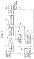
- FIG. 1 there is shown a block diagram of a scrambler incorporated in a transmitter, which processes a composite video signal to produce a scrambled video signal at its output end.
- the horizontal blanking pulses are included to blank out the retrace from right to left in each horizontal scanning line.
- the vertical blanking pulses blank out the scanning lines produced when an electron beam retraces vertically from bottom to top in each field.
- Each of the horizontal and the vertical blanking pulses contains a horizontal and a vertical synchronizing pulse.
- the horizontal synchronizing pulse at the end of each line determines the start of a horizontal retrace and the vertical synchronizing pulse at the end of each field determines the start of a vertical retrace.
- the composite video signal is distributed to an analog to digital (“A/D") converter 10 and a horizontal/vertical (“H/V”) blanking pulse detector 20.
- the A/D converter 10 digitally samples and converts the composite video signal into a number of N-bit video data samples.
- Each of the video data samples is applied to one input of an adder 12.
- the H/V blanking pulse detector 20 separates horizontal and vertical blanking pulses from the composite video signal and produces horizontal and vertical blanking detection signals.
- the horizontal and vertical detection signals are supplied to a scrambling data generator 30 and a parallel-to-serial data converter 18 through line 24.
- the scrambling data generator 30, which includes a seed signal generator 32 and a random data generator 34, generates scrambling data used to encrypt the video data samples.
- the seed signal generator 32 in response to each horizontal blanking detection signal, sequentially generates a seed signal.
- the seed signal from the seed signal generator 32 is provided to the parallel-to-serial data converter 18 through line 26 and the random data generator 34 which sequentially generates a corresponding number of scrambling data therein to the number of the video data samples.
- the seed signal serves as a "pointer" to point to a start location from which the scrambling data is sequentially derived from the random data generator 34.
- the pointer has separate position information which corresponds to the start location but randomly appoints the start location although the seed signal is generated from the seed signal generator 32 in a sequential order.
- the sequential order is initialized and repeated for each vertical blanking detection signal applied to the seed signal generator 32.
- the scrambling data at each location in the random data generator 34 has a value which is randomly assigned to encrypt the digitized video signal samples.
- each of the scrambling data in the random data generator 34 has values of 50, 5, -7, 40, 22, 2, 11, ..., 0, -17, 200 from the left side of the drawing; and that each of the seed signals SEs generated from the seed signal generator 32 has the position information assigned as 1, 3, 2, 6, 4, M-2 and so on.
- the seed signal SE1 is used as the pointer which appoints the start location 1 of the random data generator 34.
- the number of scrambling data is sequentially generated from the location "1" in the order of 50, 5, -7, Across, and 200.
- the seed signal SE with the position information of "M-2" is provided to the random data generator 34, the number of scrambling data is sequentially generated in the order of 0, -17, 200, 50, ..., 5 and so on.
- Each of the scrambling data from the random data generator 34 is sequentially provided to another input of the adder 12 in which each of the video data samples is added thereto.
- the added value by the adder 12 is provided as a scrambled video sample to a range regulator 14 which controls the scrambled video samples.
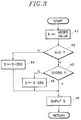
- the range regulator 14 The detailed operation of the range regulator 14 will be further described with reference to the flow diagram given in FIG. 3.
- the operation begins at block 41 where the added value of the adder 12 is set to a variable "S". And then, at block 42, it is determined whether or not the variable S is greater than or equal to the value "0". If not, the process flows to block 54 where the value "255" is added to the variable S. However, if the condition is met, the process goes to block 43.
- block 43 it is tested if the variable S is less than or equal to the value "255". If the test result is NO, the process proceeds to block 45 where the value "255" is subtracted from the variable S. However, if the test result is YES, the process goes to block 46. In block 46, the updated value S, i.e., the regulated scrambled video sample, is outputted to the parallel-to-serial data converter 18 through line 16 as shown in FIG. 1 and the process returns to block 41.
- the updated value S i.e., the regulated scrambled video sample
- the parallel-to-serial data converter 18, which may be of a multiplexer, receives and multiplexes the outputs from the range regulator 14, the seed signal generator 32 and the H/V blanking pulse detector 20.
- the resultant output of the multiplexer is supplied to a digital-to-analog ("D/A") converter 26 for the transmission of the scrambled video signal in analog form.
- D/A digital-to-analog
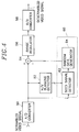
- FIG. 4 there is shown a block diagram of a descrambler incorporated in a receiver, which allows the recovery of the scrambled video signal by performing the reverse scrambling.
- the scrambled video signal transmitted from the scrambler is applied to an analog-to-digital ("A/D") converter 50 in which the scrambled video signal is sampled and converted into a number of scrambled video data samples.
- A/D analog-to-digital
- Each of the scrambled video data samples is fed to a horizontal/vertical ("H/V") blanking detector 52, a descrambling data generator 60 and one input end of a subtractor 54.
- H/V horizontal/vertical
- the H/V blanking detector 52 detects the presence of the horizontal and the vertical blanking detection signals contained in the scrambled video data samples and provides the horizontal and the vertical blanking detection signals to the descrambling data generator 60.
- the descrambling data generator 60 which includes a seed signal detector 62 and a random data generator 64, generates a corresponding number of descrambling data to the number of the scrambled video data samples, which has values exactly corresponding to those of the scrambling data.
- the seed signal detector 62 detects the presence of the seed signals contained in the scrambled video data samples and sequentially provides the detected seed signals to the random data generator 64, in synchronization with the horizontal blanking detection signals from the H/V blanking detector 52, respectively.
- the sequence of the seed signals is initialized and repeated for each of the vertical blanking detection signals applied to the seed signal detector 62.
- the seed signal has the separate location information which serves as a "pointer" to point to a start location as in the scrambling data generator 30 as shown in FIG. 1.
- the random data generator 64 in response to the seed signal, sequentially generates the descrambling data from each location cyclically starting from the start location assigned by the seed signal.
- each of the descrambling data from the random data generator 64 is provided to another input end of the subtractor 54 which serves to remove the scrambling data from the scrambled video data samples mixed therewith.
- the subtractor 54 subtracts the descrambling data from the scrambled video data sample to produce a descrambled video sample.
- the descrambled video sample is supplied to a range regulator 56. The detailed operation of the range regulator 56 will be described with reference to the flow diagram given in FIG. 5.
- the operation begins at block 71 where the subtracted value of the subtractor 54 is set to a variable "S". And then, at block 72, it is determined whether or not the variable S is greater than or equal to the value "0". If not, the process flows to block 74 where the value "255" is added to the variable S. However, if the condition is met, the process goes to block 73.
- the process proceeds to block 75 where the value "255" is subtracted from the variable S. However, if the test result is YES, the process goes to block 76.
- the updated value S i.e., the controlled descrambled video data sample
- D/A digital-to-analog
- the D/A converter 58 performs the conversion of the descrambled video data sample to produce a descrambled video signal in analog form which is reconstructed as is done with the composite video signal inputted to the scrambler shown in FIG. 1.
Landscapes
- Engineering & Computer Science (AREA)
- Signal Processing (AREA)
- Multimedia (AREA)
- Computer Networks & Wireless Communication (AREA)
- Two-Way Televisions, Distribution Of Moving Picture Or The Like (AREA)
- Circuits Of Receivers In General (AREA)
Abstract
Description
- The present invention relates to an apparatus for scrambling and descrambling a video signal; and, more particularly, to a scrambler for shuffling random data into digitized video signal samples and a descrambler for removing the random data from the digitized video signal samples.
- In subscription television broadcasting systems, there has been a constant need for a reliable method/device for scrambling or encrypting television signals at a transmitter and for descrambling or decoding the scrambled television signals at a receiver so that the television signals are protected against an unauthorized access. The above method/device for scrambling and descrambling the television signals is gaining its usages with increased frequencies in commercial applications such as television or satellite communications. For example, CATV signals are often scrambled so that a picture being transmitted can only be viewed by the users having an appropriate or authorized decoder.
- One of the prior art methods employed to scramble and descramble a video signal is disclosed in Europe Patent Application No. 0 356 200, in which the video signal in analog form is digitized into separate data packets for separate video lines. The data packets are sequentially inputted to a memory and the sequence read out from the memory is randomly intermixed.
- U.S. Patent No. 5,192,609 issued to Heun H. Mun offers a circuit for scrambling a digital TV signal. The scrambling circuit comprises a memory and a pseudo-random address generator for generating a pseudo-random address and a sequential address. The digital TV signal is written on the memory in accordance with the pseudo-random address and read out from the memory in accordance with the sequential address in order to form a scrambled TV signal, which is incorporated herein by reference.
- While the above and other prior art scrambling devices may be capable of performing their assigned task, they necessarily require a memory for use to change the sequence of the digital video signal. Therefore, needs have continued to exist for an improved video signal scrambling device which is more advantageous and desirable in terms of memory requirements and manufacturing costs.
- It is, therefore, an object of the invention to provide an apparatus for scrambling and descrambling a video signal without requiring a memory device to store digital video signals to be scrambled.
- It is another object of the invention to provide an apparatus for scrambling and descrambling a video signal by shuffling random data into the video signal and removing the random data from the video signal.
- In accordance with the present invention, there is provided a scrambler for scrambling a composite video signal, which comprises a detector for detecting horizontal and vertical blanking pulses from the composite video signal, an analog-to-digital converter for converting the composite video signal into a number of digital video samples, a scrambling data generator, in response to the horizontal blanking pulses, for generating a corresponding number of scrambling data, and an adder for adding each of the scrambling data into each of the digital video samples to produce a scrambled video signal.
- The above and other objects and features of the present invention will become apparent from the following description of preferred embodiments taken in conjunction with the accompanying drawings, in which:
- FIG. 1 shows a block diagram of the scrambler in accordance with the present invention;
- FIG. 2 exemplarily describes the generation of scrambling data through the use of a seed signal with location information;
- FIG. 3 is a flow diagram explaining the operation of the range regulator shown in FIG. 1;
- FIG. 4 presents a block diagram of the descrambler in accordance with the present invention; and
- FIG. 5 is a flow diagram representing the operation of the range regulator shown in FIG. 4.
- Referring to FIG. 1, there is shown a block diagram of a scrambler incorporated in a transmitter, which processes a composite video signal to produce a scrambled video signal at its output end. As is conventional, there are horizontal and vertical blanking pulses in the composite video signal. The horizontal blanking pulses are included to blank out the retrace from right to left in each horizontal scanning line. The vertical blanking pulses blank out the scanning lines produced when an electron beam retraces vertically from bottom to top in each field. Each of the horizontal and the vertical blanking pulses contains a horizontal and a vertical synchronizing pulse. The horizontal synchronizing pulse at the end of each line determines the start of a horizontal retrace and the vertical synchronizing pulse at the end of each field determines the start of a vertical retrace.
- The composite video signal is distributed to an analog to digital ("A/D")
converter 10 and a horizontal/vertical ("H/V")blanking pulse detector 20. The A/D converter 10 digitally samples and converts the composite video signal into a number of N-bit video data samples. Each of the N-bit video data samples, if said N is equal to 8, can have one of 256(= 2⁸) distinct quantities or values ranging from a decimal number "0" to "255" in a digital system. Each of the video data samples is applied to one input of anadder 12. - The H/V
blanking pulse detector 20 separates horizontal and vertical blanking pulses from the composite video signal and produces horizontal and vertical blanking detection signals. The horizontal and vertical detection signals are supplied to ascrambling data generator 30 and a parallel-to-serial data converter 18 throughline 24. Thescrambling data generator 30, which includes aseed signal generator 32 and arandom data generator 34, generates scrambling data used to encrypt the video data samples. Theseed signal generator 32, in response to each horizontal blanking detection signal, sequentially generates a seed signal. The seed signal from theseed signal generator 32 is provided to the parallel-to-serial data converter 18 throughline 26 and therandom data generator 34 which sequentially generates a corresponding number of scrambling data therein to the number of the video data samples. The seed signal serves as a "pointer" to point to a start location from which the scrambling data is sequentially derived from therandom data generator 34. The pointer has separate position information which corresponds to the start location but randomly appoints the start location although the seed signal is generated from theseed signal generator 32 in a sequential order. The sequential order is initialized and repeated for each vertical blanking detection signal applied to theseed signal generator 32. Also, the scrambling data at each location in therandom data generator 34 has a value which is randomly assigned to encrypt the digitized video signal samples. By way of illustration, in FIG. 2, it is assumed that each of the scrambling data in therandom data generator 34 has values of 50, 5, -7, 40, 22, 2, 11, ..., 0, -17, 200 from the left side of the drawing; and that each of the seed signals SEs generated from theseed signal generator 32 has the position information assigned as 1, 3, 2, 6, 4, M-2 and so on. The seed signal SE1 is used as the pointer which appoints thestart location 1 of therandom data generator 34. In response to the seed signal SE1, the number of scrambling data is sequentially generated from the location "1" in the order of 50, 5, -7, ....., and 200. Similarly, in case where the seed signal SE with the position information of "M-2" is provided to therandom data generator 34, the number of scrambling data is sequentially generated in the order of 0, -17, 200, 50, ..., 5 and so on. - Each of the scrambling data from the
random data generator 34 is sequentially provided to another input of theadder 12 in which each of the video data samples is added thereto. The added value by theadder 12 is provided as a scrambled video sample to arange regulator 14 which controls the scrambled video samples. - However, there may occur a situation that the scrambled video samples may go outside the range of "0" and "255" as a result of mixing the scrambling data with the video data sample. In accordance with the invention, the situation is controlled by the
range regulator 14. The detailed operation of therange regulator 14 will be further described with reference to the flow diagram given in FIG. 3. - In FIG. 3, the operation begins at
block 41 where the added value of theadder 12 is set to a variable "S". And then, atblock 42, it is determined whether or not the variable S is greater than or equal to the value "0". If not, the process flows toblock 54 where the value "255" is added to the variable S. However, if the condition is met, the process goes to block 43. - In
block 43, it is tested if the variable S is less than or equal to the value "255". If the test result is NO, the process proceeds to block 45 where the value "255" is subtracted from the variable S. However, if the test result is YES, the process goes to block 46. Inblock 46, the updated value S, i.e., the regulated scrambled video sample, is outputted to the parallel-to-serial data converter 18 throughline 16 as shown in FIG. 1 and the process returns toblock 41. - The parallel-to-
serial data converter 18, which may be of a multiplexer, receives and multiplexes the outputs from therange regulator 14, theseed signal generator 32 and the H/Vblanking pulse detector 20. The resultant output of the multiplexer is supplied to a digital-to-analog ("D/A")converter 26 for the transmission of the scrambled video signal in analog form. - Referring now to FIG. 4, there is shown a block diagram of a descrambler incorporated in a receiver, which allows the recovery of the scrambled video signal by performing the reverse scrambling.
- The scrambled video signal transmitted from the scrambler is applied to an analog-to-digital ("A/D")
converter 50 in which the scrambled video signal is sampled and converted into a number of scrambled video data samples. Each of the scrambled video data samples is fed to a horizontal/vertical ("H/V")blanking detector 52, adescrambling data generator 60 and one input end of asubtractor 54. - The H/
V blanking detector 52 detects the presence of the horizontal and the vertical blanking detection signals contained in the scrambled video data samples and provides the horizontal and the vertical blanking detection signals to thedescrambling data generator 60. - The
descrambling data generator 60, which includes aseed signal detector 62 and arandom data generator 64, generates a corresponding number of descrambling data to the number of the scrambled video data samples, which has values exactly corresponding to those of the scrambling data. Theseed signal detector 62 detects the presence of the seed signals contained in the scrambled video data samples and sequentially provides the detected seed signals to therandom data generator 64, in synchronization with the horizontal blanking detection signals from the H/V blanking detector 52, respectively. The sequence of the seed signals is initialized and repeated for each of the vertical blanking detection signals applied to theseed signal detector 62. It should be noted that the seed signal has the separate location information which serves as a "pointer" to point to a start location as in the scramblingdata generator 30 as shown in FIG. 1. Therandom data generator 64, in response to the seed signal, sequentially generates the descrambling data from each location cyclically starting from the start location assigned by the seed signal. - And then, each of the descrambling data from the
random data generator 64 is provided to another input end of thesubtractor 54 which serves to remove the scrambling data from the scrambled video data samples mixed therewith. Thesubtractor 54 subtracts the descrambling data from the scrambled video data sample to produce a descrambled video sample. The descrambled video sample is supplied to arange regulator 56. The detailed operation of therange regulator 56 will be described with reference to the flow diagram given in FIG. 5. - In FIG. 5, the operation begins at
block 71 where the subtracted value of thesubtractor 54 is set to a variable "S". And then, atblock 72, it is determined whether or not the variable S is greater than or equal to the value "0". If not, the process flows to block 74 where the value "255" is added to the variable S. However, if the condition is met, the process goes to block 73. - In
block 73, it is tested if the variable S is less than or equal to the value "255". If the test result is NO, the process proceeds to block 75 where the value "255" is subtracted from the variable S. However, if the test result is YES, the process goes to block 76. Inblock 76, the updated value S, i.e., the controlled descrambled video data sample, is outputted to a digital-to-analog ("D/A")converter 58 as shown in FIG. 4 and the process returns to block 71. The D/A converter 58 performs the conversion of the descrambled video data sample to produce a descrambled video signal in analog form which is reconstructed as is done with the composite video signal inputted to the scrambler shown in FIG. 1. - While the present invention has been shown and described with respect to the preferred embodiments, it will be apparent to those skilled in the art that many changes and modifications may be made without departing from the spirit and scope of the invention as defined in the appended claims.
Claims (8)
- A scrambler for scrambling a composite video signal to be transmitted to a receiver, which comprises:
means for detecting a horizontal and a vertical blanking pulse from the composite video signal to produce a horizontal and a vertical blanking detection signal;
means for converting the composite video signal into a number of video data samples, wherein each of the video data samples has one of a group of distinct quantities within a predetermined range;
scrambling data generator, in response to the horizontal and the vertical blanking detection signals, for generating a corresponding number of scrambling data to the number of video data samples; and
means for mixing each of the scrambling data into each of the video data samples to produce a scrambled video data sample. - The scrambler as recited in claim 1, wherein the scrambling data generator includes:
a seed signal generator for generating a seed signal for the horizontal blanking detection signal applied thereto, wherein the seed signal has separate location information and wherein the seed signal generator is initialized by the vertical blanking detection signal applied thereto;
a random data generator, in response to the seed signal, for sequentially generating the scrambling data at locations starting from a start location assigned by the location information. - The scrambler as recited in claim 2, wherein the scrambler further comprises a range regulator for controlling the quantity of the scrambled video data sample from said mixing means to fall within the predetermined range.
- The scrambler as recited in claim 3, wherein the scrambler further comprises:
means for multiplexing the scrambled video data sample, the seed signal and the horizontal and vertical blanking detection signals; and
means for converting the output of the multiplexing means into a scrambled video signal in analog form. - An apparatus for scrambling/descrambling a composite video signal, which comprises:
means for detecting a horizontal and a vertical blanking pulses from the composite video signal to produce a horizontal and a vertical blanking detection signal;
a first analog-to-digital converter for converting the composite video signal into a number of video data samples, wherein each of the video data samples has one of a group of distinct quantities within a predetermined range;
a scrambling data generator, in response to the horizontal and the blanking detection signals, for generating a seed signal for use to derive a corresponding number of scrambling data to the number of the video data samples;
an adder for mixing each of the scrambling data into each of the video data samples to produce a scrambled video data sample;
means for multiplexing the scrambled video data sample, the seed signal and the horizontal and vertical blanking detection signals;
a first digital-to-analog converter for converting the output of the multiplexing means into a scrambled video signal for the transmission thereof;
a second analog-to-digital converter for converting the transmitted scrambled video signal into a number of scrambled video data samples;
means for detecting the presence of the horizontal and vertical blanking detection signals contained in the scrambled video data samples;
a descrambling data generator, in response to the horizontal and the vertical blanking detection signals applied thereto, for generating a corresponding number of descrambling data to the number of the scrambled video data samples; and
a subtractor for subtracting each of the descrambling data from each of the scrambled video data samples to produce a descrambled video sample. - The apparatus as recited in claim 5, wherein the scrambling data generator includes:
a seed signal generator for generating the seed signal for the horizontal blanking detection signal, wherein the seed signal has separate location information and the seed signal generator is initialized by the vertical blanking detection signal applied thereto;
a random data generator, in response to the seed signal, for sequentially generating the scrambling data at locations starting from a start location assigned by the location information. - The apparatus as recited in claim 6, wherein the descrambling data generator includes:
a seed signal detector for detecting the presence of the seed signal contained in the scrambled video data samples and for providing the seed signal in synchronization with the horizontal blanking detection signal, wherein the seed signal has separated location information and the seed signal generator is initialized by the vertical blanking detection signal applied thereto;
a random data generator, in response to the seed signal, for sequentially generating the descrambling data at locations starting from a start location assigned by the location information. - The apparatus as recited in claim 7, wherein the apparatus further comprises:
a first range regulator for controlling the quantity of the scrambled video data sample from the adder to fall within the predetermined range; and
a second range regulator for controlling the quantity of the descrambled video data sample from the subtractor to fall within the predetermined range.
Applications Claiming Priority (2)
| Application Number | Priority Date | Filing Date | Title |
|---|---|---|---|
| KR1019930013510A KR960015357B1 (en) | 1993-07-16 | 1993-07-16 | Communication signal scrambling / descrambling communication device and communication method |
| KR9313510 | 1993-07-16 |
Publications (2)
| Publication Number | Publication Date |
|---|---|
| EP0634869A1 true EP0634869A1 (en) | 1995-01-18 |
| EP0634869B1 EP0634869B1 (en) | 1999-09-29 |
Family
ID=19359464
Family Applications (1)
| Application Number | Title | Priority Date | Filing Date |
|---|---|---|---|
| EP94111175A Expired - Lifetime EP0634869B1 (en) | 1993-07-16 | 1994-07-18 | Apparatus for scrambling and descrambling a video signal |
Country Status (5)
| Country | Link |
|---|---|
| US (1) | US5561713A (en) |
| EP (1) | EP0634869B1 (en) |
| JP (1) | JPH0767097A (en) |
| KR (1) | KR960015357B1 (en) |
| DE (1) | DE69420907D1 (en) |
Cited By (1)
| Publication number | Priority date | Publication date | Assignee | Title |
|---|---|---|---|---|
| GB2382753A (en) * | 2001-12-03 | 2003-06-04 | Sony Uk Ltd | Encrypting video data, ensuring that all encrypted data values lie in a legal range |
Families Citing this family (52)
| Publication number | Priority date | Publication date | Assignee | Title |
|---|---|---|---|---|
| JPH08195735A (en) * | 1995-01-18 | 1996-07-30 | Toshiba Corp | Decoder device |
| US5774549A (en) * | 1995-12-04 | 1998-06-30 | Sun Microsystems, Inc. | Method and apparatus that processes a video signal to generate a random number generator seed |
| US6020189A (en) * | 1996-08-30 | 2000-02-01 | The Johns Hopkins University School Of Medicine | Fibroblast growth factor homologous factors (FHFs) and methods of use |
| US5978480A (en) * | 1996-08-30 | 1999-11-02 | Vtech Communications, Ltd. | System for scrambling and descrambling video signals by altering synchronization patterns |
| US6249582B1 (en) | 1997-12-31 | 2001-06-19 | Transcrypt International, Inc. | Apparatus for and method of overhead reduction in a block cipher |
| US6215876B1 (en) | 1997-12-31 | 2001-04-10 | Transcrypt International, Inc. | Apparatus for and method of detecting initialization vector errors and maintaining cryptographic synchronization without substantial increase in overhead |
| US7730300B2 (en) | 1999-03-30 | 2010-06-01 | Sony Corporation | Method and apparatus for protecting the transfer of data |
| US7565546B2 (en) | 1999-03-30 | 2009-07-21 | Sony Corporation | System, method and apparatus for secure digital content transmission |
| US6697489B1 (en) | 1999-03-30 | 2004-02-24 | Sony Corporation | Method and apparatus for securing control words |
| US6912655B1 (en) | 1999-08-09 | 2005-06-28 | Tristrata Security Inc. | Network security architecture system utilizing seals |
| US7039614B1 (en) | 1999-11-09 | 2006-05-02 | Sony Corporation | Method for simulcrypting scrambled data to a plurality of conditional access devices |
| US7225164B1 (en) | 2000-02-15 | 2007-05-29 | Sony Corporation | Method and apparatus for implementing revocation in broadcast networks |
| US20030053927A1 (en) * | 2000-03-31 | 2003-03-20 | Dober Chemical Corporation | Controlled Rellease of oxygen scavengers in cooling systems |
| US20030206631A1 (en) * | 2000-06-22 | 2003-11-06 | Candelore Brant L. | Method and apparatus for scrambling program data for furture viewing |
| US7747853B2 (en) | 2001-06-06 | 2010-06-29 | Sony Corporation | IP delivery of secure digital content |
| US7127619B2 (en) | 2001-06-06 | 2006-10-24 | Sony Corporation | Decoding and decryption of partially encrypted information |
| US7895616B2 (en) | 2001-06-06 | 2011-02-22 | Sony Corporation | Reconstitution of program streams split across multiple packet identifiers |
| US7350082B2 (en) | 2001-06-06 | 2008-03-25 | Sony Corporation | Upgrading of encryption |
| US7155012B2 (en) | 2002-01-02 | 2006-12-26 | Sony Corporation | Slice mask and moat pattern partial encryption |
| US7215770B2 (en) | 2002-01-02 | 2007-05-08 | Sony Corporation | System and method for partially encrypted multimedia stream |
| US7218738B2 (en) | 2002-01-02 | 2007-05-15 | Sony Corporation | Encryption and content control in a digital broadcast system |
| US7039938B2 (en) | 2002-01-02 | 2006-05-02 | Sony Corporation | Selective encryption for video on demand |
| US7302059B2 (en) | 2002-01-02 | 2007-11-27 | Sony Corporation | Star pattern partial encryption |
| US7233669B2 (en) | 2002-01-02 | 2007-06-19 | Sony Corporation | Selective encryption to enable multiple decryption keys |
| US7292690B2 (en) | 2002-01-02 | 2007-11-06 | Sony Corporation | Video scene change detection |
| US7765567B2 (en) | 2002-01-02 | 2010-07-27 | Sony Corporation | Content replacement by PID mapping |
| US7292691B2 (en) | 2002-01-02 | 2007-11-06 | Sony Corporation | Progressive video refresh slice detection |
| US7242773B2 (en) | 2002-09-09 | 2007-07-10 | Sony Corporation | Multiple partial encryption using retuning |
| US7376233B2 (en) | 2002-01-02 | 2008-05-20 | Sony Corporation | Video slice and active region based multiple partial encryption |
| US7823174B2 (en) | 2002-01-02 | 2010-10-26 | Sony Corporation | Macro-block based content replacement by PID mapping |
| US7530084B2 (en) | 2002-05-28 | 2009-05-05 | Sony Corporation | Method and apparatus for synchronizing dynamic graphics |
| US8818896B2 (en) | 2002-09-09 | 2014-08-26 | Sony Corporation | Selective encryption with coverage encryption |
| US8572408B2 (en) | 2002-11-05 | 2013-10-29 | Sony Corporation | Digital rights management of a digital device |
| US7724907B2 (en) | 2002-11-05 | 2010-05-25 | Sony Corporation | Mechanism for protecting the transfer of digital content |
| US8645988B2 (en) | 2002-12-13 | 2014-02-04 | Sony Corporation | Content personalization for digital content |
| US8667525B2 (en) | 2002-12-13 | 2014-03-04 | Sony Corporation | Targeted advertisement selection from a digital stream |
| US7409702B2 (en) | 2003-03-20 | 2008-08-05 | Sony Corporation | Auxiliary program association table |
| US7292692B2 (en) | 2003-03-25 | 2007-11-06 | Sony Corporation | Content scrambling with minimal impact on legacy devices |
| JP4517779B2 (en) * | 2003-09-12 | 2010-08-04 | 日本ビクター株式会社 | Information transmission method |
| US7286667B1 (en) | 2003-09-15 | 2007-10-23 | Sony Corporation | Decryption system |
| US7853980B2 (en) | 2003-10-31 | 2010-12-14 | Sony Corporation | Bi-directional indices for trick mode video-on-demand |
| US7343013B2 (en) | 2003-12-16 | 2008-03-11 | Sony Corporation | Composite session-based encryption of video on demand content |
| US7620180B2 (en) | 2003-11-03 | 2009-11-17 | Sony Corporation | Preparation of content for multiple conditional access methods in video on demand |
| US7346163B2 (en) | 2003-10-31 | 2008-03-18 | Sony Corporation | Dynamic composition of pre-encrypted video on demand content |
| US7263187B2 (en) | 2003-10-31 | 2007-08-28 | Sony Corporation | Batch mode session-based encryption of video on demand content |
| US7895617B2 (en) | 2004-12-15 | 2011-02-22 | Sony Corporation | Content substitution editor |
| US8041190B2 (en) | 2004-12-15 | 2011-10-18 | Sony Corporation | System and method for the creation, synchronization and delivery of alternate content |
| US7502466B2 (en) * | 2005-01-06 | 2009-03-10 | Toshiba Corporation | System and method for secure communication of electronic documents |
| US20090210695A1 (en) * | 2005-01-06 | 2009-08-20 | Amir Shahindoust | System and method for securely communicating electronic documents to an associated document processing device |
| US8185921B2 (en) | 2006-02-28 | 2012-05-22 | Sony Corporation | Parental control of displayed content using closed captioning |
| US7555464B2 (en) | 2006-03-01 | 2009-06-30 | Sony Corporation | Multiple DRM management |
| US20250047471A1 (en) * | 2023-07-31 | 2025-02-06 | Texas Instruments Incorporated | Protected Sensor Data Communication |
Citations (3)
| Publication number | Priority date | Publication date | Assignee | Title |
|---|---|---|---|---|
| US4605961A (en) * | 1983-12-22 | 1986-08-12 | Frederiksen Jeffrey E | Video transmission system using time-warp scrambling |
| US4636852A (en) * | 1984-01-26 | 1987-01-13 | Scientific-Atlanta, Inc. | Scrambling and descrambling of television signals for subscription TV |
| EP0356200A1 (en) * | 1988-08-24 | 1990-02-28 | Screen Electronics Limited | Video scrambling system |
Family Cites Families (3)
| Publication number | Priority date | Publication date | Assignee | Title |
|---|---|---|---|---|
| DE3343307A1 (en) * | 1983-11-30 | 1985-06-05 | Blaupunkt-Werke Gmbh, 3200 Hildesheim | METHOD FOR ENCRYPTING AND DECRYLING ANALOG SIGNALS, AND CIRCUIT ARRANGEMENT FOR IMPLEMENTING THE METHOD |
| KR0152270B1 (en) * | 1990-04-30 | 1998-10-15 | 구자홍 | Synthetic Video Signal Decryption Processing System of Pay TV System |
| JPH0644755A (en) * | 1992-07-24 | 1994-02-18 | Sony Corp | Method for transmitting video signal and recorder therefor |
-
1993
- 1993-07-16 KR KR1019930013510A patent/KR960015357B1/en not_active Expired - Fee Related
-
1994
- 1994-07-15 JP JP6164161A patent/JPH0767097A/en active Pending
- 1994-07-18 DE DE69420907T patent/DE69420907D1/en not_active Expired - Lifetime
- 1994-07-18 EP EP94111175A patent/EP0634869B1/en not_active Expired - Lifetime
- 1994-07-18 US US08/276,236 patent/US5561713A/en not_active Expired - Fee Related
Patent Citations (3)
| Publication number | Priority date | Publication date | Assignee | Title |
|---|---|---|---|---|
| US4605961A (en) * | 1983-12-22 | 1986-08-12 | Frederiksen Jeffrey E | Video transmission system using time-warp scrambling |
| US4636852A (en) * | 1984-01-26 | 1987-01-13 | Scientific-Atlanta, Inc. | Scrambling and descrambling of television signals for subscription TV |
| EP0356200A1 (en) * | 1988-08-24 | 1990-02-28 | Screen Electronics Limited | Video scrambling system |
Cited By (3)
| Publication number | Priority date | Publication date | Assignee | Title |
|---|---|---|---|---|
| GB2382753A (en) * | 2001-12-03 | 2003-06-04 | Sony Uk Ltd | Encrypting video data, ensuring that all encrypted data values lie in a legal range |
| WO2003049440A1 (en) * | 2001-12-03 | 2003-06-12 | Sony United Kingdom Limited | Data coding |
| US7466822B2 (en) | 2001-12-03 | 2008-12-16 | Sony United Kingdom Limited | Data coding |
Also Published As
| Publication number | Publication date |
|---|---|
| JPH0767097A (en) | 1995-03-10 |
| US5561713A (en) | 1996-10-01 |
| KR960015357B1 (en) | 1996-11-09 |
| DE69420907D1 (en) | 1999-11-04 |
| KR950004795A (en) | 1995-02-18 |
| EP0634869B1 (en) | 1999-09-29 |
Similar Documents
| Publication | Publication Date | Title |
|---|---|---|
| US5561713A (en) | Apparatus for scrambling and descrambling a video signal | |
| AU645943B2 (en) | Conversion of television signal formats with retention of common control data stream | |
| US5930361A (en) | Video inversion detection apparatus and method | |
| US6055315A (en) | Distributed scrambling method and system | |
| CA2077689C (en) | Television scrambler | |
| US4864614A (en) | Authorising coded signals | |
| EP0099691B1 (en) | Method for encrypting a line-scanned television signal and encrypting and decrypting apparatus | |
| JPH06105308A (en) | Method and apparatus for encoding and decoding of video signal using edge fill | |
| US4646147A (en) | Method and apparatus for scrambling and unscrambling television signals | |
| JPH0683449B2 (en) | Cable Television System | |
| EP0222818A1 (en) | Method and apparatus for scrambling and descrambling television signals | |
| WO1993011641A1 (en) | Method and apparatus for displaying channel identification information | |
| US5651065A (en) | Insertion of supplemental burst into video signals to thwart piracy and/or carry data | |
| GB2140656A (en) | Television transmission system | |
| US4467353A (en) | Television signal scrambling system and method | |
| JP2004048771A (en) | Methods for preventing duplication of digital signals | |
| EP0518129B1 (en) | Method and apparatus for enhancing the security of a scrambled television signal | |
| US5617475A (en) | Scrambling and descrambling of video signals using horizontal line combinations | |
| HK1008413B (en) | Method and apparatus for enhancing the security of a scrambled television signal | |
| US5978480A (en) | System for scrambling and descrambling video signals by altering synchronization patterns | |
| US5598472A (en) | Charge-coupled-device based all-analog wave form scrambling with applications in audio, video, video-on-demand, and TV systems | |
| CA1204162A (en) | Audio scrambler utilizing an auxiliary channel for synchronizing the descrambler | |
| KR950012668B1 (en) | Video signal scrambler and descrambler | |
| KR100284178B1 (en) | Video signal scrambler and descrambler | |
| KR930005749B1 (en) | Picture image compensation system by scambling |
Legal Events
| Date | Code | Title | Description |
|---|---|---|---|
| PUAI | Public reference made under article 153(3) epc to a published international application that has entered the european phase |
Free format text: ORIGINAL CODE: 0009012 |
|
| AK | Designated contracting states |
Kind code of ref document: A1 Designated state(s): DE FR GB NL |
|
| 17P | Request for examination filed |
Effective date: 19950718 |
|
| 17Q | First examination report despatched |
Effective date: 19970602 |
|
| GRAG | Despatch of communication of intention to grant |
Free format text: ORIGINAL CODE: EPIDOS AGRA |
|
| GRAG | Despatch of communication of intention to grant |
Free format text: ORIGINAL CODE: EPIDOS AGRA |
|
| GRAH | Despatch of communication of intention to grant a patent |
Free format text: ORIGINAL CODE: EPIDOS IGRA |
|
| GRAH | Despatch of communication of intention to grant a patent |
Free format text: ORIGINAL CODE: EPIDOS IGRA |
|
| GRAA | (expected) grant |
Free format text: ORIGINAL CODE: 0009210 |
|
| AK | Designated contracting states |
Kind code of ref document: B1 Designated state(s): DE FR GB NL |
|
| PG25 | Lapsed in a contracting state [announced via postgrant information from national office to epo] |
Ref country code: NL Free format text: LAPSE BECAUSE OF FAILURE TO SUBMIT A TRANSLATION OF THE DESCRIPTION OR TO PAY THE FEE WITHIN THE PRESCRIBED TIME-LIMIT Effective date: 19990929 Ref country code: FR Free format text: LAPSE BECAUSE OF FAILURE TO SUBMIT A TRANSLATION OF THE DESCRIPTION OR TO PAY THE FEE WITHIN THE PRESCRIBED TIME-LIMIT Effective date: 19990929 |
|
| REF | Corresponds to: |
Ref document number: 69420907 Country of ref document: DE Date of ref document: 19991104 |
|
| PG25 | Lapsed in a contracting state [announced via postgrant information from national office to epo] |
Ref country code: DE Free format text: LAPSE BECAUSE OF FAILURE TO SUBMIT A TRANSLATION OF THE DESCRIPTION OR TO PAY THE FEE WITHIN THE PRESCRIBED TIME-LIMIT Effective date: 19991230 |
|
| EN | Fr: translation not filed | ||
| NLV1 | Nl: lapsed or annulled due to failure to fulfill the requirements of art. 29p and 29m of the patents act | ||
| PLBE | No opposition filed within time limit |
Free format text: ORIGINAL CODE: 0009261 |
|
| STAA | Information on the status of an ep patent application or granted ep patent |
Free format text: STATUS: NO OPPOSITION FILED WITHIN TIME LIMIT |
|
| 26N | No opposition filed | ||
| PGFP | Annual fee paid to national office [announced via postgrant information from national office to epo] |
Ref country code: GB Payment date: 20010718 Year of fee payment: 8 |
|
| REG | Reference to a national code |
Ref country code: GB Ref legal event code: IF02 |
|
| PG25 | Lapsed in a contracting state [announced via postgrant information from national office to epo] |
Ref country code: GB Free format text: LAPSE BECAUSE OF NON-PAYMENT OF DUE FEES Effective date: 20020718 |
|
| GBPC | Gb: european patent ceased through non-payment of renewal fee |
Effective date: 20020718 |