EP0634832A1 - Method for driving stepping motor of multiphase hybrid type - Google Patents
Method for driving stepping motor of multiphase hybrid type Download PDFInfo
- Publication number
- EP0634832A1 EP0634832A1 EP94905245A EP94905245A EP0634832A1 EP 0634832 A1 EP0634832 A1 EP 0634832A1 EP 94905245 A EP94905245 A EP 94905245A EP 94905245 A EP94905245 A EP 94905245A EP 0634832 A1 EP0634832 A1 EP 0634832A1
- Authority
- EP
- European Patent Office
- Prior art keywords
- teeth
- fixed magnetic
- small teeth
- magnetic poles
- pole
- Prior art date
- Legal status (The legal status is an assumption and is not a legal conclusion. Google has not performed a legal analysis and makes no representation as to the accuracy of the status listed.)
- Granted
Links
Images


Classifications
-
- H—ELECTRICITY
- H02—GENERATION; CONVERSION OR DISTRIBUTION OF ELECTRIC POWER
- H02K—DYNAMO-ELECTRIC MACHINES
- H02K37/00—Motors with rotor rotating step by step and without interrupter or commutator driven by the rotor, e.g. stepping motors
- H02K37/02—Motors with rotor rotating step by step and without interrupter or commutator driven by the rotor, e.g. stepping motors of variable reluctance type
- H02K37/04—Motors with rotor rotating step by step and without interrupter or commutator driven by the rotor, e.g. stepping motors of variable reluctance type with rotors situated within the stators
-
- H—ELECTRICITY
- H02—GENERATION; CONVERSION OR DISTRIBUTION OF ELECTRIC POWER
- H02K—DYNAMO-ELECTRIC MACHINES
- H02K37/00—Motors with rotor rotating step by step and without interrupter or commutator driven by the rotor, e.g. stepping motors
- H02K37/10—Motors with rotor rotating step by step and without interrupter or commutator driven by the rotor, e.g. stepping motors of permanent magnet type
- H02K37/12—Motors with rotor rotating step by step and without interrupter or commutator driven by the rotor, e.g. stepping motors of permanent magnet type with stationary armatures and rotating magnets
- H02K37/14—Motors with rotor rotating step by step and without interrupter or commutator driven by the rotor, e.g. stepping motors of permanent magnet type with stationary armatures and rotating magnets with magnets rotating within the armatures
- H02K37/18—Motors with rotor rotating step by step and without interrupter or commutator driven by the rotor, e.g. stepping motors of permanent magnet type with stationary armatures and rotating magnets with magnets rotating within the armatures of homopolar type
Definitions
- the present invention relates to an improved method of driving a 5-phase hybrid stepping motor.
- Hybrid stepping motors have been well known for over a quarter of the century as actuators appropriated for highly accurate positioning movements.
- the hybrid stepping motors are widely used in various machine tools, e.g. with fully automated production lines, as well as computer related instruments including printers, plotters, facsimile machines, and disk drive units.
- the conventional four- or five-phase stepping motors however have some disadvantages that torque stiffness is unstable, that static torque is varied depending on the stop position, and that the step angle is not at a high accuracy. It is an object of the present invention to eliminate the foregoing disadvantages.
- a method of driving a multi-phase hybrid type stepping motor which has a rotor provided with one or more permanent magnets magnetized in the rotating direction of a rotary shaft is characterized by a two pole caps mounted to both ends of the permanent magnet respectively, each the pole cap made of a soft magnetic material and having a plurality (NR) of teeth arranged at equal intervals on the circumferential surface thereof, the teeth of the two pole caps being displaced by 1/2 of the teeth pitch (1/2 Tp) from each other, a plurality of stator segments of an asymmetrical form disposed around the rotor, each the asymmetrical stator segment having ten fixed magnetic poles thereof extending inwardly and radially, each the fixed magnetic pole having a winding wound thereon with no taps and being provided with two or more small teeth arranged at equal intervals of the same pitch as of the teeth of the rotor, the total number (NS) of the small teeth of the asymmetrical stator segment being determined by
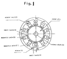
- Fig. 1 is a cross sectional view showing one embodiment of the present invention:
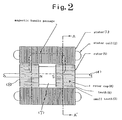
- Fig. 2 is a longitudinal sectional view of the embodiment of the present invention:
- Fig. 3 is a front view of a stator system another embodiment of the present invention:
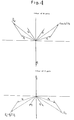
- Fig. 4 is a vector diagram of a rotor in the embodiment of the present invention:
- Fig. 5 is a wiring diagram according to the embodiment of the present invention:
- Fig. 6 is a chart showing the magnetic shift at fixed magnetic poles in full-step mode: and
- Fig. 7 is a chart showing the magnetic shift at the fixed magnetic poles in half-step mode.
- Figs. 1 and 2 illustrate in cross section a stepping motor according to the present invention.
- Fig. 1 is a cross sectional view taken along the line extending at a right angle to a rotary shaft 4.
- a stator 1 has ten fixed magnetic poles S, S' arranged inwardly thereof.
- the fixed magnetic pole S or S' has a stator coil 2 wound thereon and is provided at inward end with a set of small teeth 3. It is assumed that the total number of the small teeth 3 is NS.
- the rotary shaft 4 has a rotor 5 mounted at center thereto.
- the rotor 5 has a permanent magnet 7 mounted to the axial center thereof and two rotor caps 8 fitted to both sides of the magnet 7 respectively, as best shown in Fig. 2.
- Fig. 1 is a cross sectional view taken along the line A-A of Fig. 2.
- the ten stator coils 2 are numbered from P1 to P10.
- the number of the small teeth 3 of each alternate one of the ten fixed magnetic poles is increased by one while that of the other fixed magnetic poles is kept 4 (forming an asymmetrical fixed magnetic pole arrangement of the stator).
- the 4-teeth fixed magnetic pole S is disposed opposite to the 5-teeth fixed magnetic pole S' (Fig. 3).
- the difference of the teeth between the rotor 5 and the fixed magnetic poles S,S' is 5 (as calculated by subtracting 4x5 from 50 and then, 5x5 from the result).
- This embodiment also offers an improvement in the stability at torque equilibrium position. The reason is that while at least two adjacent fixed magnetic poles are polarized to N, other two adjacent fixed magnetic poles are turned to S (Fig. 6).
- a second embodiment is characterized by the shift angle between two adjacent fixed magnetic poles which is equal to 3/10 Tp or 7/10 Tp. Equally, the number of the small teeth 3 of every alternate one of the fixed magnetic poles is increased by one.
- the difference of teeth between the rotor and the stator is preferably 5 or 3.
- a radial stress exerted on the rotor caps is divided into three directions.
- the stress is evenly applied to the two rotor caps.
- the three directional components of the stress may less affect the manufacturing tolerance. Thereby, the step angle accuracy will increase and unwanted vibration will be reduced. This is because there are provided only three large distanced slots between the fixed magnetic poles.
- Fig. 6 shows the polarization of the fixed magnetic poles during a series of 20 consecutive steps. The full 20 steps perform one rotation of the rotary shaft 4.
- the number of N poles is identical to the number of S poles in the stepping motor at every position or step. This results in reduction of the hysteresis.
- Fig. 5 is a wiring diagram according to the embodiment of the present invention.
- the ten fixed magnetic poles are coupled to one another in a circular order of P3, P8, P6, P1, P9, P4, P2, P7, P5, and P10.
- Five, blue, red, orange, green, and black colored, terminals are provided between P10 and P3, P8 and P6, P1 and P9, P4 and P2, and P7 and P5 respectively.
- Fig. 6 is a diagram showing the polarization of the fixed magnetic poles in a full step mode.
- the dots in Fig. 5 represent the direction of coil windings.
- Each of the blue, red, orange, green, and black colored terminals is coupled to a two-throw switch which normally stays in the neutral mode and is turned to one position for connecting to a positive source and to the other position for connecting to a negative source, although its switching circuit is not shown in Fig. 5.
- the switch is selectively connected to one of the three positions by a command signal from an unshown control unit. Accordingly, the ten magnetic poles are energized to have polarities as shown in Fig. 6 at each step. The switching action at the step produces the two polar states of the same number.
- Fig. 7 is a diagram showing the polarization of the fixed magnetic poles at the steps in a half step mode.
- the present invention with the foregoing arrangement allows the torque stiffness to be stable, the static torque to be equilibrated, and the step angle to be at high accuracy.
- the S and N poles of the same number are produced at each step of the movement. This will minimize abnormal vibration during the rotating movement.
- the static torque acts in equilibrium and the step angle stays at high accuracy.
- the S and N poles become equal in the number in the full and half step modes, abnormal vibration during the rotating movement will be minimized.
Landscapes
- Engineering & Computer Science (AREA)
- Power Engineering (AREA)
- Control Of Stepping Motors (AREA)
Abstract
Description
- The present invention relates to an improved method of driving a 5-phase hybrid stepping motor.
- Hybrid stepping motors have been well known for over a quarter of the century as actuators appropriated for highly accurate positioning movements. The hybrid stepping motors are widely used in various machine tools, e.g. with fully automated production lines, as well as computer related instruments including printers, plotters, facsimile machines, and disk drive units.
- For increasing the versatility in use, there is made an attempt to minimize the step angle of such a hybrid stepping motor. To this respect, four- and five-phase types of the stepping motor are now commonly provided.
- The conventional four- or five-phase stepping motors however have some disadvantages that torque stiffness is unstable, that static torque is varied depending on the stop position, and that the step angle is not at a high accuracy. It is an object of the present invention to eliminate the foregoing disadvantages.
- For achievement of the above object, a method of driving a multi-phase hybrid type stepping motor which has a rotor provided with one or more permanent magnets magnetized in the rotating direction of a rotary shaft, according to the present invention, is characterized by a two pole caps mounted to both ends of the permanent magnet respectively, each the pole cap made of a soft magnetic material and having a plurality (NR) of teeth arranged at equal intervals on the circumferential surface thereof, the teeth of the two pole caps being displaced by 1/2 of the teeth pitch (1/2 Tp) from each other, a plurality of stator segments of an asymmetrical form disposed around the rotor, each the asymmetrical stator segment having ten fixed magnetic poles thereof extending inwardly and radially, each the fixed magnetic pole having a winding wound thereon with no taps and being provided with two or more small teeth arranged at equal intervals of the same pitch as of the teeth of the rotor, the total number (NS) of the small teeth of the asymmetrical stator segment being determined by


- Fig. 1 is a cross sectional view showing one embodiment of the present invention: Fig. 2 is a longitudinal sectional view of the embodiment of the present invention: Fig. 3 is a front view of a stator system another embodiment of the present invention: Fig. 4 is a vector diagram of a rotor in the embodiment of the present invention: Fig. 5 is a wiring diagram according to the embodiment of the present invention: Fig. 6 is a chart showing the magnetic shift at fixed magnetic poles in full-step mode: and Fig. 7 is a chart showing the magnetic shift at the fixed magnetic poles in half-step mode.
- Preferred embodiments of the present invention will be described in more details referring to the accompanying drawings.
- Figs. 1 and 2 illustrate in cross section a stepping motor according to the present invention. Fig. 1 is a cross sectional view taken along the line extending at a right angle to a
rotary shaft 4. As shown, astator 1 has ten fixed magnetic poles S, S' arranged inwardly thereof. The fixed magnetic pole S or S' has astator coil 2 wound thereon and is provided at inward end with a set ofsmall teeth 3. It is assumed that the total number of thesmall teeth 3 is NS. Therotary shaft 4 has arotor 5 mounted at center thereto. Therotor 5 has apermanent magnet 7 mounted to the axial center thereof and tworotor caps 8 fitted to both sides of themagnet 7 respectively, as best shown in Fig. 2. Therotor caps 8 have a plurality ofteeth 6 provided on the circumferential surface thereof. It is now assumed that the total number of theteeth 6 is NR. Fig. 1 is a cross sectional view taken along the line A-A of Fig. 2. The tenstator coils 2 are numbered from P1 to P10. - A first embodiment of the present invention is intended to have a five-phase stepping motor with the ten fixed magnetic poles S, S' improved in the torque stiffness, the step angle precision, and the efficiency of movement when NR=50 (where a shift angle between two adjacent fixed magnetic poles is 1/5Tp, Tp being a pitch of the small teeth 3). In particular, the number of the
small teeth 3 of each alternate one of the ten fixed magnetic poles is increased by one while that of the other fixed magnetic poles is kept 4 (forming an asymmetrical fixed magnetic pole arrangement of the stator). Accordingly, the 4-teeth fixed magnetic pole S is disposed opposite to the 5-teeth fixed magnetic pole S' (Fig. 3). - The difference of the teeth between the
rotor 5 and the fixed magnetic poles S,S' is 5 (as calculated by subtracting 4x5 from 50 and then, 5x5 from the result). - This embodiment also offers an improvement in the stability at torque equilibrium position. The reason is that while at least two adjacent fixed magnetic poles are polarized to N, other two adjacent fixed magnetic poles are turned to S (Fig. 6).
- As compared with the first embodiment in which the improvement in the four different respects is ensured with the rotor having 40, 50, 80, 90, or 100 of the teeth, using such an asymmetrical arrangement of the ten fixed magnetic poles of the stator, a second embodiment is characterized by the shift angle between two adjacent fixed magnetic poles which is equal to 3/10 Tp or 7/10 Tp. Equally, the number of the
small teeth 3 of every alternate one of the fixed magnetic poles is increased by one. - For determining an optimum degree of the step angle for performance of a stepping motor, the difference of teeth between the rotor and the stator is preferably 5 or 3.
- As shown in Fig. 4, a radial stress exerted on the rotor caps is divided into three directions. The stress is evenly applied to the two rotor caps. The three directional components of the stress may less affect the manufacturing tolerance. Thereby, the step angle accuracy will increase and unwanted vibration will be reduced. This is because there are provided only three large distanced slots between the fixed magnetic poles. Fig. 6 shows the polarization of the fixed magnetic poles during a series of 20 consecutive steps. The full 20 steps perform one rotation of the
rotary shaft 4. As apparent from Fig. 6, the number of N poles is identical to the number of S poles in the stepping motor at every position or step. This results in reduction of the hysteresis. - The step-by-step rotating movement will now be described referring to Figs. 5 and 6. Fig. 5 is a wiring diagram according to the embodiment of the present invention. The ten fixed magnetic poles are coupled to one another in a circular order of P3, P8, P6, P1, P9, P4, P2, P7, P5, and P10. Five, blue, red, orange, green, and black colored, terminals are provided between P10 and P3, P8 and P6, P1 and P9, P4 and P2, and P7 and P5 respectively. Fig. 6 is a diagram showing the polarization of the fixed magnetic poles in a full step mode. The dots in Fig. 5 represent the direction of coil windings.
- Each of the blue, red, orange, green, and black colored terminals is coupled to a two-throw switch which normally stays in the neutral mode and is turned to one position for connecting to a positive source and to the other position for connecting to a negative source, although its switching circuit is not shown in Fig. 5. The switch is selectively connected to one of the three positions by a command signal from an unshown control unit. Accordingly, the ten magnetic poles are energized to have polarities as shown in Fig. 6 at each step. The switching action at the step produces the two polar states of the same number.
- Fig. 7 is a diagram showing the polarization of the fixed magnetic poles at the steps in a half step mode.
- As set forth above, the present invention with the foregoing arrangement allows the torque stiffness to be stable, the static torque to be equilibrated, and the step angle to be at high accuracy. In both the full and half step modes, the S and N poles of the same number are produced at each step of the movement. This will minimize abnormal vibration during the rotating movement.
- As the specific teeth arrangements of the rotor and the stator are provided in a combination, the static torque acts in equilibrium and the step angle stays at high accuracy. In addition, the S and N poles become equal in the number in the full and half step modes, abnormal vibration during the rotating movement will be minimized.
Claims (1)
- A method of driving a multi-phase hybrid type stepping motor which has a rotor provided with one or more permanent magnets magnetized in the rotating direction of a rotary shaft, characterized by a two pole caps mounted to both ends of the permanent magnet respectively, each the pole cap made of a soft magnetic material and having a plurality (NR) of teeth arranged at equal intervals on the circumferential surface thereof, the teeth of the two pole caps being displaced by 1/2 of the teeth pitch (1/2 Tp) from each other, a plurality of stator segments of an asymmetrical form disposed around the rotor, each the asymmetrical stator segment having ten fixed magnetic poles thereof extending inwardly and radially, each the fixed magnetic pole having a winding wound thereon with no taps and being provided with two or more small teeth arranged at equal intervals of the same pitch as of the teeth of the rotor, the total number (NS) of the small teeth of the asymmetrical stator segment being determined by


Applications Claiming Priority (3)
| Application Number | Priority Date | Filing Date | Title |
|---|---|---|---|
| JP5036059A JPH06245468A (en) | 1993-02-01 | 1993-02-01 | Method for driving polyphase hybrid type stepping motor |
| JP36059/93 | 1993-02-01 | ||
| PCT/JP1994/000141 WO1994018745A1 (en) | 1993-02-01 | 1994-02-01 | Method for driving stepping motor of multiphase hybrid type |
Publications (3)
| Publication Number | Publication Date |
|---|---|
| EP0634832A1 true EP0634832A1 (en) | 1995-01-18 |
| EP0634832A4 EP0634832A4 (en) | 1995-06-28 |
| EP0634832B1 EP0634832B1 (en) | 1998-07-22 |
Family
ID=12459153
Family Applications (1)
| Application Number | Title | Priority Date | Filing Date |
|---|---|---|---|
| EP94905245A Expired - Lifetime EP0634832B1 (en) | 1993-02-01 | 1994-02-01 | Stepping motor of multiphase hybrid type and drive arrangement |
Country Status (6)
| Country | Link |
|---|---|
| EP (1) | EP0634832B1 (en) |
| JP (1) | JPH06245468A (en) |
| KR (2) | KR950701155A (en) |
| CN (1) | CN1103241A (en) |
| DE (1) | DE69411819T2 (en) |
| WO (1) | WO1994018745A1 (en) |
Family Cites Families (5)
| Publication number | Priority date | Publication date | Assignee | Title |
|---|---|---|---|---|
| DE2342994A1 (en) * | 1973-08-25 | 1975-03-20 | Gerhard Berger Fabrikation Ele | FIVE PHASE STEPPER MOTOR |
| JPS5716564A (en) * | 1980-07-02 | 1982-01-28 | Oriental Motor Kk | 4-phase hybrid type stepping motor |
| JPS60111382U (en) * | 1983-12-28 | 1985-07-27 | 株式会社 三ツ葉電機製作所 | stepping motor |
| JPH06106039B2 (en) * | 1985-02-06 | 1994-12-21 | 株式会社メレック | 4-5 phase drive system of pentagon connection of 5 phase pulse motor |
| JP3278770B2 (en) * | 1992-07-31 | 2002-04-30 | ミネベア株式会社 | Multi-phase hybrid type stepping motor |
-
1993
- 1993-02-01 JP JP5036059A patent/JPH06245468A/en active Pending
-
1994
- 1994-02-01 DE DE69411819T patent/DE69411819T2/en not_active Expired - Fee Related
- 1994-02-01 CN CN94190093A patent/CN1103241A/en active Pending
- 1994-02-01 EP EP94905245A patent/EP0634832B1/en not_active Expired - Lifetime
- 1994-02-01 WO PCT/JP1994/000141 patent/WO1994018745A1/en not_active Ceased
- 1994-09-30 KR KR1019940703443A patent/KR950701155A/en not_active Ceased
-
1999
- 1999-02-23 KR KR2019997000004U patent/KR200181027Y1/en not_active Expired - Fee Related
Also Published As
| Publication number | Publication date |
|---|---|
| DE69411819T2 (en) | 1998-12-03 |
| KR950701155A (en) | 1995-02-20 |
| KR200181027Y1 (en) | 2000-07-01 |
| WO1994018745A1 (en) | 1994-08-18 |
| CN1103241A (en) | 1995-05-31 |
| EP0634832A4 (en) | 1995-06-28 |
| DE69411819D1 (en) | 1998-08-27 |
| JPH06245468A (en) | 1994-09-02 |
| EP0634832B1 (en) | 1998-07-22 |
Similar Documents
| Publication | Publication Date | Title |
|---|---|---|
| US5128570A (en) | Permanent magnet type stepping motor | |
| US5374865A (en) | Multi-phase hybrid stepper motor | |
| US4983867A (en) | Hybrid-type stepping motor | |
| US6462451B1 (en) | Permanent magnet rotating electric machine | |
| US5629572A (en) | Linear pulse motor | |
| KR0142518B1 (en) | Linear pulse motor | |
| US4792709A (en) | Winding for operation of a three-phase stepping motor from a two-phase drive | |
| EP0635928B1 (en) | Stepping motor of multiphase hybrid type and drive arrangement | |
| US5418413A (en) | Linear pulse motor | |
| JP3182196B2 (en) | Three-phase hybrid type stepping motor | |
| US7342330B2 (en) | Hybrid type double three-phase electric rotating machine | |
| US5747898A (en) | Method for driving stepping motor of multiphase hybrid type | |
| EP0635929B1 (en) | Stepping motor of multiphase hybrid type and drive arrangement | |
| US5726510A (en) | Method for driving stepping motor of multiphase hybrid type | |
| US6124651A (en) | Method for driving stepping motor of multiphase hybrid type | |
| EP0634831B1 (en) | Stepping motor of multiphase hybrid type and drive arrangement | |
| US4488069A (en) | Stepping motor | |
| US5177384A (en) | Stepping motor and carriage transport | |
| EP0634832B1 (en) | Stepping motor of multiphase hybrid type and drive arrangement | |
| KR100274359B1 (en) | Indicator and its operation method | |
| JPH02269458A (en) | Permanent magnet type stepping motor | |
| JPH08275487A (en) | Stepping motor |
Legal Events
| Date | Code | Title | Description |
|---|---|---|---|
| PUAI | Public reference made under article 153(3) epc to a published international application that has entered the european phase |
Free format text: ORIGINAL CODE: 0009012 |
|
| 17P | Request for examination filed |
Effective date: 19941028 |
|
| AK | Designated contracting states |
Kind code of ref document: A1 Designated state(s): DE FR GB IT NL |
|
| A4 | Supplementary search report drawn up and despatched |
Effective date: 19950511 |
|
| AK | Designated contracting states |
Kind code of ref document: A4 Designated state(s): DE FR GB IT NL |
|
| 17Q | First examination report despatched |
Effective date: 19961119 |
|
| GRAG | Despatch of communication of intention to grant |
Free format text: ORIGINAL CODE: EPIDOS AGRA |
|
| GRAG | Despatch of communication of intention to grant |
Free format text: ORIGINAL CODE: EPIDOS AGRA |
|
| GRAH | Despatch of communication of intention to grant a patent |
Free format text: ORIGINAL CODE: EPIDOS IGRA |
|
| GRAH | Despatch of communication of intention to grant a patent |
Free format text: ORIGINAL CODE: EPIDOS IGRA |
|
| GRAA | (expected) grant |
Free format text: ORIGINAL CODE: 0009210 |
|
| AK | Designated contracting states |
Kind code of ref document: B1 Designated state(s): DE FR GB IT NL |
|
| ITF | It: translation for a ep patent filed | ||
| REF | Corresponds to: |
Ref document number: 69411819 Country of ref document: DE Date of ref document: 19980827 |
|
| ET | Fr: translation filed | ||
| PLBE | No opposition filed within time limit |
Free format text: ORIGINAL CODE: 0009261 |
|
| STAA | Information on the status of an ep patent application or granted ep patent |
Free format text: STATUS: NO OPPOSITION FILED WITHIN TIME LIMIT |
|
| 26N | No opposition filed | ||
| REG | Reference to a national code |
Ref country code: GB Ref legal event code: IF02 |
|
| GBPC | Gb: european patent ceased through non-payment of renewal fee | ||
| REG | Reference to a national code |
Ref country code: GB Ref legal event code: 728V |
|
| REG | Reference to a national code |
Ref country code: GB Ref legal event code: 728Y |
|
| PGFP | Annual fee paid to national office [announced via postgrant information from national office to epo] |
Ref country code: DE Payment date: 20070125 Year of fee payment: 14 |
|
| PGFP | Annual fee paid to national office [announced via postgrant information from national office to epo] |
Ref country code: GB Payment date: 20070131 Year of fee payment: 14 |
|
| PGFP | Annual fee paid to national office [announced via postgrant information from national office to epo] |
Ref country code: NL Payment date: 20070215 Year of fee payment: 14 |
|
| PGFP | Annual fee paid to national office [announced via postgrant information from national office to epo] |
Ref country code: IT Payment date: 20070601 Year of fee payment: 14 |
|
| PGFP | Annual fee paid to national office [announced via postgrant information from national office to epo] |
Ref country code: FR Payment date: 20070208 Year of fee payment: 14 |
|
| GBPC | Gb: european patent ceased through non-payment of renewal fee |
Effective date: 20080201 |
|
| NLV4 | Nl: lapsed or anulled due to non-payment of the annual fee |
Effective date: 20080901 |
|
| PG25 | Lapsed in a contracting state [announced via postgrant information from national office to epo] |
Ref country code: NL Free format text: LAPSE BECAUSE OF NON-PAYMENT OF DUE FEES Effective date: 20080901 |
|
| REG | Reference to a national code |
Ref country code: FR Ref legal event code: ST Effective date: 20081031 |
|
| PG25 | Lapsed in a contracting state [announced via postgrant information from national office to epo] |
Ref country code: DE Free format text: LAPSE BECAUSE OF NON-PAYMENT OF DUE FEES Effective date: 20080902 |
|
| PG25 | Lapsed in a contracting state [announced via postgrant information from national office to epo] |
Ref country code: FR Free format text: LAPSE BECAUSE OF NON-PAYMENT OF DUE FEES Effective date: 20080229 |
|
| PG25 | Lapsed in a contracting state [announced via postgrant information from national office to epo] |
Ref country code: GB Free format text: LAPSE BECAUSE OF NON-PAYMENT OF DUE FEES Effective date: 20080201 |
|
| PG25 | Lapsed in a contracting state [announced via postgrant information from national office to epo] |
Ref country code: IT Free format text: LAPSE BECAUSE OF NON-PAYMENT OF DUE FEES Effective date: 20080201 |