EP0634826A1 - Earth fault circuit breaker - Google Patents
Earth fault circuit breaker Download PDFInfo
- Publication number
- EP0634826A1 EP0634826A1 EP94304341A EP94304341A EP0634826A1 EP 0634826 A1 EP0634826 A1 EP 0634826A1 EP 94304341 A EP94304341 A EP 94304341A EP 94304341 A EP94304341 A EP 94304341A EP 0634826 A1 EP0634826 A1 EP 0634826A1
- Authority
- EP
- European Patent Office
- Prior art keywords
- load
- circuit breaker
- transformer
- earth fault
- transformers
- Prior art date
- Legal status (The legal status is an assumption and is not a legal conclusion. Google has not performed a legal analysis and makes no representation as to the accuracy of the status listed.)
- Granted
Links
Images

Classifications
-
- H—ELECTRICITY
- H01—ELECTRIC ELEMENTS
- H01H—ELECTRIC SWITCHES; RELAYS; SELECTORS; EMERGENCY PROTECTIVE DEVICES
- H01H83/00—Protective switches, e.g. circuit-breaking switches, or protective relays operated by abnormal electrical conditions otherwise than solely by excess current
- H01H83/02—Protective switches, e.g. circuit-breaking switches, or protective relays operated by abnormal electrical conditions otherwise than solely by excess current operated by earth fault currents
-
- H—ELECTRICITY
- H02—GENERATION; CONVERSION OR DISTRIBUTION OF ELECTRIC POWER
- H02H—EMERGENCY PROTECTIVE CIRCUIT ARRANGEMENTS
- H02H3/00—Emergency protective circuit arrangements for automatic disconnection directly responsive to an undesired change from normal electric working condition with or without subsequent reconnection ; integrated protection
- H02H3/08—Emergency protective circuit arrangements for automatic disconnection directly responsive to an undesired change from normal electric working condition with or without subsequent reconnection ; integrated protection responsive to excess current
- H02H3/10—Emergency protective circuit arrangements for automatic disconnection directly responsive to an undesired change from normal electric working condition with or without subsequent reconnection ; integrated protection responsive to excess current additionally responsive to some other abnormal electrical conditions
- H02H3/105—Emergency protective circuit arrangements for automatic disconnection directly responsive to an undesired change from normal electric working condition with or without subsequent reconnection ; integrated protection responsive to excess current additionally responsive to some other abnormal electrical conditions responsive to excess current and fault current to earth
-
- H—ELECTRICITY
- H02—GENERATION; CONVERSION OR DISTRIBUTION OF ELECTRIC POWER
- H02H—EMERGENCY PROTECTIVE CIRCUIT ARRANGEMENTS
- H02H3/00—Emergency protective circuit arrangements for automatic disconnection directly responsive to an undesired change from normal electric working condition with or without subsequent reconnection ; integrated protection
- H02H3/26—Emergency protective circuit arrangements for automatic disconnection directly responsive to an undesired change from normal electric working condition with or without subsequent reconnection ; integrated protection responsive to difference between voltages or between currents; responsive to phase angle between voltages or between currents
- H02H3/32—Emergency protective circuit arrangements for automatic disconnection directly responsive to an undesired change from normal electric working condition with or without subsequent reconnection ; integrated protection responsive to difference between voltages or between currents; responsive to phase angle between voltages or between currents involving comparison of the voltage or current values at corresponding points in different conductors of a single system, e.g. of currents in go and return conductors
- H02H3/33—Emergency protective circuit arrangements for automatic disconnection directly responsive to an undesired change from normal electric working condition with or without subsequent reconnection ; integrated protection responsive to difference between voltages or between currents; responsive to phase angle between voltages or between currents involving comparison of the voltage or current values at corresponding points in different conductors of a single system, e.g. of currents in go and return conductors using summation current transformers
-
- H—ELECTRICITY
- H02—GENERATION; CONVERSION OR DISTRIBUTION OF ELECTRIC POWER
- H02H—EMERGENCY PROTECTIVE CIRCUIT ARRANGEMENTS
- H02H1/00—Details of emergency protective circuit arrangements
- H02H1/0038—Details of emergency protective circuit arrangements concerning the connection of the detecting means, e.g. for reducing their number
Definitions
- the present invention relates to an earth fault circuit breaker capable of disconnecting a load from an AC power supply when there is an accidental earth leakage of the load current, and optionally when there is an over-load current.
- an earth fault circuit breaker for use in a circuit including an AC power supply and a load, which circuit breaker comprises a current-to-voltage converter having two transformers for monitoring the current before and after flowing through the load, a leakage current/voltage detector for processing the outputs of the transformers to produce a resultant voltage, a voltage comparator for comparing the said resultant voltage with a predetermined reference voltage to determine if there is a difference between the two transformer outputs, which is caused by an earth fault appearing at the load, and a switching circuit for disconnecting the load from the power supply in response to such a difference between the two transformer outputs exceeding the predetermined reference voltage, wherein each transformer has first and second primary windings arranged to be connected to opposite sides of the load and the two transformers are arranged to provide outputs at their respective secondary windings, corresponding to the normal load current, in a substantially anti-phase relationship.
- an earth fault circuit breaker for use in a circuit including an AC power supply and a load, which circuit breaker comprises a current-to-voltage converter having two transformers for monitoring the current before and after flowing through the load, a voltage comparator for comparing the corresponding outputs of the transformers, and a switching circuit for disconnecting the load from the power supply in response to a difference between the two transformer outputs, which is caused by an earth fault appearing at the load, exceeding a predetermined reference voltage, wherein each transformer has first and second primary windings arranged to be connected to opposite sides of the load and the two transformers are arranged to provide outputs at their respective secondary windings, corresponding to the normal load current, in a substantially anti-phase relationship.
- the two transformers have substantially the same construction.
- the corresponding first primary windings of the transformers are connected together in series and the corresponding second primary windings in series.
- the corresponding first primary windings of the transformers are connected together in parallel and the corresponding second primary windings in parallel.
- the first and second primary windings of each transformer have substantially the same wire cross-sectional area but different numbers of turns in order to render the transformer output at its secondary winding in a substantially anti-phase relationship with that of the other transformer.
- the first and second primary windings of each transformer have substantially the same number of turns but different wire cross-sectional areas in order to render the transformer output at its secondary winding in a substantially anti-phase relationship with that of the other transformer.
- the first and second primary windings of each transformer have substantially the same wire cross-sectional area and number of turns but one is connected in parallel with a resistor in order to render the transformer output at its secondary winding in a substantially anti-phase relationship with that of the other transformer.
- the predetermined reference voltage is adjustable in order to adjust the sensitivity of the circuit breaker responding to an earth fault.
- the earth fault circuit breaker may further comprise another voltage comparator for comparing the output of either one of said transformers appearing at its secondary winding with a predetermined threshold voltage, exceeding which the switching circuit is to operate in order to avoid an over-current flowing through the load.
- the predetermined threshold voltage of the said another voltage comparator is adjustable in order to adjust the sensitivity of the circuit breaker responding to such an over-current.
- an earth fault circuit breaker 10 embodying the invention which is used in a circuit including a load 11 and an AC power supply (not shown).
- the circuit breaker 10 comprises a current-to-voltage converter 12, to which the load 11 is connected, for monitoring the load current including any earth fault current leaking from the load 11.
- a leakage current/voltage detector 13A is connected to the output of the converter 12 for processing the converter output voltage to provide a resultant voltage for checking against a predetermined reference voltage to see if there is an earth leakage current.
- the circuit breaker 10 further includes a switching driver 14 arranged to disconnect the load 11 from the power supply in response to the presence of an earth leakage current.
- FIGS 2A to 2E show five alternative circuit designs to implement the current-to-voltage converter 12, of which the converter 12A of Figure 2A is firstly referred to.
- the converter 12A is formed by first and second transformers T1 and T2.
- the transformer T1 has first and second primary windings P1 and P2, and the transformer T2 has first and second primary windings P2 and P1.
- the corresponding primary windings P1 of the transformers T1 and T2 are identical, and so are the respective primary windings P2.
- the transformers T1 and T2 have corresponding identical secondary windings S.
- the first primary windings P1 and P2 of the transformers T1 and T2 are connected in series on the LIVE side of the load 11, and the second primary windings P2 and P1 on the load NEUTRAL side. It is to be understood that the transformers T1 and T2 have the same construction, but the connection of the primary windings P1 and P2 of one transformer T1 with respect to the load 11 is opposite to that for the other transformer T2.
- the normal load current is designated by I2 and the leakage current caused by an earth fault appearing at the load is designated by I1.
- the load current I2 flows through both primary windings P1 and P2 of each transformer T1 or T2, but the leakage current I1 will only flow through, as shown, the first primary winding P1 of the transformer T1 and the first primary winding P2 of the transformer T2.
- the primary windings P1 and P2 of each transformer T1 or T2 have the same wire cross-sectional area, but the primary winding P1 has a relatively larger number of turns than the primary winding P2.
- the relative number of turns of the magnetically-coupled primary windings P1 and P2 is a factor determining the North/South polarity of the transformer T1 or T2.
- the configuration and arrangement of the primary windings P1 and P2 of the transformers T1 and T2 are designed such that the respective transformer inductances have the same magnitude but substantially in an anti-phase relationship.
- the load current I2 passing through the transformers T1 and T2 will cause substantially opposite North/South polarization effect in the primary windings P1 and P2.
- the North/South polarity of the magnetic field of each transformer T1 or T2 at any given time is determined by the resultant magnetic induction of one primary winding P1 or P2 over or below the other primary winding P2 or P1.
- Figures 4A and 4B of the drawings show two alternative designs 13A and 13A' for the leakage current/voltage detector, the output of which is connected to a voltage comparator block 13B.
- the leakage current/voltage detector 13A is formed by a series pair of filtering capacitors C1 and C2 connected across the seconding windings S of the transformers T1 and T2, respectively, and by a resistor R3 connected in parallel with the pair of capacitors C1 and C2. As the capacitors C1 and C2 are connected in series, the filtered/ rectified output emf's E1 and E2 of the transformers T1 and T2 are superimposed together to produce a resultant voltage appearing across the resistor R3 for the voltage comparator block 13B to process. It is to be understood that the two emf's induced by the load current I2 alone are substantially cancelled out by reason of their anti-phase relationship, resulting in the said resultant voltage representing a doubled value of the leakage current I1.
- the voltage comparator block 13B comprises an op-amp (operational amplifier) amplifier 15 for amplifying the resultant voltage given by the leakage current/voltage detector 13A and an op-amp comparator 16 for comparing the amplified resultant voltage with the reference voltage which is predetermined but adjustable by means of a variable resistor R4.
- the reference voltage corresponds to the maximum tolerable limit of an earth fault leakage current.
- the op-amp comparator 16 has at its output a diode D1 which conducts when the amplified resultant voltage exceeds the reference voltage.
- the switching driver 14 is formed by a solenoid 17 controlling a spring-biassed hinged soft iron arm 18 and a thyristor 19 controlling the operation of the solenoid 17.
- the diode D1 of the op-amp comparator 16 is connected to the gate terminal of the thyristor 19 such that when the diode D1 conducts (in response to occurrence of leakage current I1) to trigger the thyristor 19 via its gate terminal, the thyristor 19 conducts to permit energizing of the solenoid 17.
- the solenoid 17 then attracts to pivot the hinged arm 18 forwards to open a double-pole/double-throw switch 20 controlling the supply of power from the power supply to the load 11.
- leakage current I1 may occur at any part of the load circuit, resulting in an unbalance or unsymmetrical state between the outputs of the transformers T1 and T2 and thereby producing a resultant voltage to trip the switch 20 by means of the switching driver 14.
- the circuit breaker 10 further includes another voltage comparator block 21, incorporating an op-amp comparator 22, for detecting any over-current flowing through the load 11.
- a first input terminal of the op-amp comparator 22 is connected to the secondary winding S of the transformer T2 (or to that of the transformer T1) for picking up the output voltage of the transformer T2 (or transformer T1), said output voltage representing the magnitude of the load current I2.
- a second input terminal of the op-amp comparator 22 is connected to a variable resistor R5 provided across a DC operating voltage V for the entire circuitry and the local earth.
- the variable resistor R5 determines an adjustable threshold voltage for comparison by the op-amp comparator 22 with the voltage picked-up by the first input terminal.
- the op-amp comparator 22 When the picked-up voltage exceeds the threshold voltage, the op-amp comparator 22 provides an output through a diode D2 connected to the gate terminal of the thyristor 19, thereby triggering the thyristor 19 to operate the solenoid 17 to open the switch 20 in order to disconnect the load 11 from the power supply. It is appreciated that by means of the variable resistor R5, the sensitivity of the circuit breaker 10 responding to a load over-current is adjustable.
- the switch 20 has a pair of spring-biassed moving switch contacts 25 and a elongate operating member 26 bearing at one end on the switch contacts 25.
- the opposite end of the operating member 26 has a hook formation 27 normally engaging behind a fixed abutment 28 to hold the switch 20 closed.
- the hinged arm 18 is pivoted by the solenoid 17 to push the hook formation 27 off the abutment 28 to open the switch 20.
- the switch 20 is reset to re-connect the load 11 to the power supply by manually pushing the operating member 26 longitudinally back until the hook formation 27 engages behind the abutment 28 again, thereby re-closing the switch 20.
- the circuit breaker 10 further includes a built-in voltage regulator 23 for converting the mains AC voltage from the power supply into a DC voltage V for operating the entire circuitry.
- the regulator 23 is formed by a bridge rectifier 24, two capacitors C3 and C4, a resistor R6 and a zener diode Z1 connected together in a conventional manner to perform full wave rectification.
- FIG. 2B showing a second current-to-voltage converter 12B which operates generally in the same manner as the first converter 12A.
- the primary windings P1 and P2 of both transformers T1 and T2 have the same number of turns but the primary windings P2 have a relatively larger wire cross-sectional area than the primary windings P1.
- these windings interact to determine a certain phase shift for the transformer output emf E1 or E2 induced by the load current I2 flowing through both windings.
- the corresponding pairs of primary windings P1 and P2 of the transformers T1 and T2 are arranged such that the respective load current-induced transformer output emf's E1 and E2 are directly 180° out of phase.
- the corresponding induced transformer output emf's E1 and E2 remain in phase as the leakage current I1 only flows through the first primary windings but not the second primary windings of the transformers T1 and T2.
- FIG. 2C showing a third current-to-voltage converter 12C which again operates generally in the same manner as the first converter 12A.
- All the four primary windings P1 and P2 of the transformers T1 and T2 have the same wire cross-sectional area and the same number of turns, but a resistor R1 or R2 is connected in parallel with each primary winding P2 to determine the required phase shift for the transformer output emf's E1 and E2.
- FIGS 2D and 2E show two other alternative current-to-voltage converters 12D and 12E which are very similar to the first and second converters 12A and 12B, respectively, except that the two first or second primary windings P1 and P2 are connected together in parallel rather than in series.
Landscapes
- Engineering & Computer Science (AREA)
- Power Engineering (AREA)
- Emergency Protection Circuit Devices (AREA)
- Protection Of Transformers (AREA)
- Testing Of Short-Circuits, Discontinuities, Leakage, Or Incorrect Line Connections (AREA)
Abstract
Description
- The present invention relates to an earth fault circuit breaker capable of disconnecting a load from an AC power supply when there is an accidental earth leakage of the load current, and optionally when there is an over-load current.
- According to a first aspect of the invention, there is provided an earth fault circuit breaker for use in a circuit including an AC power supply and a load, which circuit breaker comprises a current-to-voltage converter having two transformers for monitoring the current before and after flowing through the load, a leakage current/voltage detector for processing the outputs of the transformers to produce a resultant voltage, a voltage comparator for comparing the said resultant voltage with a predetermined reference voltage to determine if there is a difference between the two transformer outputs, which is caused by an earth fault appearing at the load, and a switching circuit for disconnecting the load from the power supply in response to such a difference between the two transformer outputs exceeding the predetermined reference voltage, wherein each transformer has first and second primary windings arranged to be connected to opposite sides of the load and the two transformers are arranged to provide outputs at their respective secondary windings, corresponding to the normal load current, in a substantially anti-phase relationship.
- According to a second aspect of the invention, there is provided an earth fault circuit breaker for use in a circuit including an AC power supply and a load, which circuit breaker comprises a current-to-voltage converter having two transformers for monitoring the current before and after flowing through the load, a voltage comparator for comparing the corresponding outputs of the transformers, and a switching circuit for disconnecting the load from the power supply in response to a difference between the two transformer outputs, which is caused by an earth fault appearing at the load, exceeding a predetermined reference voltage, wherein each transformer has first and second primary windings arranged to be connected to opposite sides of the load and the two transformers are arranged to provide outputs at their respective secondary windings, corresponding to the normal load current, in a substantially anti-phase relationship.
- It is preferred that the two transformers have substantially the same construction.
- In a first preferred arrangement, the corresponding first primary windings of the transformers are connected together in series and the corresponding second primary windings in series.
- In a second preferred arrangement, the corresponding first primary windings of the transformers are connected together in parallel and the corresponding second primary windings in parallel.
- In a first preferred embodiment, the first and second primary windings of each transformer have substantially the same wire cross-sectional area but different numbers of turns in order to render the transformer output at its secondary winding in a substantially anti-phase relationship with that of the other transformer.
- In a second preferred embodiment, the first and second primary windings of each transformer have substantially the same number of turns but different wire cross-sectional areas in order to render the transformer output at its secondary winding in a substantially anti-phase relationship with that of the other transformer.
- In a third preferred embodiment, the first and second primary windings of each transformer have substantially the same wire cross-sectional area and number of turns but one is connected in parallel with a resistor in order to render the transformer output at its secondary winding in a substantially anti-phase relationship with that of the other transformer.
- Preferably, the predetermined reference voltage is adjustable in order to adjust the sensitivity of the circuit breaker responding to an earth fault.
- The earth fault circuit breaker may further comprise another voltage comparator for comparing the output of either one of said transformers appearing at its secondary winding with a predetermined threshold voltage, exceeding which the switching circuit is to operate in order to avoid an over-current flowing through the load.
- Advantageously, the predetermined threshold voltage of the said another voltage comparator is adjustable in order to adjust the sensitivity of the circuit breaker responding to such an over-current.
- The invention will now be more particularly described, by way of example only, with reference to the accompanying drawings, in which:
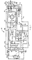
- Figure 1 is a schematic circuit diagram of an embodiment of an earth fault circuit breaker according to the invention;
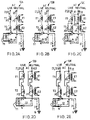
- Figures 2A to 2E are schematic circuit diagrams of five possible current-to-voltage converters suitable for use in the circuit breaker of Figure 1;
- Figures 3A to 3C are waveform diagrams showing the load and leakage currents detected by each current-to-voltage converter of Figures 2A to 2E; and
- Figures 4A and 4B are schematic circuit diagrams of two possible leakage current/voltage detectors suitable for use in the circuit breaker of Figure 1.
- Referring firstly to Figure 1 of the drawings, there is shown an earth
fault circuit breaker 10 embodying the invention, which is used in a circuit including aload 11 and an AC power supply (not shown). Thecircuit breaker 10 comprises a current-to-voltage converter 12, to which theload 11 is connected, for monitoring the load current including any earth fault current leaking from theload 11. A leakage current/voltage detector 13A is connected to the output of theconverter 12 for processing the converter output voltage to provide a resultant voltage for checking against a predetermined reference voltage to see if there is an earth leakage current. Thecircuit breaker 10 further includes a switching driver 14 arranged to disconnect theload 11 from the power supply in response to the presence of an earth leakage current. - Figures 2A to 2E show five alternative circuit designs to implement the current-to-
voltage converter 12, of which theconverter 12A of Figure 2A is firstly referred to. Theconverter 12A is formed by first and second transformers T1 and T2. The transformer T1 has first and second primary windings P1 and P2, and the transformer T2 has first and second primary windings P2 and P1. The corresponding primary windings P1 of the transformers T1 and T2 are identical, and so are the respective primary windings P2. The transformers T1 and T2 have corresponding identical secondary windings S. The first primary windings P1 and P2 of the transformers T1 and T2 are connected in series on the LIVE side of theload 11, and the second primary windings P2 and P1 on the load NEUTRAL side. It is to be understood that the transformers T1 and T2 have the same construction, but the connection of the primary windings P1 and P2 of one transformer T1 with respect to theload 11 is opposite to that for the other transformer T2. - In Figure 2A, the normal load current is designated by I2 and the leakage current caused by an earth fault appearing at the load is designated by I1. The load current I2 flows through both primary windings P1 and P2 of each transformer T1 or T2, but the leakage current I1 will only flow through, as shown, the first primary winding P1 of the transformer T1 and the first primary winding P2 of the transformer T2.
- The primary windings P1 and P2 of each transformer T1 or T2 have the same wire cross-sectional area, but the primary winding P1 has a relatively larger number of turns than the primary winding P2. The relative number of turns of the magnetically-coupled primary windings P1 and P2 is a factor determining the North/South polarity of the transformer T1 or T2. The configuration and arrangement of the primary windings P1 and P2 of the transformers T1 and T2 are designed such that the respective transformer inductances have the same magnitude but substantially in an anti-phase relationship. The load current I2 passing through the transformers T1 and T2 will cause substantially opposite North/South polarization effect in the primary windings P1 and P2. The North/South polarity of the magnetic field of each transformer T1 or T2 at any given time is determined by the resultant magnetic induction of one primary winding P1 or P2 over or below the other primary winding P2 or P1.
- Insofar as the load current I2 is concerned, this results in output emf's E1 and E2 at the corresponding secondary windings S of the transformers T1 and T2 having the same magnitude but 180° out of phase, as shown in Figure 3B. As the leakage current I1 flows only through the first primary windings P1 and P2 but not the second primary windings P2 and P1 of the transformers T1 and T2, respectively, the emf's E1 and E2 induced by the leakage current I1 at the transformer secondary windings S remain in phase, as shown in Figure 3A. The combined waveform of the emf E1 or E2 induced by the load and leakage currents I2 and I1 for each transformer T1 or T2 is shown in Figure 3C.
- Figures 4A and 4B of the drawings show two
alternative designs voltage comparator block 13B. - The leakage current/
voltage detector 13A is formed by a series pair of filtering capacitors C1 and C2 connected across the seconding windings S of the transformers T1 and T2, respectively, and by a resistor R3 connected in parallel with the pair of capacitors C1 and C2. As the capacitors C1 and C2 are connected in series, the filtered/ rectified output emf's E1 and E2 of the transformers T1 and T2 are superimposed together to produce a resultant voltage appearing across the resistor R3 for thevoltage comparator block 13B to process. It is to be understood that the two emf's induced by the load current I2 alone are substantially cancelled out by reason of their anti-phase relationship, resulting in the said resultant voltage representing a doubled value of the leakage current I1. - The
voltage comparator block 13B comprises an op-amp (operational amplifier)amplifier 15 for amplifying the resultant voltage given by the leakage current/voltage detector 13A and an op-amp comparator 16 for comparing the amplified resultant voltage with the reference voltage which is predetermined but adjustable by means of a variable resistor R4. The reference voltage corresponds to the maximum tolerable limit of an earth fault leakage current. Thus the triggering sensitivity of thecircuit breaker 10 responding to an earth fault is adjustable. The op-amp comparator 16 has at its output a diode D1 which conducts when the amplified resultant voltage exceeds the reference voltage. - The switching driver 14 is formed by a
solenoid 17 controlling a spring-biassed hingedsoft iron arm 18 and athyristor 19 controlling the operation of thesolenoid 17. The diode D1 of the op-amp comparator 16 is connected to the gate terminal of thethyristor 19 such that when the diode D1 conducts (in response to occurrence of leakage current I1) to trigger thethyristor 19 via its gate terminal, thethyristor 19 conducts to permit energizing of thesolenoid 17. Thesolenoid 17 then attracts to pivot the hingedarm 18 forwards to open a double-pole/double-throw switch 20 controlling the supply of power from the power supply to theload 11. - It is to be appreciated that the leakage current I1 may occur at any part of the load circuit, resulting in an unbalance or unsymmetrical state between the outputs of the transformers T1 and T2 and thereby producing a resultant voltage to trip the
switch 20 by means of the switching driver 14. - The
circuit breaker 10 further includes another voltage comparator block 21, incorporating an op-amp comparator 22, for detecting any over-current flowing through theload 11. A first input terminal of the op-amp comparator 22 is connected to the secondary winding S of the transformer T2 (or to that of the transformer T1) for picking up the output voltage of the transformer T2 (or transformer T1), said output voltage representing the magnitude of the load current I2. A second input terminal of the op-amp comparator 22 is connected to a variable resistor R5 provided across a DC operating voltage V for the entire circuitry and the local earth. The variable resistor R5 determines an adjustable threshold voltage for comparison by the op-amp comparator 22 with the voltage picked-up by the first input terminal. When the picked-up voltage exceeds the threshold voltage, the op-amp comparator 22 provides an output through a diode D2 connected to the gate terminal of thethyristor 19, thereby triggering thethyristor 19 to operate thesolenoid 17 to open theswitch 20 in order to disconnect theload 11 from the power supply. It is appreciated that by means of the variable resistor R5, the sensitivity of thecircuit breaker 10 responding to a load over-current is adjustable. - The
switch 20 has a pair of spring-biassedmoving switch contacts 25 and a elongate operating member 26 bearing at one end on theswitch contacts 25. The opposite end of the operating member 26 has a hook formation 27 normally engaging behind a fixedabutment 28 to hold theswitch 20 closed. The hingedarm 18 is pivoted by thesolenoid 17 to push the hook formation 27 off theabutment 28 to open theswitch 20. After the earth fault or over-current has been rectified, theswitch 20 is reset to re-connect theload 11 to the power supply by manually pushing the operating member 26 longitudinally back until the hook formation 27 engages behind theabutment 28 again, thereby re-closing theswitch 20. - The
circuit breaker 10 further includes a built-involtage regulator 23 for converting the mains AC voltage from the power supply into a DC voltage V for operating the entire circuitry. Theregulator 23 is formed by abridge rectifier 24, two capacitors C3 and C4, a resistor R6 and a zener diode Z1 connected together in a conventional manner to perform full wave rectification. - Referring more specifically to Figure 2B showing a second current-to-
voltage converter 12B which operates generally in the same manner as thefirst converter 12A. In thisconverter 12B, the primary windings P1 and P2 of both transformers T1 and T2 have the same number of turns but the primary windings P2 have a relatively larger wire cross-sectional area than the primary windings P1. Insofar as each pair of magnetically-coupled primary windings P1 and P2 is concerned, these windings interact to determine a certain phase shift for the transformer output emf E1 or E2 induced by the load current I2 flowing through both windings. The corresponding pairs of primary windings P1 and P2 of the transformers T1 and T2 are arranged such that the respective load current-induced transformer output emf's E1 and E2 are directly 180° out of phase. Insofar as the leakage current I1 is concerned, the corresponding induced transformer output emf's E1 and E2 remain in phase as the leakage current I1 only flows through the first primary windings but not the second primary windings of the transformers T1 and T2. - More specific reference is now made to Figure 2C, showing a third current-to-
voltage converter 12C which again operates generally in the same manner as thefirst converter 12A. All the four primary windings P1 and P2 of the transformers T1 and T2 have the same wire cross-sectional area and the same number of turns, but a resistor R1 or R2 is connected in parallel with each primary winding P2 to determine the required phase shift for the transformer output emf's E1 and E2. - Figures 2D and 2E show two other alternative current-to-
voltage converters 12D and 12E which are very similar to the first andsecond converters - The invention has been given by way of example only, and various other modifications of and/or alterations to the described embodiment may be made by persons skilled in the art without departing from the scope of the invention as specified in the appended claims.
Claims (12)
- An earth fault circuit breaker for use in a circuit including an AC power supply and a load, which circuit breaker comprises a current-to-voltage converter having two transformers for monitoring the current before and after flowing through the load, a leakage current/voltage detector for processing the outputs of the transformers to produce a resultant voltage, a voltage comparator for comparing the said resultant voltage with a predetermined reference voltage to determine if there is a difference between the two transformer outputs, which is caused by an earth fault appearing at the load, and a switching circuit for disconnecting the load from the power supply in response to such a difference between the two transformer outputs exceeding the predetermined reference voltage, wherein each transformer has first and second primary windings arranged to be connected to opposite sides of the load and the two transformers are arranged to provide outputs at their respective secondary windings, corresponding to the normal load current, in a substantially anti-phase relationship.
- An earth fault circuit breaker for use in a circuit including an AC power supply and a load, which circuit breaker comprises a current-to-voltage converter having two transformers for monitoring the current before and after flowing through the load, a voltage comparator for comparing the corresponding outputs of the transformers, and a switching circuit for disconnecting the load from the power supply in response to a difference between the two transformer outputs, which is caused by an earth fault appearing at the load, exceeding a predetermined reference voltage, wherein each transformer has first and second primary windings arranged to be connected to opposite sides of the load and the two transformers are arranged to provide outputs at their respective secondary windings, corresponding to the normal load current, in a substantially anti-phase relationship.
- An earth fault circuit breaker as claimed in claim 1 or claim 2, wherein the two transformers have substantially the same construction.
- An earth fault circuit breaker as claimed in any one of claims 1 to 3, wherein the corresponding first primary windings of the transformers are connected together in series and the corresponding second primary windings in series.
- An earth fault circuit breaker as claimed in any one of claims 1 to 3, wherein the corresponding first primary windings of the transformers are connected together in parallel and the corresponding second primary windings in parallel.
- An earth fault circuit breaker as claimed in any one of the preceding claims, wherein the first and second primary windings of each transformer have substantially the same wire cross-sectional area but different numbers of turns in order to render the transformer output at its secondary winding in a substantially anti-phase relationship with that of the other transformer.
- An earth fault circuit breaker as claimed in any one of claims 1 to 5, wherein the first and second primary windings of each transformer have substantially the same number of turns but different wire cross-sectional areas in order to render the transformer output at its secondary winding in a substantially anti-phase relationship with that of the other transformer.
- An earth fault circuit breaker as claimed in any one of claims 1 to 5, wherein the first and second primary windings of each transformer have substantially the same wire cross-sectional area and number of turns but one is connected in parallel with a resistor in order to render the transformer output at its secondary winding in a substantially anti-phase relationship with that of the other transformer.
- An earth fault circuit breaker as claimed in any one of the preceding claims, wherein the predetermined reference voltage is adjustable in order to adjust the sensitivity of the circuit breaker responding to an earth fault.
- An earth fault circuit breaker as claimed in any one of the preceding claims, further comprising another voltage comparator for comparing the output of either one of said transformers appearing at its secondary winding with a predetermined threshold voltage, exceeding which the switching circuit is to operate in order to avoid an over-current flowing through the load.
- An earth fault circuit breaker as claimed in claim 10, wherein the predetermined threshold voltage of the said another voltage comparator is adjustable in order to adjust the sensitivity of the circuit breaker responding to such an over-current.
- An earth fault circuit breaker substantially as hereinbefore described with reference to any one or more of Figures 1 to 4 of the accompanying drawings.
Applications Claiming Priority (2)
| Application Number | Priority Date | Filing Date | Title |
|---|---|---|---|
| GB9312284 | 1993-06-15 | ||
| GB9312284A GB2279189A (en) | 1993-06-15 | 1993-06-15 | Earth fault circuit breaker |
Publications (2)
| Publication Number | Publication Date |
|---|---|
| EP0634826A1 true EP0634826A1 (en) | 1995-01-18 |
| EP0634826B1 EP0634826B1 (en) | 1998-09-02 |
Family
ID=10737164
Family Applications (1)
| Application Number | Title | Priority Date | Filing Date |
|---|---|---|---|
| EP94304341A Expired - Lifetime EP0634826B1 (en) | 1993-06-15 | 1994-06-15 | Earth fault circuit breaker |
Country Status (10)
| Country | Link |
|---|---|
| US (1) | US5559657A (en) |
| EP (1) | EP0634826B1 (en) |
| JP (1) | JPH07143669A (en) |
| KR (1) | KR950001816A (en) |
| CN (1) | CN1043392C (en) |
| AT (1) | ATE170676T1 (en) |
| CA (1) | CA2125799A1 (en) |
| DE (1) | DE69412938T2 (en) |
| GB (1) | GB2279189A (en) |
| TW (1) | TW223713B (en) |
Families Citing this family (24)
| Publication number | Priority date | Publication date | Assignee | Title |
|---|---|---|---|---|
| WO1996031931A1 (en) * | 1995-04-07 | 1996-10-10 | Norcel Limited | A.c. power cut-off device |
| GB2303005A (en) * | 1995-07-01 | 1997-02-05 | Ampy Automation Digilog | Controlling electrical supply to a consumer |
| GB2303980B (en) * | 1995-08-02 | 1997-09-10 | Sheir Chun Lam | Circuit breaker |
| FR2778033B1 (en) * | 1998-04-28 | 2000-07-13 | Legrand Sa | CURRENT LEVEL DETECTION DEVICE FOR PROTECTING A CIRCUIT AGAINST AC CURRENT |
| US6388451B1 (en) | 2000-08-16 | 2002-05-14 | Ford Global Technologies, Inc. | Leakage current cancellation device |
| JP2002233045A (en) | 2001-02-02 | 2002-08-16 | Canon Inc | Ground detecting device for photovoltaic power generation system and method |
| AU2002950581A0 (en) * | 2002-08-02 | 2002-09-12 | Wayne Callen | Electrical safety circuit |
| KR100445339B1 (en) * | 2002-11-01 | 2004-08-18 | 한국수력원자력 주식회사 | ground detect apparatus of differential current for DC signal line and method theroof |
| CN100444489C (en) * | 2003-02-03 | 2008-12-17 | 立维腾制造有限公司 | Circuit interrupting device with single throw, double mode button for test-reset function |
| CN100433481C (en) * | 2005-07-18 | 2008-11-12 | 吴少华 | Earth fault breaker |
| US7920037B2 (en) * | 2008-05-08 | 2011-04-05 | Cooper Technologies Company | Fault interrupter and load break switch |
| CN102610441B (en) * | 2012-03-22 | 2014-07-09 | 通达科技国际有限公司 | Remote-control interactive power switch |
| GB2505016A (en) * | 2012-08-16 | 2014-02-19 | Technology Logic Internat Ltd | Remote-control interactive power switch |
| US20160276120A1 (en) * | 2014-03-21 | 2016-09-22 | General Electric Company | Systems and methods for energy saving contactor |
| KR101631633B1 (en) | 2014-07-15 | 2016-06-17 | 엘에스산전 주식회사 | Fault current detecting circuit |
| US10361051B2 (en) | 2014-11-06 | 2019-07-23 | Rockwell Automation Technologies, Inc. | Single pole, single current path switching system and method |
| US9806642B2 (en) | 2014-11-06 | 2017-10-31 | Rockwell Automation Technologies, Inc. | Modular multiple single-pole electromagnetic switching system and method |
| US9722513B2 (en) | 2014-11-06 | 2017-08-01 | Rockwell Automation Technologies, Inc. | Torque-based stepwise motor starting |
| US9748873B2 (en) | 2014-11-06 | 2017-08-29 | Rockwell Automation Technologies, Inc. | 5-pole based wye-delta motor starting system and method |
| US9806641B2 (en) | 2014-11-06 | 2017-10-31 | Rockwell Automation Technologies, Inc. | Detection of electric motor short circuits |
| US10074497B2 (en) | 2014-11-06 | 2018-09-11 | Rockwell Automation Technologies, Inc. | Operator coil parameter based electromagnetic switching |
| US10141143B2 (en) | 2014-11-06 | 2018-11-27 | Rockwell Automation Technologies, Inc. | Wear-balanced electromagnetic motor control switching |
| US10393809B2 (en) | 2014-11-06 | 2019-08-27 | Rockwell Automation Technologies, Inc. | Intelligent timed electromagnetic switching |
| CN109478777B (en) * | 2016-03-14 | 2020-05-22 | 香港理工大学 | Control circuit and high-frequency circuit breaker |
Citations (7)
| Publication number | Priority date | Publication date | Assignee | Title |
|---|---|---|---|---|
| US3866093A (en) * | 1972-09-18 | 1975-02-11 | Norbert L Kusters | Low leakage electrical power input circuit for electromedical and other similar apparatus |
| DE2611674A1 (en) * | 1976-03-19 | 1977-09-22 | Guenter Reichensperger | Protective circuit breaker system - has electronic earth resistance monitor and electronic faulty current monitor to control load circuit breaking |
| GB1532084A (en) * | 1975-03-19 | 1978-11-15 | Bbc Brown Boveri & Cie | Earth leakage circuit breaker |
| GB2019677A (en) * | 1978-04-19 | 1979-10-31 | Westinghouse Electric Corp | People protecting ground fault circuit breaker utilizing wveform characteristics |
| US4255773A (en) * | 1977-03-24 | 1981-03-10 | Jabbal Harbhajan S | Ground fault interruptor |
| US4580186A (en) * | 1983-07-15 | 1986-04-01 | Parker Douglas F | Grounding and ground fault detection circuits |
| US5173831A (en) * | 1991-08-19 | 1992-12-22 | Sammartano Arthur J | Neutral line circuit interrupter |
Family Cites Families (3)
| Publication number | Priority date | Publication date | Assignee | Title |
|---|---|---|---|---|
| CH529462A (en) * | 1970-08-29 | 1972-10-15 | Siemens Ag | Residual current circuit breaker |
| US3864581A (en) * | 1973-01-22 | 1975-02-04 | Varahur Srinivas Satyanarayana | Shock prevention device |
| US5177657A (en) * | 1991-05-16 | 1993-01-05 | Felchar Manufacturing Corporation | Ground fault interruptor circuit with electronic latch |
-
1993
- 1993-06-15 GB GB9312284A patent/GB2279189A/en not_active Withdrawn
- 1993-06-29 TW TW082105181A patent/TW223713B/en active
-
1994
- 1994-06-14 CA CA002125799A patent/CA2125799A1/en not_active Abandoned
- 1994-06-15 JP JP6133187A patent/JPH07143669A/en active Pending
- 1994-06-15 DE DE69412938T patent/DE69412938T2/en not_active Expired - Fee Related
- 1994-06-15 US US08/261,894 patent/US5559657A/en not_active Expired - Fee Related
- 1994-06-15 KR KR1019940013537A patent/KR950001816A/en not_active Application Discontinuation
- 1994-06-15 CN CN94107603A patent/CN1043392C/en not_active Expired - Fee Related
- 1994-06-15 EP EP94304341A patent/EP0634826B1/en not_active Expired - Lifetime
- 1994-06-15 AT AT94304341T patent/ATE170676T1/en not_active IP Right Cessation
Patent Citations (7)
| Publication number | Priority date | Publication date | Assignee | Title |
|---|---|---|---|---|
| US3866093A (en) * | 1972-09-18 | 1975-02-11 | Norbert L Kusters | Low leakage electrical power input circuit for electromedical and other similar apparatus |
| GB1532084A (en) * | 1975-03-19 | 1978-11-15 | Bbc Brown Boveri & Cie | Earth leakage circuit breaker |
| DE2611674A1 (en) * | 1976-03-19 | 1977-09-22 | Guenter Reichensperger | Protective circuit breaker system - has electronic earth resistance monitor and electronic faulty current monitor to control load circuit breaking |
| US4255773A (en) * | 1977-03-24 | 1981-03-10 | Jabbal Harbhajan S | Ground fault interruptor |
| GB2019677A (en) * | 1978-04-19 | 1979-10-31 | Westinghouse Electric Corp | People protecting ground fault circuit breaker utilizing wveform characteristics |
| US4580186A (en) * | 1983-07-15 | 1986-04-01 | Parker Douglas F | Grounding and ground fault detection circuits |
| US5173831A (en) * | 1991-08-19 | 1992-12-22 | Sammartano Arthur J | Neutral line circuit interrupter |
Also Published As
| Publication number | Publication date |
|---|---|
| EP0634826B1 (en) | 1998-09-02 |
| GB9312284D0 (en) | 1993-07-28 |
| JPH07143669A (en) | 1995-06-02 |
| GB2279189A (en) | 1994-12-21 |
| CN1043392C (en) | 1999-05-12 |
| TW223713B (en) | 1994-05-11 |
| US5559657A (en) | 1996-09-24 |
| CA2125799A1 (en) | 1994-12-16 |
| KR950001816A (en) | 1995-01-04 |
| CN1106568A (en) | 1995-08-09 |
| DE69412938T2 (en) | 1999-05-12 |
| DE69412938D1 (en) | 1998-10-08 |
| ATE170676T1 (en) | 1998-09-15 |
Similar Documents
| Publication | Publication Date | Title |
|---|---|---|
| US5559657A (en) | Earth fault circuit breaker | |
| US4159499A (en) | Ground fault detection and protection circuit | |
| US4685022A (en) | Ground fault circuit interrupter capable of deriving energy from ground fault current in order to achieve circuit interruption in the presence of a reduced supply voltage | |
| US5745322A (en) | Circuit protection arrangements using ground fault interrupter for overcurrent and overvoltage protection | |
| US7304829B2 (en) | Apparatus and method for filtering current sensor output signals | |
| US4034269A (en) | Protective relay circuits | |
| KR101759598B1 (en) | Digital relay with sensibility of secondary circuit opening | |
| CA2064027C (en) | Ground fault circuit interrupter | |
| US5627712A (en) | Transformer differential relay | |
| AU754350B2 (en) | Circuit breaker | |
| US3976918A (en) | False triggering protection for ground fault sensor | |
| US4279007A (en) | Single-phase fault detecting circuit breaker | |
| JPH0630579A (en) | Current detecting circuit | |
| AU2019447727B2 (en) | Electric line (L) protection device for detecting a leakage fault, a short-circuit, fault, an overcurrent fault and an arc fault | |
| IE850214L (en) | Residual current device | |
| KR0119778Y1 (en) | Leakage current circuit breaker | |
| JP2002335625A (en) | Relay method for protecting transformer | |
| RU1818657C (en) | Method for protection of phase-regulating transformer | |
| JPH066673Y2 (en) | AA leakage breaker with neutral phase protection | |
| JPS631559Y2 (en) | ||
| JPH05260760A (en) | Open-phase detection circuit of invertor | |
| JPH04248316A (en) | Overcurrent protector for power converter | |
| Elmore | Basic Relay Units | |
| JPS6224889B2 (en) | ||
| JPS63305716A (en) | Circuit breaker |
Legal Events
| Date | Code | Title | Description |
|---|---|---|---|
| PUAI | Public reference made under article 153(3) epc to a published international application that has entered the european phase |
Free format text: ORIGINAL CODE: 0009012 |
|
| AK | Designated contracting states |
Kind code of ref document: A1 Designated state(s): AT BE CH DE DK ES FR GB GR IE IT LI LU MC NL PT SE |
|
| RAX | Requested extension states of the european patent have changed |
Free format text: SI |
|
| 17P | Request for examination filed |
Effective date: 19950704 |
|
| 17Q | First examination report despatched |
Effective date: 19960827 |
|
| GRAG | Despatch of communication of intention to grant |
Free format text: ORIGINAL CODE: EPIDOS AGRA |
|
| GRAG | Despatch of communication of intention to grant |
Free format text: ORIGINAL CODE: EPIDOS AGRA |
|
| GRAH | Despatch of communication of intention to grant a patent |
Free format text: ORIGINAL CODE: EPIDOS IGRA |
|
| GRAH | Despatch of communication of intention to grant a patent |
Free format text: ORIGINAL CODE: EPIDOS IGRA |
|
| GRAA | (expected) grant |
Free format text: ORIGINAL CODE: 0009210 |
|
| AK | Designated contracting states |
Kind code of ref document: B1 Designated state(s): AT BE CH DE DK ES FR GB GR IE IT LI LU MC NL PT SE |
|
| PG25 | Lapsed in a contracting state [announced via postgrant information from national office to epo] |
Ref country code: GR Free format text: LAPSE BECAUSE OF NON-PAYMENT OF DUE FEES Effective date: 19980902 Ref country code: ES Free format text: THE PATENT HAS BEEN ANNULLED BY A DECISION OF A NATIONAL AUTHORITY Effective date: 19980902 Ref country code: BE Free format text: LAPSE BECAUSE OF FAILURE TO SUBMIT A TRANSLATION OF THE DESCRIPTION OR TO PAY THE FEE WITHIN THE PRESCRIBED TIME-LIMIT Effective date: 19980902 Ref country code: AT Free format text: LAPSE BECAUSE OF FAILURE TO SUBMIT A TRANSLATION OF THE DESCRIPTION OR TO PAY THE FEE WITHIN THE PRESCRIBED TIME-LIMIT Effective date: 19980902 |
|
| REF | Corresponds to: |
Ref document number: 170676 Country of ref document: AT Date of ref document: 19980915 Kind code of ref document: T |
|
| REG | Reference to a national code |
Ref country code: CH Ref legal event code: EP |
|
| REF | Corresponds to: |
Ref document number: 69412938 Country of ref document: DE Date of ref document: 19981008 |
|
| RAP2 | Party data changed (patent owner data changed or rights of a patent transferred) |
Owner name: LANDT LICENSING COMPANY LIMITED |
|
| NLT2 | Nl: modifications (of names), taken from the european patent patent bulletin |
Owner name: LANDT LICENSING COMPANY LIMITED |
|
| PG25 | Lapsed in a contracting state [announced via postgrant information from national office to epo] |
Ref country code: SE Free format text: LAPSE BECAUSE OF FAILURE TO SUBMIT A TRANSLATION OF THE DESCRIPTION OR TO PAY THE FEE WITHIN THE PRESCRIBED TIME-LIMIT Effective date: 19981202 Ref country code: PT Free format text: LAPSE BECAUSE OF FAILURE TO SUBMIT A TRANSLATION OF THE DESCRIPTION OR TO PAY THE FEE WITHIN THE PRESCRIBED TIME-LIMIT Effective date: 19981202 Ref country code: DK Free format text: LAPSE BECAUSE OF FAILURE TO SUBMIT A TRANSLATION OF THE DESCRIPTION OR TO PAY THE FEE WITHIN THE PRESCRIBED TIME-LIMIT Effective date: 19981202 |
|
| REG | Reference to a national code |
Ref country code: IE Ref legal event code: FG4D |
|
| ET | Fr: translation filed | ||
| REG | Reference to a national code |
Ref country code: CH Ref legal event code: NV Representative=s name: RITSCHER & SEIFERT |
|
| NLXE | Nl: other communications concerning ep-patents (part 3 heading xe) |
Free format text: PAT. BUL. 01/99 PAGE 52: CORR.: LANDT LICENSING COMPANY LIMITED |
|
| PG25 | Lapsed in a contracting state [announced via postgrant information from national office to epo] |
Ref country code: LU Free format text: LAPSE BECAUSE OF NON-PAYMENT OF DUE FEES Effective date: 19990615 Ref country code: IE Free format text: LAPSE BECAUSE OF NON-PAYMENT OF DUE FEES Effective date: 19990615 |
|
| PG25 | Lapsed in a contracting state [announced via postgrant information from national office to epo] |
Ref country code: LI Free format text: LAPSE BECAUSE OF NON-PAYMENT OF DUE FEES Effective date: 19990630 Ref country code: CH Free format text: LAPSE BECAUSE OF NON-PAYMENT OF DUE FEES Effective date: 19990630 |
|
| PLBE | No opposition filed within time limit |
Free format text: ORIGINAL CODE: 0009261 |
|
| STAA | Information on the status of an ep patent application or granted ep patent |
Free format text: STATUS: NO OPPOSITION FILED WITHIN TIME LIMIT |
|
| 26N | No opposition filed | ||
| PG25 | Lapsed in a contracting state [announced via postgrant information from national office to epo] |
Ref country code: MC Free format text: LAPSE BECAUSE OF NON-PAYMENT OF DUE FEES Effective date: 19991231 |
|
| REG | Reference to a national code |
Ref country code: CH Ref legal event code: PL |
|
| REG | Reference to a national code |
Ref country code: IE Ref legal event code: MM4A |
|
| PGFP | Annual fee paid to national office [announced via postgrant information from national office to epo] |
Ref country code: FR Payment date: 20000612 Year of fee payment: 7 |
|
| PGFP | Annual fee paid to national office [announced via postgrant information from national office to epo] |
Ref country code: DE Payment date: 20000614 Year of fee payment: 7 |
|
| PGFP | Annual fee paid to national office [announced via postgrant information from national office to epo] |
Ref country code: NL Payment date: 20000629 Year of fee payment: 7 |
|
| REG | Reference to a national code |
Ref country code: GB Ref legal event code: 732E |
|
| PG25 | Lapsed in a contracting state [announced via postgrant information from national office to epo] |
Ref country code: NL Free format text: LAPSE BECAUSE OF NON-PAYMENT OF DUE FEES Effective date: 20020101 |
|
| REG | Reference to a national code |
Ref country code: GB Ref legal event code: IF02 |
|
| PG25 | Lapsed in a contracting state [announced via postgrant information from national office to epo] |
Ref country code: FR Free format text: LAPSE BECAUSE OF NON-PAYMENT OF DUE FEES Effective date: 20020228 |
|
| NLV4 | Nl: lapsed or anulled due to non-payment of the annual fee |
Effective date: 20020101 |
|
| PG25 | Lapsed in a contracting state [announced via postgrant information from national office to epo] |
Ref country code: DE Free format text: LAPSE BECAUSE OF NON-PAYMENT OF DUE FEES Effective date: 20020403 |
|
| PGFP | Annual fee paid to national office [announced via postgrant information from national office to epo] |
Ref country code: GB Payment date: 20020708 Year of fee payment: 9 |
|
| PG25 | Lapsed in a contracting state [announced via postgrant information from national office to epo] |
Ref country code: GB Free format text: LAPSE BECAUSE OF NON-PAYMENT OF DUE FEES Effective date: 20030615 |
|
| GBPC | Gb: european patent ceased through non-payment of renewal fee |
Effective date: 20030615 |
|
| PG25 | Lapsed in a contracting state [announced via postgrant information from national office to epo] |
Ref country code: IT Free format text: LAPSE BECAUSE OF NON-PAYMENT OF DUE FEES Effective date: 20050615 |