EP0634820B1 - Connecting device for electric components - Google Patents
Connecting device for electric components Download PDFInfo
- Publication number
- EP0634820B1 EP0634820B1 EP93830344A EP93830344A EP0634820B1 EP 0634820 B1 EP0634820 B1 EP 0634820B1 EP 93830344 A EP93830344 A EP 93830344A EP 93830344 A EP93830344 A EP 93830344A EP 0634820 B1 EP0634820 B1 EP 0634820B1
- Authority
- EP
- European Patent Office
- Prior art keywords
- conductors
- electric
- connecting elements
- anchoring
- electric connecting
- Prior art date
- Legal status (The legal status is an assumption and is not a legal conclusion. Google has not performed a legal analysis and makes no representation as to the accuracy of the status listed.)
- Expired - Lifetime
Links
- 239000004020 conductor Substances 0.000 claims abstract description 63
- 238000004873 anchoring Methods 0.000 claims abstract description 36
- 230000008878 coupling Effects 0.000 claims abstract description 26
- 238000010168 coupling process Methods 0.000 claims abstract description 26
- 238000005859 coupling reaction Methods 0.000 claims abstract description 26
- 238000003780 insertion Methods 0.000 claims description 8
- 230000037431 insertion Effects 0.000 claims description 8
- 239000002775 capsule Substances 0.000 claims description 4
- 230000000694 effects Effects 0.000 claims description 4
- 230000001747 exhibiting effect Effects 0.000 claims description 3
- 238000000034 method Methods 0.000 description 3
- 239000000463 material Substances 0.000 description 2
- 229920003023 plastic Polymers 0.000 description 2
- 238000003466 welding Methods 0.000 description 2
- RYGMFSIKBFXOCR-UHFFFAOYSA-N Copper Chemical compound [Cu] RYGMFSIKBFXOCR-UHFFFAOYSA-N 0.000 description 1
- 230000009471 action Effects 0.000 description 1
- 238000005452 bending Methods 0.000 description 1
- 239000011248 coating agent Substances 0.000 description 1
- 238000000576 coating method Methods 0.000 description 1
- 229910052802 copper Inorganic materials 0.000 description 1
- 239000010949 copper Substances 0.000 description 1
- 238000012986 modification Methods 0.000 description 1
- 230000004048 modification Effects 0.000 description 1
- 230000008569 process Effects 0.000 description 1
- 230000009467 reduction Effects 0.000 description 1
- 230000000630 rising effect Effects 0.000 description 1
- 230000003245 working effect Effects 0.000 description 1
Images
Classifications
-
- H—ELECTRICITY
- H01—ELECTRIC ELEMENTS
- H01R—ELECTRICALLY-CONDUCTIVE CONNECTIONS; STRUCTURAL ASSOCIATIONS OF A PLURALITY OF MUTUALLY-INSULATED ELECTRICAL CONNECTING ELEMENTS; COUPLING DEVICES; CURRENT COLLECTORS
- H01R33/00—Coupling devices specially adapted for supporting apparatus and having one part acting as a holder providing support and electrical connection via a counterpart which is structurally associated with the apparatus, e.g. lamp holders; Separate parts thereof
- H01R33/05—Two-pole devices
- H01R33/06—Two-pole devices with two current-carrying pins, blades or analogous contacts, having their axes parallel to each other
-
- H—ELECTRICITY
- H01—ELECTRIC ELEMENTS
- H01R—ELECTRICALLY-CONDUCTIVE CONNECTIONS; STRUCTURAL ASSOCIATIONS OF A PLURALITY OF MUTUALLY-INSULATED ELECTRICAL CONNECTING ELEMENTS; COUPLING DEVICES; CURRENT COLLECTORS
- H01R4/00—Electrically-conductive connections between two or more conductive members in direct contact, i.e. touching one another; Means for effecting or maintaining such contact; Electrically-conductive connections having two or more spaced connecting locations for conductors and using contact members penetrating insulation
- H01R4/24—Connections using contact members penetrating or cutting insulation or cable strands
- H01R4/2404—Connections using contact members penetrating or cutting insulation or cable strands the contact members having teeth, prongs, pins or needles penetrating the insulation
- H01R4/2406—Connections using contact members penetrating or cutting insulation or cable strands the contact members having teeth, prongs, pins or needles penetrating the insulation having needles or pins
Definitions
- the present invention relates to a connecting device for electric components, of the type comprising, the features defined in the preamble of claim 1.
- the connecting device aims at electrically connecting bulb microlamps, of the type used for signal lights in electrical apparatus and the like.
- the device in question can also be conceived for uses different from the described one.
- connection of electric and/or electronic components to respective electric conductors can be presently made following different modalities.
- the electric or electronic component be equipped with appropriate terminals to which the ends of the respective conductors are secured by welding, upon removal of the insulating sheath coating said ends.
- suitable connectors may be associated with the electric conductor ends through a mere clasping operation, said connectors being adapted to be engaged by forced fitting on corresponding terminals associated with the electric or electronic component to be connected.
- connecting devices enabling the connection of all conductors associated with an electric or electronic component to be carried out simultaneously in a single operation, without requiring removal of the insulating sheath from the ends of the individual conductors.
- These devices essentially comprise one connecting portion usually made of plastic material in which a plurality of anchoring seats is formed, each being designed to house the terminal end of a respective conductor.
- a second connecting portion that, by engagement means usually of the snug-fitting type, lends itself to be fastened to the first portion in a predetermined operating condition.
- the second connecting portion rigidly carries a plurality of electric connecting elements that are suitably connected to the electric or electronic component before or after assembling of the connecting device.
- Each of these electric connecting elements having substantially a plate-like structure exhibits a substantially fork-shaped active portion that, on engagement of the first and second connecting portions in the operating condition, exerts pressure against the end of one of the conductors so as to cut the insulating sheath at diametrically opposite locations, coming thereby into contact with the conductor core consisting of strands of conductive material.
- the electric connecting elements used in this type of connecting devices have a transverse extension necessarily greater than the diametrical sizes of the conductors. Therefore, when connection of a plurality of conductors disposed consecutively in side by side relation is to be carried out, it is necessary to arrange the individual electric connecting elements in several rows conveniently spaced apart from each other; as a result, the connecting device will be very bulky.
- Document FR n. 2 682 226 discloses a connecting device for electric components having a first portion, shaped as a lamp holder, exibiting anchoring seats for electric conductors and electric connecting elements each of which is shaped as a piercing point protruding from a supporting block engaged in a seat defined in the first portion.
- the electric connecting elements extend throgh the path of the conductor cable engaged in the anchoring seats, so that the conductors may be inserted into the anchoring seats and pierced by the electric connecting elements for achieving an electric connection with a lamp associated to the first portion.
- a second portion is engageable to the first portion for tightly closing the housing of the conductors and electric connecting elements.
- Such a second portion exhibits retaining recesses each engaging the end of a respective electric connecting elements.
- the object of the present invention is substantially to overcome the drawbacks of the known art by providing a connecting device that not only enables the electric connection to be carried out on the ends of insulated conductors in a very practical and easy manner, but also ensures an excellent resistance to the tractive efforts transmitted by the conductors and in addition has very reduced sizes, is not very expensive and can be easily mounted.
- a connecting device for electric components in accordance with the invention has been generally identified by reference numeral 1.
- the connecting device 1 is associated with a bulb microlamp 2 known per se and conventional, for enabling connection of said lamp with a pair of conductors 3 each of which conventionally has a core 4 consisting of strands made of copper or other conductive material, surrounded by an insulating sheath 5.
- the device 1 comprises one connecting portion generally denoted by 6, exhibiting one or more anchoring seats 7 each designed to house a terminal end 3a of one of the electric conductors 3.
- each of the anchoring seats 7 matches that of the terminal end 3a of the corresponding conductor 3 so that each seat completely encloses said terminal end and is in contact relationship with the outer surfaces thereof.
- the anchoring seats 7 have a diameter only marginally greater than the outer diameter of the insulating sheaths of the conductors 3, for the purposes to be clarified in the following.
- a second connecting portion generally identified by 10, carrying one or more electric connecting elements 11 each arranged to electrically connect the core 4 of one of the conductors 3 to the microlamp 2 or other electric components with which the device 1 is associated.
- the second connecting portion 10 comprises a supporting block 12 in which said electric connecting elements 11 are engaged by a snug-fitting operation carried out in known manner.
- This supporting block is rigidly housed, by snug-fitting for example, within a containing capsule 13 preferably made of transparent plastic material, inside which the microlamp 2 is located.
- the supporting block 12 may also engage, in a manner known per se, one or more electric resistors 15 operatively interposed between the electric connecting elements 11 and the bulb microlamp 2.
- each of the electric connecting elements 11 is shaped as a piercing point substantially oriented in a fitting direction perpendicularly intersecting the longitudinal axis of the respective anchoring seat 7, to the ends better clarified in the following.
- each electric connecting element 11 has a substantially plate-like structure, lying in a plane perpendicular to the longitudinal axis of the respective anchoring seat 7 having a wedge-shaped profile defined by two side edges 11b converging away from the supporting block 12 as far as they meet at one end 11a of the electric connecting element.
- An engagement means 16 is associated with the first and second connecting portions 6, 10 and arranged to fix the mutual positioning of said connecting portions in an operating condition in which, as better described in the following, the electric connecting elements 11 operatively act in contact relationship on the cores 4 of the respective conductors 3.
- said engagement means 16 essentially comprises a coupling bush 17 and a guide collar 18 associated with the first and second connecting portions 6, 10 respectively and susceptible of being coaxially engaged with each other by mutual sliding parallelly to the fitting direction of each electric connecting element 11.
- the guide collar 18 is formed with one end of said containing capsule 13 and the coupling bush 17 projects perpendicularly from the perimetric edge of the base wall 9 of the first connecting portion 6, encircling said central small base 8.
- an annular groove 19 is defined between the central small base 8 and coupling bush 17, the end of the guide collar 18 being housed, in the operating condition, in said groove.
- first and second side ports 20, 21, respectively that are located in alignment with the anchoring seats 7 and designed to be passed through by the conductors 3 emerging from the anchoring seats.
- the first side ports 20 also extend close to the base wall 9 of the first connecting portion 6, so that the conductors 3 may be oriented at least in a direction substantially parallel to the fitting direction, as shown by chain line in Fig. 2.
- the presence of hooking elements 22 is also provided and they are associated with the base wall 9 for holding the conductors 3 according to an orientation opposite to the respective terminal ends 3a introduced into the anchoring seats 7.
- the engagement between the guide collar 18 and coupling bush 17 enables the mutual movement of the first and second connecting portions 6, 10 from a preparatory arrangement condition in which they are mutually spaced apart as shown in chain line in Fig. 3, to said operating condition in which the first and second connecting portions are disposed close to each other, as shown in solid line.
- the ends 11a of the electric connecting elements 11 are disengaged from the respective anchoring seats 7 so that the terminal ends 3a belonging to the corresponding conductors 3 can be fitted therein.
- the ends 11a of the electric connecting elements 11 are located in respective access openings 23 defined in the central small base 8 of the first connecting portion 6.
- the electric connecting elements 11 diametrically cross the terminal ends 3a of the corresponding conductors 3 piercing the insulating layer or sheath 5 and dividing the strands forming the core 4 into two groups for engaging their ends 11a in corresponding retaining recesses 24 defined in the base wall 9, within each anchoring seat 7, on the side opposite to the respective access opening 23.
- the terminal ends undergo a deformation involving a side expansion counteracted by the inner surfaces of the corresponding anchoring seats 7 that, as previously described, are in a contact relationship on the insulating sheaths 5 already in the preparatory arrangement condition. This situation further ensures the close contact and electric continuity between the cores 4 of the conductors 3 and the electric connecting elements 11.
- At least one first fitting lug 25 and at least one first coupling slot 26 are provided to be associated with the engagement means 16 and they are formed on the guide collar 18 and coupling bush 17 respectively, so as to be mutually engaged by snap fitting, as clearly shown in Fig. 3. More particularly, in the embodiment shown the presence of a pair of said first fitting lugs 25 and coupling slots 26 is provided.
- Each first fitting lug 25 has an inclined slide side 25a at which forced sliding of the coupling bush 17 moving towards the operating condition, occurs.
- the inclined side 25a is followed by an abutment shoulder 25b designed to act on an edge of the coupling slot 26 when the fitting lug 25 snaps therein on reaching of the operating condition.
- the guide collar 18 is at least one second fitting lug 27 suitably spaced apart from the first fitting lugs 25 with reference to the insertion direction. More particularly, the presence of a pair of said second fitting lugs 27 is provided and each of them engages one of the first coupling slots 26 for fixing the mutual positioning of the first and second connecting portions 6, 10 to the preparatory arrangement condition, in the same manner as described with reference to the first fitting lugs 25.
- This situation appears to be very advantageous for facilitating introduction of the terminal ends 3a of the conductors 3 into the respective anchoring seats 7, above all when the connecting operation is carried out by automated machines.
- At least one second coupling slot 28 be formed in the coupling bush 17.
- the device 1 is preassembled to the preparatory arrangement condition by a mere operation consisting in fitting the coupling bush 17 on the guide collar 18.
- the connecting operation for enabling current supply to the microlamp 2 only requires that the terminal ends 3a of the conductors 3 be introduced into the anchoring seats 7, stripping being unnecessary. Since the anchoring seats 7 are oriented parallel to each other, insertion of the conductors 3 can be easily carried out by a single operation.
- the only operation to be done is pushing the first connecting portion 6 to the operating condition for causing the simultaneous connection of the conductors 3 to the microlamp 2, as a result of the conductors themselves being passed through by the electric connecting elements 11.
- the present invention attains the intended purposes.
- the device in question is capable of ensuring an excellent connecting strength in terms of tractive efforts that may be imposed to the conductors 3.
- the use of electric connecting elements in the form of a piercing point enables the side dimensions of said electric connecting elements to be greatly reduced, which brings about an important reduction in the bulkiness of the whole device as compared to the devices of the known art, above all with reference to connections in which the conductors, connected side by side to each other through the respective insulating layers, form a single ribbon-like structure.
- the present invention enables arrangement in a single plane of as many electric connecting elements 11 as the conductors to be connected, unlike the solutions of the known art where due to the greater bulkiness of the electric connecting elements, their distribution in offset rows is required.
Landscapes
- Connections By Means Of Piercing Elements, Nuts, Or Screws (AREA)
- Coupling Device And Connection With Printed Circuit (AREA)
- Details Of Connecting Devices For Male And Female Coupling (AREA)
- Coils Or Transformers For Communication (AREA)
- Multi-Conductor Connections (AREA)
- Connector Housings Or Holding Contact Members (AREA)
- Apparatus For Radiation Diagnosis (AREA)
- Fixed Capacitors And Capacitor Manufacturing Machines (AREA)
- Discharge Heating (AREA)
- Connections Arranged To Contact A Plurality Of Conductors (AREA)
Abstract
Description
- The present invention relates to a connecting device for electric components, of the type comprising, the features defined in the preamble of claim 1.
- In the embodiment to which reference will be particularly made in the course of the present description the connecting device aims at electrically connecting bulb microlamps, of the type used for signal lights in electrical apparatus and the like. However it is understood that the device in question can also be conceived for uses different from the described one.
- It is known that connection of electric and/or electronic components to respective electric conductors can be presently made following different modalities.
- According to a first system it is essentially provided that the electric or electronic component be equipped with appropriate terminals to which the ends of the respective conductors are secured by welding, upon removal of the insulating sheath coating said ends.
- The execution of this method involves many difficulties above all with reference to small-sized and mass-produced electric or electronic components where the connection of the wires is required to be carried out in a completely automated manner and within a very short period of time.
- According to another known connecting method, suitable connectors may be associated with the electric conductor ends through a mere clasping operation, said connectors being adapted to be engaged by forced fitting on corresponding terminals associated with the electric or electronic component to be connected.
- This solution has undoubted advantages as compared to the execution of a welding, but suffers from some drawbacks too, such as the necessity of carrying out different workings for removing the insulating sheath from the conductor ends and fastening the connectors thereto.
- It is also to be noted that with the use of the above described connectors operations for engaging each conductor to the respective terminal take place independently of each other. This situation involves important technical difficulties when in automated processes such engagement operations must be carried out simultaneously for the purpose of reducing the working time.
- There are also connecting devices enabling the connection of all conductors associated with an electric or electronic component to be carried out simultaneously in a single operation, without requiring removal of the insulating sheath from the ends of the individual conductors.
- These devices essentially comprise one connecting portion usually made of plastic material in which a plurality of anchoring seats is formed, each being designed to house the terminal end of a respective conductor. Combined with the first connecting portion is a second connecting portion that, by engagement means usually of the snug-fitting type, lends itself to be fastened to the first portion in a predetermined operating condition.
- The second connecting portion rigidly carries a plurality of electric connecting elements that are suitably connected to the electric or electronic component before or after assembling of the connecting device. Each of these electric connecting elements having substantially a plate-like structure exhibits a substantially fork-shaped active portion that, on engagement of the first and second connecting portions in the operating condition, exerts pressure against the end of one of the conductors so as to cut the insulating sheath at diametrically opposite locations, coming thereby into contact with the conductor core consisting of strands of conductive material.
- It has been found however that also in the connecting devices of this type the resistance of the connection to tractive efforts carried out on the conductors is not completely satisfactory, even if important costs are involved. It may in fact happen that under the effect of tractive forces the insulating sheath cut off at the electric connecting element gets torn over the whole section thereof, the core formed of the conductive strands being consequently pulled away from the electric connecting element itself. In other cases it may happen that, still under the effect of tractive efforts transmitted from the conductors, one or more of the electric connecting elements bend at their active portions and disengage from the conductors themselves.
- It is also to be pointed out that the electric connecting elements used in this type of connecting devices have a transverse extension necessarily greater than the diametrical sizes of the conductors. Therefore, when connection of a plurality of conductors disposed consecutively in side by side relation is to be carried out, it is necessary to arrange the individual electric connecting elements in several rows conveniently spaced apart from each other; as a result, the connecting device will be very bulky.
- Document FR n. 2 682 226 discloses a connecting device for electric components having a first portion, shaped as a lamp holder, exibiting anchoring seats for electric conductors and electric connecting elements each of which is shaped as a piercing point protruding from a supporting block engaged in a seat defined in the first portion. The electric connecting elements extend throgh the path of the conductor cable engaged in the anchoring seats, so that the conductors may be inserted into the anchoring seats and pierced by the electric connecting elements for achieving an electric connection with a lamp associated to the first portion.
- A second portion is engageable to the first portion for tightly closing the housing of the conductors and electric connecting elements. Such a second portion exhibits retaining recesses each engaging the end of a respective electric connecting elements.
- The object of the present invention is substantially to overcome the drawbacks of the known art by providing a connecting device that not only enables the electric connection to be carried out on the ends of insulated conductors in a very practical and easy manner, but also ensures an excellent resistance to the tractive efforts transmitted by the conductors and in addition has very reduced sizes, is not very expensive and can be easily mounted.
- The foregoing and further objects that will become more apparent in the course of the present description are substantially achieved by a connecting device for electric components, characterized by the features defined in the characterising portion of claim 1.
- Further features and advantages will become more apparent from the detailed description of a preferred embodiment of a connecting device for electric components in accordance with the invention, given hereinafter by way of non-limiting example with reference to the accompanying drawings, in which:
- Fig. 1 is a perspective view of the device in question in a disassembled condition, associated with a bulb microlamp;
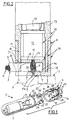
- Fig. 2 is a part sectional view of the device in question, taken along line II-II in Fig. 4;
- Fig. 3 shows the device in question in operating conditions, sectioned along line III-III in Fig. 4;
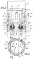
- Fig. 4 shows the device sectioned along the line IV-IV in Fig. 3.
- Referring to the drawings, a connecting device for electric components in accordance with the invention has been generally identified by reference numeral 1.
- In the embodiment shown the connecting device 1 is associated with a
bulb microlamp 2 known per se and conventional, for enabling connection of said lamp with a pair of conductors 3 each of which conventionally has acore 4 consisting of strands made of copper or other conductive material, surrounded by aninsulating sheath 5. - The device 1 comprises one connecting portion generally denoted by 6, exhibiting one or
more anchoring seats 7 each designed to house a terminal end 3a of one of the electric conductors 3. - In greater detail, in the case shown the presence of two of said
anchoring seats 7 is provided and they are disposed parallel in side by side relation preferably within a centralsmall base 8 of cylindrical conformation, rising from abase wall 9 of said first connectingportion 6. - Advantageously, the shape of each of the
anchoring seats 7 matches that of the terminal end 3a of the corresponding conductor 3 so that each seat completely encloses said terminal end and is in contact relationship with the outer surfaces thereof. In other words, the anchoringseats 7 have a diameter only marginally greater than the outer diameter of the insulating sheaths of the conductors 3, for the purposes to be clarified in the following. - Combined with the first connecting
portion 6 is a second connecting portion generally identified by 10, carrying one or moreelectric connecting elements 11 each arranged to electrically connect thecore 4 of one of the conductors 3 to themicrolamp 2 or other electric components with which the device 1 is associated. - In the embodiment shown, the second connecting
portion 10 comprises a supportingblock 12 in which said electric connectingelements 11 are engaged by a snug-fitting operation carried out in known manner. - This supporting block is rigidly housed, by snug-fitting for example, within a containing
capsule 13 preferably made of transparent plastic material, inside which themicrolamp 2 is located. The supportingblock 12 may also engage, in a manner known per se, one or moreelectric resistors 15 operatively interposed between the electric connectingelements 11 and thebulb microlamp 2. - In an original manner, in accordance with the present invention, each of the electric connecting
elements 11 is shaped as a piercing point substantially oriented in a fitting direction perpendicularly intersecting the longitudinal axis of therespective anchoring seat 7, to the ends better clarified in the following. - More particularly, each electric connecting
element 11 has a substantially plate-like structure, lying in a plane perpendicular to the longitudinal axis of therespective anchoring seat 7 having a wedge-shaped profile defined by two side edges 11b converging away from the supportingblock 12 as far as they meet at oneend 11a of the electric connecting element. - An engagement means 16 is associated with the first and second connecting
portions elements 11 operatively act in contact relationship on thecores 4 of the respective conductors 3. - Advantageously, said engagement means 16 essentially comprises a
coupling bush 17 and aguide collar 18 associated with the first and second connectingportions element 11. In more detail, theguide collar 18 is formed with one end of said containingcapsule 13 and thecoupling bush 17 projects perpendicularly from the perimetric edge of thebase wall 9 of the first connectingportion 6, encircling said centralsmall base 8. As clearly shown in Figs. 2 and 3, anannular groove 19 is defined between the centralsmall base 8 andcoupling bush 17, the end of theguide collar 18 being housed, in the operating condition, in said groove. - Advantageously, defined in the
coupling bush 17 andguide collar 18 are first andsecond side ports anchoring seats 7 and designed to be passed through by the conductors 3 emerging from the anchoring seats. Preferentially, thefirst side ports 20 also extend close to thebase wall 9 of the first connectingportion 6, so that the conductors 3 may be oriented at least in a direction substantially parallel to the fitting direction, as shown by chain line in Fig. 2. The presence of hooking elements 22 (also shown in chain line in Fig. 2) is also provided and they are associated with thebase wall 9 for holding the conductors 3 according to an orientation opposite to the respective terminal ends 3a introduced into theanchoring seats 7. - In accordance with the present invention, the engagement between the
guide collar 18 andcoupling bush 17 enables the mutual movement of the first and second connectingportions - In the preparatory arrangement condition, the
ends 11a of the electric connectingelements 11 are disengaged from therespective anchoring seats 7 so that the terminal ends 3a belonging to the corresponding conductors 3 can be fitted therein. In more detail, in the preparatory arrangement condition theends 11a of the electric connectingelements 11 are located inrespective access openings 23 defined in the centralsmall base 8 of the first connectingportion 6. - When the first and second connecting
portions elements 11 diametrically cross the terminal ends 3a of the corresponding conductors 3 piercing the insulating layer orsheath 5 and dividing the strands forming thecore 4 into two groups for engaging theirends 11a in correspondingretaining recesses 24 defined in thebase wall 9, within eachanchoring seat 7, on the side opposite to the respective access opening 23. - In the inserting condition, therefore, the conductive strands forming the
core 4 of each conductor 3 are in close contact with the diverging side edges 11b of the electric connectingelements 11 thereby ensuring an excellent electric continuity therewith. - Following the introduction of the electric connecting
elements 11 into and through the terminal ends 3a of the conductors 3, the terminal ends undergo a deformation involving a side expansion counteracted by the inner surfaces of thecorresponding anchoring seats 7 that, as previously described, are in a contact relationship on the insulatingsheaths 5 already in the preparatory arrangement condition. This situation further ensures the close contact and electric continuity between thecores 4 of the conductors 3 and theelectric connecting elements 11. - In order to fix the mutual positioning of the first and second connecting
portions first fitting lug 25 and at least onefirst coupling slot 26 are provided to be associated with the engagement means 16 and they are formed on theguide collar 18 andcoupling bush 17 respectively, so as to be mutually engaged by snap fitting, as clearly shown in Fig. 3. More particularly, in the embodiment shown the presence of a pair of saidfirst fitting lugs 25 andcoupling slots 26 is provided. - Each
first fitting lug 25 has an inclined slide side 25a at which forced sliding of thecoupling bush 17 moving towards the operating condition, occurs. The inclined side 25a is followed by an abutment shoulder 25b designed to act on an edge of thecoupling slot 26 when thefitting lug 25 snaps therein on reaching of the operating condition. - Preferably, also formed on the
guide collar 18 is at least onesecond fitting lug 27 suitably spaced apart from thefirst fitting lugs 25 with reference to the insertion direction. More particularly, the presence of a pair of saidsecond fitting lugs 27 is provided and each of them engages one of thefirst coupling slots 26 for fixing the mutual positioning of the first and second connectingportions first fitting lugs 25. This situation appears to be very advantageous for facilitating introduction of the terminal ends 3a of the conductors 3 into therespective anchoring seats 7, above all when the connecting operation is carried out by automated machines. - It is also advantageously provided that at least one
second coupling slot 28 be formed in thecoupling bush 17. In the embodiment shown there are twosecond coupling slots 28, suitably spaced apart from thefirst slots 26 with reference to the insertion direction, each of which being designed to operatively engage one of the second fitting lugs 27, as shown in Fig. 3, for helping the action of the first fitting lugs 25 in mutual fastening of the first and second connectingportions - The modalities of use of the present invention described above mainly as regards structure are very simple.
- The device 1 is preassembled to the preparatory arrangement condition by a mere operation consisting in fitting the
coupling bush 17 on theguide collar 18. - Under this situation, the connecting operation for enabling current supply to the
microlamp 2 only requires that the terminal ends 3a of the conductors 3 be introduced into the anchoringseats 7, stripping being unnecessary. Since the anchoringseats 7 are oriented parallel to each other, insertion of the conductors 3 can be easily carried out by a single operation. - Once the insertion is executed, the only operation to be done is pushing the first connecting
portion 6 to the operating condition for causing the simultaneous connection of the conductors 3 to themicrolamp 2, as a result of the conductors themselves being passed through by the electric connectingelements 11. - The present invention attains the intended purposes.
- It is in fact to be noted that in addition to greatly simplifying the connecting operations, the device in question is capable of ensuring an excellent connecting strength in terms of tractive efforts that may be imposed to the conductors 3.
- In the connection it is in fact to be noted that the electric connecting elements, while having very reduced sizes, are not subjected to bending under the effect of said tractive efforts, in that their
ends 11a are conveniently held in the respective retaining recesses 24. - In addition tractive stresses that would tend to make the conductor ends come out of the anchoring
seats 7 are conveniently counteracted by the adhesion created between the outer surfaces of the insulatingsheaths 5 and inner surfaces of the anchoring seats, following the forced expansion undergone by the terminal ends 3a when the electric connectingelements 11 are introduced thereinto. - It is also to be noted that due the conformation of the electric connecting
elements 11 in the form of a piercing point, tearing inevitably produced on the insulatingsheaths 5 is greatly reduced as compared to cases in which known devices are used. This aspect too considerably helps in improving the mechanical strength of the connection. - In addition, the use of electric connecting elements in the form of a piercing point enables the side dimensions of said electric connecting elements to be greatly reduced, which brings about an important reduction in the bulkiness of the whole device as compared to the devices of the known art, above all with reference to connections in which the conductors, connected side by side to each other through the respective insulating layers, form a single ribbon-like structure. Under this situation, the present invention enables arrangement in a single plane of as many electric connecting
elements 11 as the conductors to be connected, unlike the solutions of the known art where due to the greater bulkiness of the electric connecting elements, their distribution in offset rows is required. - Obviously many modifications and variations may be made to the invention as conceived, all falling within the scope of the appended claims.
Claims (13)
- A connecting device for electric components, comprising:said engagement means (16) comprising a guide collar (18) and a coupling bush (17) associated with the first and second connecting portions (6, 10) respectively, to be coaxially engaged by mutual sliding parallelly to said fitting direction, so that said conductors (3) are diametrically crossed by the respective electric connecting elements (11) in the operating condition.one connecting portion (6) carrying anchoring seats (7) arranged to house respective terminal ends (3a) of electric conductors (3), each exhibiting a core (4) made of conductive-material strands covered with an insulating sheath (5);a second connecting portion (10);electric connecting elements (11) each arranged to electrically connect the core (4) of one of said conductors (3) to one of said electric components (2) each of said electric connecting elements (11) being shaped as a piercing point substantially oriented in a fitting direction perpendicularly intersecting the longitudinal axis of the respective anchoring seat (7);engagement means (16) for mutually fastening the first and second connecting portions (6, 10) in an operating condition in which each of said electric connecting elements (11) acts in contact relationship on the core (4) of the respective conductor (3) across said insulating sheath (5) engaging one end (11a) thereof in a retaining recess (24), characterized in that, each of said electric connecting elements (11) is carried by the second connecting portion (10) and extends, in the operating condition, in the respective anchoring seat through an access opening (23) defined in the first connecting portion (6), said retaining recess (24) being defined within the anchoring seat (7) on the side opposite to the access opening (23),
- A device according to claim 1, characterized in that the shape of each of said anchoring seats (7) matches the shape of the terminal end (3a) of the respective conductor (3), each seat completely enclosing the conductor end and being in contact relationship with the outer surfaces thereof, so that the insulating sheath (5) arranged on the conductor is expanded by effect of the insertion of the electric connecting element (11) across the conductor (3) and acts in thrust relationship on the inner surfaces of the anchoring seats (7) in the operating condition.
- A device according to claim 1, characterized in that said engagement means (16) further comprises at least one first fitting lug (25) and at least one coupling slot (26), formed in the guide collar (18) and coupling bush (17) respectively, and capable of mutual engagement by snap fitting so as to fix the mutual positioning of the first and second connecting portions (6, 10) in the operating condition.
- A device according to claim 3, characterized in that it further comprises at least one second fitting lug (27) spaced apart from the first fitting lug (25) in the insertion direction and arranged to be engaged by snap fitting in said first coupling slot (26) for fixing the mutual positioning of the first and second connecting portions (6, 10) in a preparatory arrangement condition in which said electric connecting elements (11) are disengaged from the anchoring seats (7) for enabling introduction of the ends (3a) of the respective conductors (3) thereinto.
- A device according to claim 4, characterized in that it further comprises at least one second coupling slot (28) spaced apart from the first coupling shot (26) in the insertion direction and arranged to engage said second fitting lug (27) by snap fitting in the operating condition.
- A device according to claim 4, characterized in that in the preparatory arrangement condition the ends (11a) of the electric connecting elements (11) are located in register with said access openings (23).
- A device according to claim 1, characterized in that said second connecting portion (10) comprises a supporting block (12) from which said electric connecting elements (11) project and a containing capsule (13) exhibiting said guide collar (18) at one end thereof and internally engaging the supporting block (12), a bulb microlamp (2) housed in the containing capsule (13) being engaged to said supporting block (12) on the opposite side with respect to the electric connecting elements (11) and being electrically connected to the connecting elements themselves.
- A device according to claim 7, characterized in that said first connecting portion (6) comprises a base wall (9) and a central small base (8) projecting from the base wall (9) and encircled by said coupling bush (17), said anchoring seats (7) being formed within the central small base (6).
- A device according to claim 8, characterized in that said coupling bush (17) has first side ports (20) located in alignment with said anchoring seats (7) and arranged to be crossed by the conductors (3) emerging from the anchoring seats in the extension of the corresponding terminal ends (3a).
- A device according to claim 9, characterized in that said first side ports (20) stretch out at said base wall (9) in order to enable orientation of said conductors (3) at least in a direction substantially parallel to the insertion direction.
- A device according to claim 10, characterized in that it further comprises hooking elements (22) associated with said base wall (9), arranged to engage the conductors (3) emerging from the anchoring seats (7) and hold them according to an orientation opposite to the respective terminal ends (3a).
- A device according to claim 8, characterized in that an annular groove (19) is defined between said central small base (8) and coupling bush (17) for housing one end of the guide collar (18), in the operating condition.
- A device according to claim 11, characterized in that the end of the guide collar (18) exhibits second side ports (21) located in alignment with said anchoring seats (7) and arranged to be crossed by the conductors (3) emerging from the anchoring seats (7) in the extension of the respective terminal ends (3a).
Applications Claiming Priority (2)
| Application Number | Priority Date | Filing Date | Title |
|---|---|---|---|
| IT93MI001525A IT1265145B1 (en) | 1993-07-12 | 1993-07-12 | CONNECTION DEVICE FOR ELECTRIC COMPONENTS |
| ITMI931525 | 1993-07-12 |
Publications (3)
| Publication Number | Publication Date |
|---|---|
| EP0634820A2 EP0634820A2 (en) | 1995-01-18 |
| EP0634820A3 EP0634820A3 (en) | 1996-02-28 |
| EP0634820B1 true EP0634820B1 (en) | 1999-09-15 |
Family
ID=11366585
Family Applications (1)
| Application Number | Title | Priority Date | Filing Date |
|---|---|---|---|
| EP93830344A Expired - Lifetime EP0634820B1 (en) | 1993-07-12 | 1993-07-30 | Connecting device for electric components |
Country Status (6)
| Country | Link |
|---|---|
| US (1) | US5460539A (en) |
| EP (1) | EP0634820B1 (en) |
| AT (1) | ATE184735T1 (en) |
| DE (1) | DE69326458T2 (en) |
| ES (1) | ES2137979T3 (en) |
| IT (1) | IT1265145B1 (en) |
Families Citing this family (7)
| Publication number | Priority date | Publication date | Assignee | Title |
|---|---|---|---|---|
| DE59504938D1 (en) * | 1994-12-01 | 1999-03-04 | Andreas Hierzer | FUNCTIONAL LOW VOLTAGE POWER SUPPLY |
| JPH1167413A (en) * | 1997-08-20 | 1999-03-09 | Sumitomo Wiring Syst Ltd | Bulb socket, bulb socket-to-wire connection method, and bulb socket-to-wire connection jig |
| FR2771556B1 (en) * | 1997-11-26 | 2001-11-23 | Corinne Ferrero | CONNECTION DEVICE FOR SOCKET OF ELECTRIC BULBS |
| US6017241A (en) * | 1998-01-26 | 2000-01-25 | Tivoli Industries, Inc. | Aisle lighting lampholder |
| US6859031B2 (en) | 2002-02-01 | 2005-02-22 | Credence Systems Corporation | Apparatus and method for dynamic diagnostic testing of integrated circuits |
| DE102009018714B3 (en) * | 2009-04-27 | 2010-12-02 | Phoenix Contact Gmbh & Co. Kg | Cable connecting device |
| TWM468614U (en) * | 2013-04-23 | 2013-12-21 | Chang-Fu Tsai | Flexible head structure of LED light string |
Family Cites Families (11)
| Publication number | Priority date | Publication date | Assignee | Title |
|---|---|---|---|---|
| US3859554A (en) * | 1968-05-13 | 1975-01-07 | Westinghouse Electric Corp | Electric lamp with integral plastic base member |
| DE2617450C3 (en) * | 1976-04-21 | 1979-02-22 | Hentges & Schmidt, 5880 Luedenscheid | Socket for a candle light |
| GB2088148B (en) * | 1980-10-24 | 1985-01-23 | Bicc Burndy Ltd | Electric connector |
| US4631650A (en) * | 1984-10-24 | 1986-12-23 | Ahroni Joseph M | Series-parallel connected miniature light set |
| US5121310A (en) * | 1984-10-24 | 1992-06-09 | Ahroni Joseph M | Chaser decorative light set |
| CH666952A5 (en) * | 1986-04-24 | 1988-08-31 | Universo Sa | MINIATURE LAMP HOLDER. |
| US4768139A (en) * | 1987-04-27 | 1988-08-30 | Gty Industries | Lighting fixture |
| US5154508A (en) * | 1990-01-05 | 1992-10-13 | Ahroni Joseph M | Locking system for light assembly with push-in bulb unit |
| US5172026A (en) * | 1990-05-21 | 1992-12-15 | Hall Rolland B | Plug in lamp |
| FR2682226B1 (en) * | 1991-10-08 | 1993-11-12 | Barelec | LAMP SUPPORT. |
| US5252888A (en) * | 1991-12-30 | 1993-10-12 | Gte Products Corporation | Lamp capsule support base |
-
1993
- 1993-07-12 IT IT93MI001525A patent/IT1265145B1/en active IP Right Grant
- 1993-07-30 AT AT93830344T patent/ATE184735T1/en not_active IP Right Cessation
- 1993-07-30 DE DE69326458T patent/DE69326458T2/en not_active Expired - Fee Related
- 1993-07-30 EP EP93830344A patent/EP0634820B1/en not_active Expired - Lifetime
- 1993-07-30 ES ES93830344T patent/ES2137979T3/en not_active Expired - Lifetime
-
1994
- 1994-07-07 US US08/271,435 patent/US5460539A/en not_active Expired - Fee Related
Also Published As
| Publication number | Publication date |
|---|---|
| ITMI931525A0 (en) | 1993-07-12 |
| DE69326458D1 (en) | 1999-10-21 |
| ES2137979T3 (en) | 2000-01-01 |
| ITMI931525A1 (en) | 1995-01-12 |
| ATE184735T1 (en) | 1999-10-15 |
| US5460539A (en) | 1995-10-24 |
| EP0634820A3 (en) | 1996-02-28 |
| DE69326458T2 (en) | 1999-12-30 |
| IT1265145B1 (en) | 1996-10-31 |
| EP0634820A2 (en) | 1995-01-18 |
Similar Documents
| Publication | Publication Date | Title |
|---|---|---|
| US4051383A (en) | Electrical harnesses and connecting devices therefor | |
| US3723948A (en) | Electrical component | |
| US4533199A (en) | IDC termination for coaxial cable | |
| US3702456A (en) | Electrical terminal block for interconnecting a plurality of conductors | |
| US3916516A (en) | Electrical connector and method for making an electrical circuit | |
| GB1588841A (en) | Electrical terminal assemblies | |
| US4614028A (en) | Electrical assembly and method for arranging a plurality of electrical conductors in a pattern | |
| US5035655A (en) | Light bulb receptacle and method of assembly | |
| EP0615306B1 (en) | Commoning electrical connectors | |
| JPH0834111B2 (en) | Wire holding device | |
| US5871369A (en) | Connector | |
| EP0634820B1 (en) | Connecting device for electric components | |
| US5061203A (en) | Magnetic ballast connector system | |
| JP2516089B2 (en) | Connector wiring structure and method | |
| US4239320A (en) | Electrical connector | |
| US20020031937A1 (en) | Cable connector | |
| US4831726A (en) | Wiring harness and method for manufacturing same | |
| US6007367A (en) | Apparatus for connecting cable cores | |
| US20020037666A1 (en) | Connector terminals for a junction connector used in wire harnesses | |
| JPH06168747A (en) | Plug-in contact element for cable plug connector | |
| US4725247A (en) | Cable splicing assembly | |
| US4662067A (en) | Apparatus and method for providing orientation of a coax cable having a ground termination bar | |
| US5660563A (en) | Assembly of multi-terminal telecommunications connectors and terminals | |
| US4266843A (en) | Insulation displacing electrical contact and method of making same | |
| JPS60240072A (en) | Electric connector and method of producing same |
Legal Events
| Date | Code | Title | Description |
|---|---|---|---|
| PUAI | Public reference made under article 153(3) epc to a published international application that has entered the european phase |
Free format text: ORIGINAL CODE: 0009012 |
|
| AK | Designated contracting states |
Kind code of ref document: A2 Designated state(s): AT BE CH DE DK ES FR GB IE LI NL PT |
|
| PUAL | Search report despatched |
Free format text: ORIGINAL CODE: 0009013 |
|
| AK | Designated contracting states |
Kind code of ref document: A3 Designated state(s): AT BE CH DE DK ES FR GB IE LI NL PT |
|
| 17P | Request for examination filed |
Effective date: 19960822 |
|
| RAP1 | Party data changed (applicant data changed or rights of an application transferred) |
Owner name: GALLONE, LEONARDO Owner name: GALLONE, LYDIA CLAIRE Owner name: GALLONE, ELISA ELETTRA Owner name: GALLONE, FIAMMETTA Owner name: GALLONE, LAURA Owner name: GALLONE, MARCO Owner name: GALLONE, FLAVIO |
|
| RIN1 | Information on inventor provided before grant (corrected) |
Inventor name: GALLONE, CESARE |
|
| RAP1 | Party data changed (applicant data changed or rights of an application transferred) |
Owner name: GALLONE, LEONARDO Owner name: GALLONE, LYDIA CLAIRE Owner name: GALLONE, ELISA ELETTRA Owner name: GALLONE, FIAMMETTA Owner name: GALLONE, LAURA Owner name: GALLONE, FLAVIO |
|
| RAP1 | Party data changed (applicant data changed or rights of an application transferred) |
Owner name: SIGNAL LUX INTERNATIONAL S.A. |
|
| RAP1 | Party data changed (applicant data changed or rights of an application transferred) |
Owner name: SIGNAL LUX INTERNATIONAL S.A. |
|
| 17Q | First examination report despatched |
Effective date: 19980928 |
|
| GRAG | Despatch of communication of intention to grant |
Free format text: ORIGINAL CODE: EPIDOS AGRA |
|
| GRAG | Despatch of communication of intention to grant |
Free format text: ORIGINAL CODE: EPIDOS AGRA |
|
| GRAH | Despatch of communication of intention to grant a patent |
Free format text: ORIGINAL CODE: EPIDOS IGRA |
|
| GRAH | Despatch of communication of intention to grant a patent |
Free format text: ORIGINAL CODE: EPIDOS IGRA |
|
| GRAA | (expected) grant |
Free format text: ORIGINAL CODE: 0009210 |
|
| AK | Designated contracting states |
Kind code of ref document: B1 Designated state(s): AT BE CH DE DK ES FR GB IE LI NL PT |
|
| PG25 | Lapsed in a contracting state [announced via postgrant information from national office to epo] |
Ref country code: AT Free format text: LAPSE BECAUSE OF FAILURE TO SUBMIT A TRANSLATION OF THE DESCRIPTION OR TO PAY THE FEE WITHIN THE PRESCRIBED TIME-LIMIT Effective date: 19990915 |
|
| REF | Corresponds to: |
Ref document number: 184735 Country of ref document: AT Date of ref document: 19991015 Kind code of ref document: T |
|
| REG | Reference to a national code |
Ref country code: CH Ref legal event code: NV Representative=s name: ISLER & PEDRAZZINI AG Ref country code: CH Ref legal event code: EP |
|
| ET | Fr: translation filed | ||
| REF | Corresponds to: |
Ref document number: 69326458 Country of ref document: DE Date of ref document: 19991021 |
|
| REG | Reference to a national code |
Ref country code: IE Ref legal event code: FG4D |
|
| PG25 | Lapsed in a contracting state [announced via postgrant information from national office to epo] |
Ref country code: PT Free format text: LAPSE BECAUSE OF FAILURE TO SUBMIT A TRANSLATION OF THE DESCRIPTION OR TO PAY THE FEE WITHIN THE PRESCRIBED TIME-LIMIT Effective date: 19991215 Ref country code: DK Free format text: LAPSE BECAUSE OF FAILURE TO SUBMIT A TRANSLATION OF THE DESCRIPTION OR TO PAY THE FEE WITHIN THE PRESCRIBED TIME-LIMIT Effective date: 19991215 |
|
| REG | Reference to a national code |
Ref country code: ES Ref legal event code: FG2A Ref document number: 2137979 Country of ref document: ES Kind code of ref document: T3 |
|
| PLBE | No opposition filed within time limit |
Free format text: ORIGINAL CODE: 0009261 |
|
| STAA | Information on the status of an ep patent application or granted ep patent |
Free format text: STATUS: NO OPPOSITION FILED WITHIN TIME LIMIT |
|
| 26N | No opposition filed | ||
| PGFP | Annual fee paid to national office [announced via postgrant information from national office to epo] |
Ref country code: DE Payment date: 20010723 Year of fee payment: 9 |
|
| PGFP | Annual fee paid to national office [announced via postgrant information from national office to epo] |
Ref country code: GB Payment date: 20010725 Year of fee payment: 9 |
|
| PGFP | Annual fee paid to national office [announced via postgrant information from national office to epo] |
Ref country code: IE Payment date: 20010727 Year of fee payment: 9 |
|
| PGFP | Annual fee paid to national office [announced via postgrant information from national office to epo] |
Ref country code: NL Payment date: 20010730 Year of fee payment: 9 Ref country code: CH Payment date: 20010730 Year of fee payment: 9 |
|
| PGFP | Annual fee paid to national office [announced via postgrant information from national office to epo] |
Ref country code: FR Payment date: 20010731 Year of fee payment: 9 |
|
| PGFP | Annual fee paid to national office [announced via postgrant information from national office to epo] |
Ref country code: ES Payment date: 20010824 Year of fee payment: 9 |
|
| PGFP | Annual fee paid to national office [announced via postgrant information from national office to epo] |
Ref country code: BE Payment date: 20010918 Year of fee payment: 9 |
|
| REG | Reference to a national code |
Ref country code: GB Ref legal event code: IF02 |
|
| PG25 | Lapsed in a contracting state [announced via postgrant information from national office to epo] |
Ref country code: IE Free format text: LAPSE BECAUSE OF NON-PAYMENT OF DUE FEES Effective date: 20020730 Ref country code: GB Free format text: LAPSE BECAUSE OF NON-PAYMENT OF DUE FEES Effective date: 20020730 |
|
| PG25 | Lapsed in a contracting state [announced via postgrant information from national office to epo] |
Ref country code: LI Free format text: LAPSE BECAUSE OF NON-PAYMENT OF DUE FEES Effective date: 20020731 Ref country code: ES Free format text: LAPSE BECAUSE OF NON-PAYMENT OF DUE FEES Effective date: 20020731 Ref country code: CH Free format text: LAPSE BECAUSE OF NON-PAYMENT OF DUE FEES Effective date: 20020731 Ref country code: BE Free format text: LAPSE BECAUSE OF NON-PAYMENT OF DUE FEES Effective date: 20020731 |
|
| BERE | Be: lapsed |
Owner name: S.A. *SIGNAL LUX INTERNATIONAL Effective date: 20020731 |
|
| PG25 | Lapsed in a contracting state [announced via postgrant information from national office to epo] |
Ref country code: NL Free format text: LAPSE BECAUSE OF NON-PAYMENT OF DUE FEES Effective date: 20030201 Ref country code: DE Free format text: LAPSE BECAUSE OF NON-PAYMENT OF DUE FEES Effective date: 20030201 |
|
| REG | Reference to a national code |
Ref country code: CH Ref legal event code: PL |
|
| GBPC | Gb: european patent ceased through non-payment of renewal fee |
Effective date: 20020730 |
|
| PG25 | Lapsed in a contracting state [announced via postgrant information from national office to epo] |
Ref country code: FR Free format text: LAPSE BECAUSE OF NON-PAYMENT OF DUE FEES Effective date: 20030331 |
|
| NLV4 | Nl: lapsed or anulled due to non-payment of the annual fee |
Effective date: 20030201 |
|
| REG | Reference to a national code |
Ref country code: FR Ref legal event code: ST |
|
| REG | Reference to a national code |
Ref country code: IE Ref legal event code: MM4A |
|
| REG | Reference to a national code |
Ref country code: ES Ref legal event code: FD2A Effective date: 20030811 |