EP0634811A1 - Shear bolt screw - Google Patents
Shear bolt screw Download PDFInfo
- Publication number
- EP0634811A1 EP0634811A1 EP94109586A EP94109586A EP0634811A1 EP 0634811 A1 EP0634811 A1 EP 0634811A1 EP 94109586 A EP94109586 A EP 94109586A EP 94109586 A EP94109586 A EP 94109586A EP 0634811 A1 EP0634811 A1 EP 0634811A1
- Authority
- EP
- European Patent Office
- Prior art keywords
- tear
- shear
- head
- threaded body
- shear bolt
- Prior art date
- Legal status (The legal status is an assumption and is not a legal conclusion. Google has not performed a legal analysis and makes no representation as to the accuracy of the status listed.)
- Withdrawn
Links
- 230000007704 transition Effects 0.000 claims description 41
- 238000010008 shearing Methods 0.000 claims description 11
- 239000011324 bead Substances 0.000 claims description 5
- 230000006378 damage Effects 0.000 description 5
- 208000027418 Wounds and injury Diseases 0.000 description 3
- 208000014674 injury Diseases 0.000 description 3
- 238000004519 manufacturing process Methods 0.000 description 3
- 239000000463 material Substances 0.000 description 3
- 229910001369 Brass Inorganic materials 0.000 description 1
- 208000000260 Warts Diseases 0.000 description 1
- 239000000956 alloy Substances 0.000 description 1
- 229910045601 alloy Inorganic materials 0.000 description 1
- 239000010951 brass Substances 0.000 description 1
- 230000015556 catabolic process Effects 0.000 description 1
- 239000004020 conductor Substances 0.000 description 1
- 238000005516 engineering process Methods 0.000 description 1
- 238000003754 machining Methods 0.000 description 1
- 239000002184 metal Substances 0.000 description 1
- 238000000034 method Methods 0.000 description 1
- 201000010153 skin papilloma Diseases 0.000 description 1
Images

Classifications
-
- F—MECHANICAL ENGINEERING; LIGHTING; HEATING; WEAPONS; BLASTING
- F16—ENGINEERING ELEMENTS AND UNITS; GENERAL MEASURES FOR PRODUCING AND MAINTAINING EFFECTIVE FUNCTIONING OF MACHINES OR INSTALLATIONS; THERMAL INSULATION IN GENERAL
- F16B—DEVICES FOR FASTENING OR SECURING CONSTRUCTIONAL ELEMENTS OR MACHINE PARTS TOGETHER, e.g. NAILS, BOLTS, CIRCLIPS, CLAMPS, CLIPS OR WEDGES; JOINTS OR JOINTING
- F16B31/00—Screwed connections specially modified in view of tensile load; Break-bolts
- F16B31/02—Screwed connections specially modified in view of tensile load; Break-bolts for indicating the attainment of a particular tensile load or limiting tensile load
- F16B31/021—Screwed connections specially modified in view of tensile load; Break-bolts for indicating the attainment of a particular tensile load or limiting tensile load by means of a frangible part
-
- H—ELECTRICITY
- H01—ELECTRIC ELEMENTS
- H01R—ELECTRICALLY-CONDUCTIVE CONNECTIONS; STRUCTURAL ASSOCIATIONS OF A PLURALITY OF MUTUALLY-INSULATED ELECTRICAL CONNECTING ELEMENTS; COUPLING DEVICES; CURRENT COLLECTORS
- H01R4/00—Electrically-conductive connections between two or more conductive members in direct contact, i.e. touching one another; Means for effecting or maintaining such contact; Electrically-conductive connections having two or more spaced connecting locations for conductors and using contact members penetrating insulation
- H01R4/28—Clamped connections, spring connections
- H01R4/30—Clamped connections, spring connections utilising a screw or nut clamping member
Definitions
- the invention relates to a shear-off screw, with a threaded body with an external thread, and with a tear-off head with a contact surface for a tool, a transition region being located between the threaded body and the tear-off head, which has a smaller outer diameter than the threaded body.
- Shear bolts of this type are known in various designs and are used, for example, to reliably fasten cables in screw connectors or cable connection terminals. Such shear bolts have a transition area which has a predetermined breaking point at which the tear-off head tears off when a predetermined torque is reached or exceeded when the shear bolt is tightened.
- Tearing off the tear-off head shows that a sufficiently large contact pressure has been applied, which has been set by the predetermined breaking point so that no damage to the conductors or wires of a cable can occur.
- shrink sleeves are often shrunk onto electrical fittings with such mounted screws, so that such rough and / or sharp-edged fractured surfaces with their naturally unprocessed surface structure can injure such shrink sleeves, with the result that they tear easily.
- a further disadvantage can occur if slide-on parts or insulating parts are mounted over such arrangements, for example in the case of cable connecting sleeves. Then, due to the rough predetermined breaking point, injuries can occur on the surface of the plastic insulating parts, with the result that the dielectric strength of the fitting is reduced. Glow discharges and voltage breakdowns can be caused by such scratches.
- the invention is therefore based on the object of specifying a shear bolt of the type mentioned at the outset which improves and ensures safer handling when used.
- the problem is solved in a satisfactory manner with the shear screw according to the invention. Characterized in that the predetermined breaking point and thus the resulting fracture surface is lower than the upper end of the threaded body in the axial direction of the screw, injuries to fitters and fittings to be assembled can be avoided in a reliable manner.
- transition region ends in a circumferential shearing groove which then defines the fracture surface.
- the transition region itself can extend cylindrically from the tear-off head to the threaded body, but it is preferably formed increasingly tapering up to the shearing groove.
- the transition region is formed by a truncated cone-shaped body, the outer contour of which in cross section is a straight line or an arc-shaped curve with respect to the axis of the shear screw.
- Such contours can be easily manufactured in terms of production technology and enable an exact setting of the predetermined breaking point or the torque at which the tear-off head of the shear screw shears off reliably.
- the transition area merges at its lower end into an inclined surface in the threaded body and that the inclined surface has a greater inclination than the transition region relative to the axis of the shear screw and forms the shear groove together with the transition region.
- Such inclined surfaces can be easily worked into a rod material from which the shear bolts are formed.
- the upper end of the threaded body is in the form of an annular bead which surrounds the shearing groove in the circumferential direction and whose surface facing the tear-off head is finished.
- the bead thus forms an external protection against the shear-off groove and, viewed in the axial direction of the screw, projects outward beyond its fracture surface.
- the surface is smooth, namely finished or possibly also polished, so that this smooth surface makes it easier to slide on insulating parts or shrink sleeves without damaging them.
- the shearing groove is formed by two surfaces which intersect at an angle of approximately 10 ° to 60 °. In this way, the shear screw can be easily manufactured as a turned part.
- the upper end of the threaded body has a further inclined surface which slopes outwards towards the external thread.
- the tear-off head has an inner recess in the form of an inner edge, preferably an inner hexagon, which extends at least into the transition region.
- Such screws can be operated with conventional tools.
- the wall thickness between the transition area and the inner edge can be used to set the torque at which the tear-off head is sheared off.
- the inner edge extends with a constant cross-section over its depth from the tear-off head into the threaded body and that the transition area above the shear-off groove has at least one protrusion projecting transversely into the interior of the inner edge.
- Such an internal recess can be produced in one operation, which simplifies production.
- the projection forms a support for a tool to be used and at the same time a lock that reliably prevents the tool from being used too far.
- the tear-off head tears off at the predetermined breaking point of the transition region at a specific predetermined tightening torque.
- the tear-off head tears off at the predetermined breaking point of the transition region at a specific predetermined tightening torque.
- the projection protruding into the inner recess is removed at the same time. Then the inner edge in the area of the threaded body is immediately freely accessible. By re-attaching a tool, the screwed-in threaded body can be loosened if necessary.
- the respective projection is formed in the extension of a radially extending recess in the transition area.
- the projection is a projection which projects radially inwards, is stamped in or pressed in from the outside. This can be easily produced with a punch or a punch. If a radially extending depression is provided in the transition area, this can advantageously serve as a guide for the respective tool in order to produce the respective projection.
- the projection is designed as a pin which extends across the wall of the transition region and extends at least partially radially into the interior of the inner edge.
- the pin can extend through a corresponding radially extending recess in the transition region and can completely or partially penetrate the interior of the inner edge in the radial direction.
- the threaded body has a spherically shaped round tip at its front end.
- Such screws ensure particularly good mechanical and electrical contact with a part to be connected, without this being damaged when the shear screw is tightened.
- the front end it is also possible to design the front end with another suitable shape, for example cylindrical, frustoconical or tapering, if this is expedient for the respective application.
- the transition region and the threaded body of the shear screw are designed to be rotationally symmetrical.
- the tear-off head can of course also be designed to be rotationally symmetrical. In this way it is possible to produce the screw according to the invention from a bar material and to bring the cut pieces into the desired configuration by machining.
- the tear-off head of the screw according to the invention can (additionally) have an outer edge on its outer circumference, preferably an outer hexagon, if the use of a corresponding, externally acting tool is to be made possible.
- the tear-off head has at least one circumferential groove on its outer circumference.
- Such grooves can facilitate the handling of the screw and can also serve as markings to signal certain mechanical properties, for example certain tightening torques at which the tear-off head shears off.
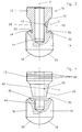
- a shear screw 10 which is formed from a cylindrical blank, which can for example consist of brass or another metal or another alloy. Symmetrical to the central axis X of a shear head 12, a transition region 20, a Abscherrille 22, a threaded body 14 and a rounded end 18 with a spherical contact surface 26 are provided at the front end of the shear bolt 10 from top to bottom, these parts being suitably rotationally symmetrical about the central axis X are trained.
- the tear-off head 12 merges into the transition region 20, which is designed as a truncated cone, the outer contour 28 of which in cross section is a straight line or arcuate curve with respect to the central axis X of the shear screw 10, which can be parabolic or hyperbolic, for example.
- the transition area need not be graduated, as shown in FIG. 1, but can be delimited by a continuous, oblique line.
- the transition region 20 tapers increasingly from the tear-off head 12 to the threaded body 14 and ends in a shear-off groove 22 which lies deeper than the upper end 30 of the threaded body 14 facing the tear-off head 12.
- the shear-off screw 10 an inclined surface 32, which has a greater inclination with respect to the central axis X of the shear screw 10 than the transition region 20 itself.
- the outer contour 28 of the transition region 20 and the inclined surface 32 then together form the shear groove 22, the diameter of which is selected in accordance with the desired maximum tightening torque, in which the tear-off head 12 is to shear off.
- the inclined surface 32 thus delimits an annular bead on the radially inner side, which surrounds the shearing groove 22 in the circumferential direction and whose surface facing the tear-off head 12 is smoothed, in particular is sized. If desired, this surface can also be machined, for example polished.
- This bead or its upper end 30 on the threaded body 14 expediently has a further inclined surface 34 which slopes outwards towards an external thread 16.
- the height of the external thread 16 can then be set so that it completely disappears when the shear screw is installed in a corresponding internal thread, so that after tightening the shear screw 10 and shearing off the tear-off head 12 only the smooth surface of the upper end 30 is accessible from the outside and pushing on shrink sleeves or other insulating parts facilitated.
- a schematically indicated inner edge 24 for example an internal hexagon, which is used to hold a tool to actuate the shear screw.
- an outer edge (not shown), in particular an outer hexagon, can be provided on the tear-off head 12 if the use of a corresponding, externally acting tool is to be made possible.
- the angle between the outer contour 28 and the inclined surface 32 is approximately 30 °, but this angle can generally be in the order of magnitude between 10 ° and 60 ° to the position of the shear groove in relation to the upper one End 30 of the threaded body 14 to be set precisely so that the fracture surface 36 is reliably below the upper end 30 after the tear-off head 12 has been sheared off. Then it is guaranteed that this fractured surface with its unworked surface structure cannot cause any danger during further use and processing.
- This distance between the fracture surface 36 and the upper end 30 will expediently be of the order of a few millimeters.
- the second embodiment according to FIGS. 3 and 4 has a similar structure in principle.
- the inner edge 44 is formed with a constant cross-section over its depth from the tear-off head 12 into the threaded body 14, the transition region 20 above the shear groove 22 has at least one projection 42 projecting transversely into the interior of the inner edge 44.
- the respective projection 42 can be formed in the extension of a radially extending recess 40 along a transverse axis Y in the transition region 20.
- the projection can be a projection 42 which projects radially inwards, is stamped in or pressed in from the outside.
- the depression 40 tapering in the direction of the transverse axis Y can serve as a guide for a tool in order to press or impress this projection.
- such a projection can also be designed as a pin which extends across the wall of the transition region 20 and which extends at least partially radially in the direction of the transverse axis Y into the interior of the inner edge 44.
- FIGS. 3 and 4 While only one such projection 42 is indicated in FIGS. 3 and 4, two or more such projections 42 can of course also be provided, which can expediently be located approximately at the same height in the circumferential direction around the central axis X.
- the uniformly formed inner edge 44 is divided into two areas, namely at a predetermined location above the shear groove 22. This ensures that an actuating tool for the The shear screw 10 has a sufficiently large contact surface both for screwing in the shear screw 10 and for any loosening of the screwed-in threaded body 14, the tool being able to be used sufficiently far in both assembly processes.
- Such projections 42 can be attached in a simple manner, but they nevertheless reliably prevent a tool for mounting the shear screw 10 from being used too far. Incorrect operation can thus be reliably excluded. If the shear bolt 10 has been installed and the force for screwing in has exceeded the predetermined limit value, the tear-off head 12 shears off together with the transition region 20 on the shear-off groove 22, the respective projections 42 remaining in this separated part. The area of the inner edge 44 below the shear groove 22 can then be used to loosen the screwed-in part of the shear screw 10, that is, the clamped threaded body 14.
- the shape of the transition region 20 and the positioning of the shear groove 22 ensure that the fracture surface 36 lies clearly below the upper end 30 of the threaded body 14 and thus cannot cause any undesirable damage.
- these grooves 38 can be used to classify the respective shear bolts 10 with regard to their technical properties, in particular with regard to the maximum tightening torque at which the transition region shears off at the shear groove 22 as a predetermined breaking point.
Landscapes
- Engineering & Computer Science (AREA)
- General Engineering & Computer Science (AREA)
- Mechanical Engineering (AREA)
- Hand Tools For Fitting Together And Separating, Or Other Hand Tools (AREA)
Abstract
Description
Die Erfindung betrifft eine Abscherschraube, mit einem Gewindekörper mit einem Außengewinde, und mit einem Abreißkopf mit Angriffsfläche für ein Werkzeug, wobei sich zwischen dem Gewindekörper und dem Abreißkopf ein Übergangsbereich befindet, der einen kleineren Außendurchmesser als der Gewindekörper hat.The invention relates to a shear-off screw, with a threaded body with an external thread, and with a tear-off head with a contact surface for a tool, a transition region being located between the threaded body and the tear-off head, which has a smaller outer diameter than the threaded body.
Derartige Abscherschrauben sind in verschiedenen Bauformen bekannt und werden beispielsweise dazu verwendet, Kabel in Schraubverbindern oder Kabelverbindungsklemmen in zuverlässiger Weise zu befestigen. Solche Abscherschrauben haben einen Übergangsbereich, der eine Sollbruchstelle, an der der Abreißkopf dann abreißt, wenn beim Anziehen der Abscherschraube ein vorgegebenes Drehmoment erreicht bzw. überschritten wird, aufweist.Shear bolts of this type are known in various designs and are used, for example, to reliably fasten cables in screw connectors or cable connection terminals. Such shear bolts have a transition area which has a predetermined breaking point at which the tear-off head tears off when a predetermined torque is reached or exceeded when the shear bolt is tightened.
Auf diese Weise ist sichergestellt, daß die Adern eines Kabels in einer Kabelklemme einerseits mit ausreichender Kraft angepreßt und festgehalten werden, andererseits solche Adern des Kabels nicht beschädigt oder durchgequetscht werden können, wenn zu große Anzugsdrehmomente verwendet werden. Das Abreißen des Abreißkopfes zeigt nämlich, daß eine ausreichend große Anpreßkraft aufgewendet worden ist, die durch die Sollbruchstelle so eingestellt worden ist, daß keine Beschädigung der Leiter oder Adern eines Kabels eintreten können.This ensures that the wires of a cable in a cable clamp are sufficiently strong pressed and held, on the other hand, such wires of the cable can not be damaged or squeezed if excessive tightening torques are used. Tearing off the tear-off head shows that a sufficiently large contact pressure has been applied, which has been set by the predetermined breaking point so that no damage to the conductors or wires of a cable can occur.
Bei solchen Abscherschrauben kann aber in der Praxis das Problem auftreten, daß nach dem Abscheren des Abreißkopfes an der abgescherten Sollbruchstelle eine rauhe Oberfläche an der Oberseite des Gewindekörpers stehenbleibt, die scharfkantige Grate hat. Da diese Bruchfläche am Gewindekörper zugleich das äußere bzw. obere Ende des Gewindekörpers und damit des wirksamen Teiles der eigentlichen Schraube bildet, ergeben sich aus dieser Konstellation Nachteile bei der weiteren Handhabung.With such shear-off screws, however, the problem can arise in practice that after the shear-off head is sheared off, a rough surface remains on the upper side of the threaded body at the sheared predetermined breaking point and has sharp-edged burrs. Since this fracture surface on the threaded body also forms the outer or upper end of the threaded body and thus the effective part of the actual screw, this constellation results in disadvantages in further handling.
Einerseits besteht Verletzungsgefahr für einen Benutzer oder Monteur, andererseits werden häufig Schrumpfschläuche auf Elektroarmaturen mit derartigen montierten Schrauben aufgeschrumpft, so daß solche rauhen und/oder scharfkantigen Bruchflächen mit ihrer naturgemäß unbearbeiteten Oberflächenstruktur solche Schrumpfschläuche verletzen können, mit der Folge, daß diese leicht einreißen. Ein weiterer Nachteil kann dann auftreten, wenn Aufschiebeteile bzw. Isolierteile über solchen Anordnungen montiert werden, beispielsweise bei Kabel-Verbindungsmuffen. Dann können nämlich durch die rauhe Sollbruchstelle Verletzungen an der Oberfläche der Kunststoff-Isolierteile auftreten, mit der Folge, daß die Spannungsfestigkeit der Armatur verringert wird. An solchen Kratzern können beispielsweise Glimmentladungen und Spannungsdurchschläge verursacht werden.On the one hand, there is a risk of injury to a user or fitter, on the other hand, shrink sleeves are often shrunk onto electrical fittings with such mounted screws, so that such rough and / or sharp-edged fractured surfaces with their naturally unprocessed surface structure can injure such shrink sleeves, with the result that they tear easily. A further disadvantage can occur if slide-on parts or insulating parts are mounted over such arrangements, for example in the case of cable connecting sleeves. Then, due to the rough predetermined breaking point, injuries can occur on the surface of the plastic insulating parts, with the result that the dielectric strength of the fitting is reduced. Glow discharges and voltage breakdowns can be caused by such scratches.
Der Erfindung liegt daher die Aufgabe zugrunde, eine Abscherschraube der eingangs genannten Art anzugeben, die eine verbesserte und sicherere Handhabung bei ihrer Verwendung gewährleistet.The invention is therefore based on the object of specifying a shear bolt of the type mentioned at the outset which improves and ensures safer handling when used.
Mit der erfindungsgemäßen Abscherschraube wird das Problem in zufriedenstellender Weise gelöst. Dadurch, daß in Achsenrichtung der Schraube die Sollbruchstelle und damit die entstehende Bruchfläche tiefer liegt als das obere Ende des Gewindekörpers, können Verletzungen von Monteuren und zu montierenden Armaturen in zuverlässiger Weise vermieden werden.The problem is solved in a satisfactory manner with the shear screw according to the invention. Characterized in that the predetermined breaking point and thus the resulting fracture surface is lower than the upper end of the threaded body in the axial direction of the screw, injuries to fitters and fittings to be assembled can be avoided in a reliable manner.
Dies wird vorzugsweise dadurch erreicht, daß der Übergangsbereich in einer in Umfangsrichtung verlaufenden Abscherrille endet, die dann die Bruchfläche definiert. Der Übergangsbereich selbst kann sich vom Abreißkopf zum Gewindekörper hin zylindrisch erstrecken, vorzugsweise ist er aber sich zunehmend verjüngend bis zur Abscherrille ausgebildet.This is preferably achieved in that the transition region ends in a circumferential shearing groove which then defines the fracture surface. The transition region itself can extend cylindrically from the tear-off head to the threaded body, but it is preferably formed increasingly tapering up to the shearing groove.
In Weiterbildung der erfindungsgemäßen Schraube ist vorgesehen, daß der Übergangsbereich von einem kegelstumpfartigen Körper gebildet ist, dessen Außenkontur im Querschnitt eine gegenüber der Achse der Abscherschraube schräg verlaufende Gerade oder bogenförmig verlaufende Kurve ist. Derartige Konturen lassen sich fertigungstechnisch einfach herstellen und ermöglichen eine exakte Einstellung der Sollbruchstelle bzw. des Drehmomentes, bei dem der Abreißkopf der Abscherschraube zuverlässig abschert.In a further development of the screw according to the invention, it is provided that the transition region is formed by a truncated cone-shaped body, the outer contour of which in cross section is a straight line or an arc-shaped curve with respect to the axis of the shear screw. Such contours can be easily manufactured in terms of production technology and enable an exact setting of the predetermined breaking point or the torque at which the tear-off head of the shear screw shears off reliably.
In Weiterbildung der erfindungsgemäßen Schraube ist vorgesehen, daß der Übergangsbereich an seinem unteren Ende in eine Schrägfläche im Gewindekörper übergeht und daß die Schrägfläche gegenüber der Achse der Abscherschraube eine größere Neigung als der Übergangsbereich hat und zusammen mit dem Übergangsbereich die Abscherrille bildet. Derartige Schrägflächen lassen sich in einfacher Weise in ein Stangenmaterial einarbeiten, aus dem die Abscherschrauben geformt werden.In a further development of the screw according to the invention it is provided that the transition area merges at its lower end into an inclined surface in the threaded body and that the inclined surface has a greater inclination than the transition region relative to the axis of the shear screw and forms the shear groove together with the transition region. Such inclined surfaces can be easily worked into a rod material from which the shear bolts are formed.
Besonders zweckmäßig ist es, wenn bei der erfindungsgemäßen Schraube das obere Ende des Gewindekörpers als ringförmiger Wulst ausgebildet ist, der die Abscherrille in Umfangsrichtung umgibt und dessen dem Abreißkopf zugewandte Oberfläche geschlichtet ist. Der Wulst bildet somit einen äußeren Schutz gegenüber der Abscherrille und steht, in axialer Richtung der Schraube gesehen, über deren Bruchfläche nach außen vor. Die Oberfläche ist glatt ausgebildet, nämlich geschlichtet oder gegebenenfalls auch poliert, so daß diese glatte Oberfläche ein Aufschieben von Isolierteilen oder Schrumpfschläuchen erleichtert, ohne daß diese beschädigt werden.It is particularly expedient if, in the screw according to the invention, the upper end of the threaded body is in the form of an annular bead which surrounds the shearing groove in the circumferential direction and whose surface facing the tear-off head is finished. The bead thus forms an external protection against the shear-off groove and, viewed in the axial direction of the screw, projects outward beyond its fracture surface. The surface is smooth, namely finished or possibly also polished, so that this smooth surface makes it easier to slide on insulating parts or shrink sleeves without damaging them.
Bei der erfindungsgemäßen Schraube wird die Abscherrille von zwei Flächen gebildet, die sich unter einem Winkel von etwa 10° bis 60° schneiden. Auf diese Weise kann die Abscherschraube in einfacher Weise als Drehteil hergestellt werden.In the screw according to the invention, the shearing groove is formed by two surfaces which intersect at an angle of approximately 10 ° to 60 °. In this way, the shear screw can be easily manufactured as a turned part.
Bei einer speziellen Ausführungsform der erfindungsgemäßen Schraube ist vorgesehen, daß das obere Ende des Gewindekörpers eine weitere Schrägfläche aufweist, die nach außen zu dem Außengewinde hin abfällt. Eine solche Konfiguration erleichtert das Aufschieben von Isolierteilen oder sonstigen Muffenteilen, ohne daß diese nach dem Abscheren des Abreißkopfes mit der Bruchfläche in Berührung kommen.In a special embodiment of the screw according to the invention it is provided that the upper end of the threaded body has a further inclined surface which slopes outwards towards the external thread. Such a configuration makes it easier to slide on insulating parts or other socket parts without these coming into contact with the fracture surface after the tear-off head has been sheared off.
In Weiterbildung der erfindungsgemäßen Schraube ist vorgesehen, daß der Abreißkopf eine Innenausnehmung in Form eines Innenkantes, vorzugsweise eines Innensechskantes aufweist, der sich zumindest bis in den Übergangsbereich erstreckt. Derartige Schrauben lassen sich mit herkömmlichen Werkzeugen betätigen. Außerdem kann durch die Wandstärke zwischen dem Übergangsbereich und dem Innenkant das Drehmoment gut eingestellt werden, bei dem ein Abscheren des Abreißkopfes erfolgt.In a further development of the screw according to the invention it is provided that the tear-off head has an inner recess in the form of an inner edge, preferably an inner hexagon, which extends at least into the transition region. Such screws can be operated with conventional tools. In addition, the wall thickness between the transition area and the inner edge can be used to set the torque at which the tear-off head is sheared off.
In Weiterbildung der erfindungsgemäßen Schraube ist vorgesehen, daß der Innenkant sich mit gleichbleibendem Querschnitt über seine Tiefe vom Abreißkopf bis in den Gewindekörper erstreckt und daß der Übergangsbereich oberhalb der Abscherrille mindestens einen quer in den Innenraum des Innenkantes hineinragenden Vorsprung aufweist. Eine solche Innenausnehmung läßt sich in einem Arbeitsgang herstellen, was die Fertigung vereinfacht. Der Vorsprung bildet ein Auflager für ein einzusetzendes Werkzeug und zugleich eine Sperre, die zuverlässig verhindert, daß das Werkzeug zu weit eingesetzt wird.In a further development of the screw according to the invention it is provided that the inner edge extends with a constant cross-section over its depth from the tear-off head into the threaded body and that the transition area above the shear-off groove has at least one protrusion projecting transversely into the interior of the inner edge. Such an internal recess can be produced in one operation, which simplifies production. The projection forms a support for a tool to be used and at the same time a lock that reliably prevents the tool from being used too far.
Wenn eine solche Abscherschraube eingeschraubt wird, reißt der Abreißkopf bei einem bestimmten vorgegebenen Anzugsdrehmoment an der Sollbruchstelle des Übergangsbereiches ab. Wenn der Abreißkopf abgeschert ist, wird zugleich der in die Innenausnehmung hineinragende Vorsprung entfernt. Dann ist der Innenkant im Bereich des Gewindekörpers sofort frei zugänglich. Durch ein erneutes Ansetzen eines Werkzeuges kann dann der eingeschraubte Gewindekörper im Bedarfsfall wieder gelöst werden.If such a shear-off screw is screwed in, the tear-off head tears off at the predetermined breaking point of the transition region at a specific predetermined tightening torque. When the tear-off head is sheared off, the projection protruding into the inner recess is removed at the same time. Then the inner edge in the area of the threaded body is immediately freely accessible. By re-attaching a tool, the screwed-in threaded body can be loosened if necessary.
In Weiterbildung der erfindungsgemäßen Schraube ist vorgesehen, daß der jeweilige Vorsprung in der Verlängerung einer radial verlaufenden Vertiefung im Übergangsbereich ausgebildet ist. Dadurch läßt sich der jeweilige Vorsprung in besonders einfacher Weise positionieren.In a further development of the screw according to the invention it is provided that the respective projection is formed in the extension of a radially extending recess in the transition area. As a result, the respective projection can be positioned in a particularly simple manner.
Bei einer speziellen Ausführungsform der erfindungsgemäßen Schraube ist vorgesehen, daß der Vorsprung ein radial nach innen vorstehender, von außen eingeprägter oder eingepreßter Vorsprung ist. Dieser läßt sich in einfacher Weise mit einem Stanzwerkzeug oder einem Körnerschlag herstellen. Wenn dabei eine radial verlaufende Vertiefung im Übergangsbereich vorgesehen ist, kann diese in vorteilhafter Weise als Führung für das jeweilige Werkzeug dienen, um den jeweiligen Vorsprung herzustellen.In a special embodiment of the screw according to the invention it is provided that the projection is a projection which projects radially inwards, is stamped in or pressed in from the outside. This can be easily produced with a punch or a punch. If a radially extending depression is provided in the transition area, this can advantageously serve as a guide for the respective tool in order to produce the respective projection.
Bei einer anderen speziellen Ausführungsform der erfindungsgemäßen Schraube ist vorgesehen, daß der Vorsprung als Stift ausgebildet ist, der quer durch die Wand des Übergangsbereiches hindurchgeht und sich zumindest teilweise radial in den Innenraum des Innenkantes erstreckt. Der Stift kann sich dabei durch eine entsprechende radial verlaufende Vertiefung im Übergangsbereich erstrecken und den Innenraum des Innenkantes in radialer Richtung ganz oder teilweise durchsetzen.In another special embodiment of the screw according to the invention, it is provided that the projection is designed as a pin which extends across the wall of the transition region and extends at least partially radially into the interior of the inner edge. The pin can extend through a corresponding radially extending recess in the transition region and can completely or partially penetrate the interior of the inner edge in the radial direction.
In Weiterbildung der erfindungsgemäßen Schraube ist vorgesehen, daß der Gewindekörper an seinem vorderen Ende eine sphärisch ausgebildete Rundkuppe aufweist. Mit solchen Schrauben wird ein besonders guter mechanischer und elektrischer Kontakt mit einem anzuschließenden Teil gewährleistet, ohne daß dieses beim Anziehen der Abscherschraube beschädigt wird. Selbstverständlich ist es auch möglich, das vordere Ende mit einer anderen, geeigneten Form auszubilden, beispielsweise zylinderförmig, kegelstumpfförmig oder spitz zulaufend, wenn dies für den jeweiligen Anwendungsfall zweckmäßig ist.In a further development of the screw according to the invention it is provided that the threaded body has a spherically shaped round tip at its front end. Such screws ensure particularly good mechanical and electrical contact with a part to be connected, without this being damaged when the shear screw is tightened. Of course, it is also possible to design the front end with another suitable shape, for example cylindrical, frustoconical or tapering, if this is expedient for the respective application.
Besonders vorteilhaft ist es, wenn bei der erfindungsgemäßen Schraube zumindest der Übergangsbereich und der Gewindekörper der Abscherschraube rotationssymmetrisch ausgebildet sind. Zusätzlich kann selbstverständlich auch der Abreißkopf rotationssymmetrisch ausgebildet sein. Auf diese Weise ist es möglich, die erfindungsgemäße Schraube aus einem Stangenmaterial herzustellen und die abgeschnittenen Stücke durch spanabhebende Bearbeitung in die gewünschte Konfiguration zu bringen.It is particularly advantageous if, in the screw according to the invention, at least the transition region and the threaded body of the shear screw are designed to be rotationally symmetrical. In addition, the tear-off head can of course also be designed to be rotationally symmetrical. In this way it is possible to produce the screw according to the invention from a bar material and to bring the cut pieces into the desired configuration by machining.
Falls gewünscht, kann der Abreißkopf der erfindungsgemäßen Schraube an seinem Außenumfang (zusätzlich) einen Außenkant, vorzugsweise einen Außensechskant aufweisen, wenn die Verwendung eines entsprechenden, außen angreifenden Werkzeuges ermöglicht werden soll.If desired, the tear-off head of the screw according to the invention can (additionally) have an outer edge on its outer circumference, preferably an outer hexagon, if the use of a corresponding, externally acting tool is to be made possible.
In Weiterbildung der erfindungsgemäßen Schraube ist vorgesehen, daß der Abreißkopf an seinem Außenumfang mindestens eine in Umfangsrichtung umlaufende Rille aufweist. Derartige Rillen können die Handhabung der Schraube erleichtern und zusätzlich als Markierungen dienen, um bestimmte mechanische Eigenschaften zu signalisieren, beispielsweise bestimmte Anzugsdrehmomente, bei denen der Abreißkopf abschert.In a further development of the screw according to the invention it is provided that the tear-off head has at least one circumferential groove on its outer circumference. Such grooves can facilitate the handling of the screw and can also serve as markings to signal certain mechanical properties, for example certain tightening torques at which the tear-off head shears off.
Die Erfindung wird nachstehend, auch hinsichtlich weiterer Merkmale und Vorteile, anhand der Beschreibung von Ausführungsbeispielen und unter Bezugnahme auf die beiliegenden Zeichnungen näher erläutert. Die Zeichnungen zeigen in
- Fig. 1
- eine schematische Seitenansicht, teilweise im Längsschnitt, einer ersten Ausführungsform einer erfindungsgemäßen Abscherschraube;
- Fig. 2
- eine der Fig. 1 entsprechende Seitenansicht, teilweise im Längsschnitt, nach dem Abscheren des Abreißkopfes;
- Fig. 3
- eine der Fig. 1 ähnliche schematische Seitenansicht, teilweise im Längsschnitt, einer zweiten Ausführungsform der erfindungsgemäßen Abscherschraube; und in
- Fig .4
- eine der Fig. 2 ähnliche Darstellung der zweiten Ausführungsform der Abscherschraube nach dem Abscheren des Abreißkopfes.
- Fig. 1
- a schematic side view, partially in longitudinal section, of a first embodiment of a shear bolt according to the invention;
- Fig. 2
- a side view corresponding to Figure 1, partially in longitudinal section, after shearing off the tear-off head.
- Fig. 3
- a schematic side view similar to Figure 1, partially in longitudinal section, of a second embodiment of the shear bolt according to the invention. and in
- Fig. 4
- one of FIG. 2 similar representation of the second embodiment of the shear screw after shearing off the tear-off head.
In Fig. 1 erkennt man eine Abscherschraube 10, die aus einem zylindrischen Rohling entstanden ist, der beispielsweise aus Messing oder einem anderen Metall bzw. einer anderen Legierung bestehen kann. Symmetrisch zur Mittelachse X sind von oben nach unten ein Abreißkopf 12, ein Übergangsbereich 20, eine Abscherrille 22, ein Gewindekörper 14 und eine Rundkuppe 18 mit einer sphärischen Kontaktfläche 26 am vorderen Ende der Abscherschraube 10 vorgesehen, wobei diese Teile zweckmäßigerweise rotationssymmetrisch um die Mittelachse X ausgebildet sind.In Fig. 1 you can see a
Bei der dargestellten Ausführungsform gemäß Fig. 1 geht der Abreißkopf 12 über eine Abschrägung in den Übergangsbereich 20 über, der als kegelstumpfartiger Körper ausgebildet ist, dessen Außenkontur 28 im Querschnitt eine gegenüber der Mittelachse X der Abscherschraube 10 schräg verlaufende Gerade oder bogenförmig verlaufende Kurve ist, die beispielsweise parabelförmig oder hyperbelförmig ausgebildet sein kann. Selbstverständlich braucht der Übergangsbereich nicht abgestuft ausgebildet zu sein, wie in Fig. 1 dargestellt, sondern kann von einer durchgehenden, schräg verlaufenden Linie begrenzt sein.In the embodiment shown in FIG. 1, the tear-
Wichtig ist in diesem Zusammenhang, daß sich der Übergangsbereich 20 vom Abreißkopf 12 zum Gewindekörper 14 hin zunehmend verjüngt und in einer Abscherrille 22 endet, die tiefer liegt als das dem Abreißkopf 12 zugewandte obere Ende 30 des Gewindekörpers 14. Zu diesem Zweck weist die Abscherschraube 10 eine Schrägfläche 32 auf, die gegenüber der Mittelachse X der Abscherschraube 10 eine größere Neigung hat als der Übergangsbereich 20 selbst. Die Außenkontur 28 des Übergangsbereiches 20 und die Schrägfläche 32 bilden dann miteinander die Abscherrille 22, deren Durchmesser entsprechend dem gewünschten maximalen Anzugsdrehmoment gewählt ist, bei dem der Abreißkopf 12 abscheren soll.It is important in this context that the
Die Schrägfläche 32 begrenzt somit auf der radial innen gelegenen Seite einen ringförmigen Wulst, der die Abscherrille 22 in Umfangsrichtung umgibt und dessen dem Abreißkopf 12 zugewandte Oberfläche geglättet ist, insbesondere geschlichtet ist. Falls gewünscht, kann diese Oberfläche auch feiner bearbeitet, beispielsweise poliert sein. Dieser Wulst bzw. sein oberes Ende 30 am Gewindekörper 14 hat zweckmäßigerweise eine weitere Schrägfläche 34, die nach außen zu einem Außengewinde 16 hin abfällt.The
Die Höhe des Außengewindes 16 kann dann so eingestellt sein, daß es beim Einbau der Abscherschraube völlig in einem entsprechenden Innengewinde verschwindet, so daß nach dem Anziehen der Abscherschraube 10 und dem Abscheren des Abreißkopfes 12 nur die glatte Oberfläche des oberen Endes 30 von außen zugänglich ist und ein Aufschieben von Schrumpfschläuchen oder sonstigen Isolierteilen erleichtert.The height of the
In Fig. 1 erkennt man weiterhin einen schematisch angedeuteten Innenkant 24, beispielsweise einen Innensechskant, der zur Aufnahme eines Werkzeuges dient, um die Abscherschraube zu betätigen. Alternativ oder zusätzlich kann am Abreißkopf 12 ein nicht dargestellter Außenkant, insbesondere ein Außensechskant vorgesehen sein, wenn die Verwendung eines entsprechenden, außen angreifenden Werkzeuges ermöglicht werden soll.In Fig. 1 you can also see a schematically indicated
Bei dem dargestellten Ausführungsbeispiel gemäß Fig. 1 beträgt der Winkel zwischen der Außenkontur 28 und der Schrägfläche 32 etwa 30°, jedoch kann dieser Winkel ganz allgemein in der Größenordnung zwischen 10° und 60° liegen, um die Position der Abscherrille in bezug auf das obere Ende 30 des Gewindekörpers 14 exakt festzulegen, damit die Bruchfläche 36 nach dem Abscheren des Abreißkopfes 12 in zuverlässiger Weise unterhalb des oberen Endes 30 liegt. Dann ist gewährleistet, daß diese Bruchfläche mit ihrer unbearbeiteten Oberflächenstruktur bei der weiteren Verwendung und Verarbeitung keine Gefährdung hervorrufen kann. Dieser Abstand zwischen der Bruchfläche 36 und dem oberen Ende 30 wird zweckmäßigerweise in der Größenordnung von einigen Millimetern liegen.In the illustrated embodiment according to FIG. 1, the angle between the
Die zweite Ausführungsform gemäß Fig. 3 und 4 ist im Prinzip ähnlich aufgebaut. In diesem Falle ist allerdings der Innenkant 44 mit gleichbleibendem Querschnitt über seine Tiefe vom Abreißkopf 12 bis in den Gewindekörper 14 hinein ausgebildet, wobei der Übergangsbereich 20 oberhalb der Abscherrille 22 mindestens einen quer in den Innenraum des Innenkantes 44 hineinragenden Vorsprung 42 aufweist. Wie in Fig. 3 und 4 dargestellt, kann der jeweilige Vorsprung 42 in der Verlängerung einer radial verlaufenden Vertiefung 40 längs einer Querachse Y im Übergangsbereich 20 ausgebildet sein. Insbesondere kann es sich bei dem Vorsprung um einen radial nach innen vorstehenden, von außen eingeprägten oder eingepreßten Vorsprung 42 handeln. Die sich in Richtung der Querachse Y verjüngende Vertiefung 40 kann dabei als Führung für ein Werkzeug dienen, um diesen Vorsprung einzupressen oder einzuprägen.The second embodiment according to FIGS. 3 and 4 has a similar structure in principle. In this case, however, the
Bei einer anderen nicht dargestellten Ausführungsform kann ein solcher Vorsprung auch als Stift ausgebildet sein, der quer durch die Wand des Übergangsbereiches 20 hindurchgeht und der sich zumindest teilweise radial in Richtung der Querachse Y in den Innenraum des Innenkantes 44 erstreckt.In another embodiment, not shown, such a projection can also be designed as a pin which extends across the wall of the
Während nur ein solcher Vorsprung 42 in Fig. 3 und 4 angedeutet ist, können selbstverständlich auch zwei oder mehr derartige Vorsprünge 42 vorgesehen sein, die sich zweckmäßigerweise etwa auf der gleichen Höhe in Umfangsrichtung um die Mittelachse X herum befinden können.While only one
Unabhängig davon, ob der jeweilige Vorsprung 42 durch Materialverformung warzenförmig oder durch Einschlagen eines Stiftes gebildet ist, wird der einheitlich ausgebildete Innenkant 44 in zwei Bereiche unterteilt, und zwar an einer vorgegebenen Stelle oberhalb der Abscherrille 22. Damit ist sichergestellt, daß ein Betätigungswerkzeug für die Abscherschraube 10 sowohl zum Einschrauben der Abscherschraube 10 als auch zum etwaigen Lösen des eingeschraubten Gewindekörpers 14 eine ausreichend große Angriffsfläche zur Verfügung hat, wobei das Werkzeug bei beiden Montagevorgängen ausreichend weit eingesetzt werden kann.Regardless of whether the
Derartige Vorsprünge 42 lassen sich in einfacher Weise anbringen, sie verhindern aber dennoch in zuverlässiger Weise, daß ein Werkzeug zum Montieren der Abscherschraube 10 zu weit eingesetzt werden kann. Fehlbedienungen können dadurch zuverlässig ausgeschlossen werden. Ist die Abscherschraube 10 montiert worden und hat die Kraft zum Einschrauben den vorgegebenen Grenzwert überschritten, so schert der Abreißkopf 12 zusammen mit dem Übergangsbereich 20 an der Abscherrille 22 ab, wobei die jeweiligen Vorsprünge 42 in diesem abgetrennten Teil bleiben. Der Bereich des Innenkantes 44 unterhalb der Abscherrille 22 kann dann verwendet werden, um den eingeschraubten Teil der Abscherschraube 10, also den festgeklemmten Gewindekörper 14 wieder zu lösen.
Auch bei der Ausführungsform gemäß Fig. 3 und 4 ist sichergestellt durch die Formgebung des Übergangsbereiches 20 und der Positionierung der Abscherrille 22, daß die Bruchfläche 36 deutlich unterhalb des oberen Endes 30 des Gewindekörpers 14 liegt und damit keine unerwünschten Schäden anrichten kann.3 and 4, the shape of the
Im oberen Bereich des Abreißkopfes 12 erkennt man einige in Umfangsrichtung umlaufende Rillen 38, die einerseits die Handhabung der Abscherschraube während ihrer Herstellung erleichtern. Zugleich können diese Rillen 38 dazu dienen, die jeweiligen Abscherschrauben 10 hinsichtlich ihrer technischen Eigenschaften zu klassifizieren, insbesondere im Hinblick auf das maximale Anzugsdrehmoment, bei dem der Übergangsbereich an der Abscherrille 22 als Sollbruchstelle abschert.In the upper region of the tear-
Aus den vorstehenden Darlegungen ergibt sich, daß eine Abscherschraube 10 zur Verfügung steht, die eine zuverlässige und sichere Handhabung gewährleistet und die gleichwohl ein zuverlässiges Abscheren des Abreißkopfes an der Sollbruchstelle gewährleistet, ohne daß die Bruchfläche an der Sollbruchstelle bei der weiteren Handhabung Probleme hervorruft.From the above it follows that a
Claims (16)
dadurch gekennzeichnet,
daß der Übergangsbereich (20) derart ausgebildet und in den Gewindekörper (14) hineinverlaufend angeordnet ist, daß bei einem Abdrehen des Abreißkopfes (12) eine Bruchstelle (36) entsteht, die tiefer liegt als das dem Abreißkopf (12) zugewandte obere Ende (30) des Gewindekörpers (14).Shear-off screw, with a threaded body (14) with an external thread (16), and with a tear-off head (12) with an engagement surface for a tool, a transition region (20) being located between the threaded body (14) and the tear-off head (12) has a smaller outside diameter than the threaded body (14),
characterized,
that the transition region (20) is designed and arranged so that it runs into the threaded body (14) in such a way that when the tear-off head (12) is twisted off, a fracture point (36) occurs which is deeper than the upper end (30) facing the tear-off head (12) ) of the threaded body (14).
dadurch gekennzeichnet,
daß der Übergangsbereich (20) sich vom Abreißkopf (12) zum Gewindekörper (14) zunehmend verjüngt und in einer in Umfangsrichtung verlaufenden Abscherrille (22) endet.Shear bolt according to claim 1,
characterized,
that the transition area (20) tapers increasingly from the tear-off head (12) to the threaded body (14) and ends in a circumferential shearing groove (22).
dadurch gekennzeichnet,
daß der Übergangsbereich (20) von einem kegelstumpfartigen Körper gebildet ist, dessen Außenkontur (28) im Querschnitt eine gegenüber der Achse (X) der Abscherschraube (10) schräg verlaufende Gerade oder bogenförmig verlaufende Kurve ist.Shear bolt according to one of claims 1 or 2,
characterized,
that the transition region (20) is formed by a truncated cone-shaped body, the outer contour (28) of which is in cross-section a straight line or an arcuate curve with respect to the axis (X) of the shear screw (10).
dadurch gekennzeichnet,
daß der Übergangsbereich (20) an seinem unteren Ende in eine Schrägfläche (32) im Gewindekörper (14) übergeht und daß die Schrägfläche (32) gegenüber der Achse (X) der Abscherschraube (10) eine größere Neigung als der Übergangsbereich (20) hat und zusammen mit dem Übergangsbereich (20) die Abscherrille (22) bildet.Shear bolt according to one of claims 1 to 3,
characterized,
that the transition region (20) merges at its lower end into an inclined surface (32) in the threaded body (14) and that the inclined surface (32) has a greater inclination than the transition region (20) with respect to the axis (X) of the shear bolt (10) and together with the transition region (20) forms the shear groove (22).
dadurch gekennzeichnet,
daß das obere Ende (30) des Gewindekörpers (14) als ringförmiger Wulst ausgebildet ist, der die Abscherrille (22) in Umfangsrichtung umgibt und dessen dem Abreißkopf (12) zugewandte Oberfläche geschlichtet ist.Shear bolt according to one of claims 1 to 4,
characterized,
that the upper end (30) of the threaded body (14) is designed as an annular bead which surrounds the shear-off groove (22) in the circumferential direction and whose surface facing the tear-off head (12) is finished.
dadurch gekennzeichnet,
daß die Abscherrille (22) von zwei Flächen gebildet wird, die sich unter einem Winkel von etwa 10° bis 60° schneiden.Shear bolt according to one of claims 1 to 5,
characterized,
that the shearing groove (22) is formed by two surfaces which intersect at an angle of approximately 10 ° to 60 °.
dadurch gekennzeichnet,
daß das obere Ende (30) des Gewindekörpers (14) eine weitere Schrägfläche (34) aufweist, die nach außen zu dem Außengewinde (16) hin abfällt.Shear bolt according to one of claims 1 to 6,
characterized,
that the upper end (30) of the threaded body (14) has a further inclined surface (34) which slopes outwards towards the external thread (16).
dadurch gekennzeichnet,
daß der Abreißkopf (12) eine Innenausnehmung in Form eines Innenkantes (24, 44), vorzugsweise eines Innensechskantes aufweist, der sich zumindest bis in den Übergangsbereich (20) erstreckt.Shear bolt according to one of claims 1 to 7,
characterized,
that the tear-off head (12) has an inner recess in the form of an inner edge (24, 44), preferably an internal hexagon, which extends at least into the transition region (20).
dadurch gekennzeichnet,
daß der Innenkant (44) sich mit gleichbleibendem Querschnitt über seine Tiefe vom Abreißkopf (12) bis in den Gewindekörper (14) erstreckt und daß der Übergangsbereich (20) oberhalb der Abscherrille (22) mindestens einen quer in den Innenraum des Innenkantes hineinragenden Vorsprung (42) aufweist.Shear bolt according to claim 8,
characterized,
that the inner edge (44) with a constant cross-section extends over its depth from the tear-off head (12) to the threaded body (14) and that the transition region (20) above the shear groove (22) has at least one protrusion projecting transversely into the interior of the inner edge ( 42).
dadurch gekennzeichnet,
daß der jeweilige Vorsprung (42) in der Verlängerung einer radial verlaufenden Vertiefung (40) im Übergangsbereich (20) ausgebildet ist.Shear bolt according to claim 9,
characterized,
that the respective projection (42) is formed in the extension of a radially extending recess (40) in the transition region (20).
dadurch gekennzeichnet,
daß der Vorsprung ein radial nach innen vorstehender, von außen eingeprägter oder eingepreßter Vorsprung (42) ist.Shear bolt according to claim 9 or 10,
characterized,
that the projection is a radially inwardly projecting, impressed or pressed in projection (42).
dadurch gekennzeichnet,
daß der Vorsprung als Stift ausgebildet ist, der quer durch die Wand des Übergangsbereiches (20) hindurchgeht und sich zumindest teilweise radial in den Innenraum des Innenkantes erstreckt.Shear bolt according to claim 9 or 10,
characterized,
that the projection is designed as a pin, which extends across the wall of the transition region (20) and extends at least partially radially into the interior of the inner edge.
dadurch gekennzeichnet,
daß der Gewindekörper (14) an seinem vorderen Ende eine sphärisch ausgebildet Rundkuppe (18) aufweist.Shear bolt according to one of claims 1 to 12,
characterized,
that the threaded body (14) has a spherically shaped round tip (18) at its front end.
dadurch gekennzeichnet,
daß zumindest der Übergangsbereich (12) und der Gewindekörper (14) der Abscherschraube (10) rotationssymmetrisch ausgebildet sind.Shear bolt according to one of claims 1 to 13,
characterized,
that at least the transition region (12) and the threaded body (14) of the shear bolt (10) are rotationally symmetrical.
dadurch gekennzeichnet,
daß der Abreißkopf (12) an seinem Außenumfang einen Außenkant, vorzugsweise einen Außensechskant aufweist.Shear bolt according to one of claims 1 to 14,
characterized,
that the tear-off head (12) has an outer edge, preferably an outer hexagon, on its outer circumference.
dadurch gekennzeichnet,
daß der Abreißkopf (12) an seinem Außenumfang mindestens eine in Umfangsrichtung umlaufende Rille (38) aufweist.Shear bolt according to one of claims 1 to 15,
characterized,
that the tear-off head (12) has at least one circumferential groove (38) on its outer circumference.
Applications Claiming Priority (2)
| Application Number | Priority Date | Filing Date | Title |
|---|---|---|---|
| DE4323434 | 1993-07-13 | ||
| DE19934323434 DE4323434C1 (en) | 1993-07-13 | 1993-07-13 | Shear bolt |
Publications (1)
| Publication Number | Publication Date |
|---|---|
| EP0634811A1 true EP0634811A1 (en) | 1995-01-18 |
Family
ID=6492699
Family Applications (1)
| Application Number | Title | Priority Date | Filing Date |
|---|---|---|---|
| EP94109586A Withdrawn EP0634811A1 (en) | 1993-07-13 | 1994-06-21 | Shear bolt screw |
Country Status (2)
| Country | Link |
|---|---|
| EP (1) | EP0634811A1 (en) |
| DE (1) | DE4323434C1 (en) |
Cited By (17)
| Publication number | Priority date | Publication date | Assignee | Title |
|---|---|---|---|---|
| EP0698942A1 (en) * | 1994-08-26 | 1996-02-28 | ARCUS ELEKROTECHNIK Alois Schiffmann GmbH | Screw connector for cable, particularly for medium voltage junction sleeves |
| FR2781998A1 (en) * | 1998-08-07 | 2000-02-11 | Hassan Razian | Implantable prosthesis for bone, has frangible connection between handling and implant sections of implant rod |
| EP0984176A1 (en) * | 1998-08-18 | 2000-03-08 | GERHARD PETRI GmbH & CO. KG ELEKTROTECHNISCHE FABRIK | Bolt with shearable head |
| DE19960198A1 (en) * | 1999-12-14 | 2001-06-28 | Pfisterer Kontaktsyst Gmbh | Locking screw device with distancing element and screw connecting lock for fixing an object includes a setscrew with a tool holder, predetermined breaking points and a distancing element in the tool holder. |
| EP1626187A1 (en) | 2004-08-11 | 2006-02-15 | Pfisterer Kontaktsysteme GmbH & Co. KG | Fixing means, especially shearable screw, related system and process for driving the fixing means |
| WO2006031692A3 (en) * | 2004-09-14 | 2006-06-29 | Wright Medical Tech Inc | Snap-off surgical screw |
| US7090544B2 (en) | 2004-08-05 | 2006-08-15 | 3M Innovative Properties Company | Modular electrical connector and method of using |
| US7104832B2 (en) | 2004-08-05 | 2006-09-12 | 3M Innovative Properties Company | Modular electrical connector and method of using |
| ES2281291A1 (en) * | 2006-03-08 | 2007-09-16 | Ridelin S.L. | PERFECTED SCREW FOR ELECTRICAL CONNECTORS. |
| US7334307B1 (en) | 2006-05-23 | 2008-02-26 | Tomasz K Helenowski | Disposable set screw system |
| ES2302464A1 (en) * | 2006-12-29 | 2008-07-01 | Ridelin, S.L. | A dynamometric screw with antiflexure fusible head |
| EP1953397A1 (en) * | 2007-01-26 | 2008-08-06 | Arcus Elektrotechnik Alois Schiffmann GmbH | Shear screw and method for its production |
| EP2002133A4 (en) * | 2006-03-17 | 2013-01-16 | Tornier Inc | Snap-off screw with recessed breakoff area |
| US8905880B2 (en) | 2012-08-06 | 2014-12-09 | Shimano Inc. | Chain connecting pin |
| CN106572872A (en) * | 2014-08-05 | 2017-04-19 | 梅达提斯控股有限公司 | Screw with insertion post |
| US11098744B2 (en) * | 2018-11-30 | 2021-08-24 | Classic Connectors, Inc. | Torque limiting fastener |
| US11193522B2 (en) | 2016-11-30 | 2021-12-07 | 3M Innovative Properties Company | Shear bolt |
Families Citing this family (2)
| Publication number | Priority date | Publication date | Assignee | Title |
|---|---|---|---|---|
| DE29913968U1 (en) * | 1999-08-10 | 2000-12-21 | Heinrich, Lothar, 50737 Köln | Bleed screw for brake systems |
| RU2207452C2 (en) * | 1999-10-06 | 2003-06-27 | Акционерное общество открытого типа "Ленинградский Металлический завод" | Thread connection of parts |
Citations (4)
| Publication number | Priority date | Publication date | Assignee | Title |
|---|---|---|---|---|
| FR2467312A1 (en) * | 1979-10-08 | 1981-04-17 | Boulay Ste Indle | Lock nut for screw - has double, internal, hexagonal key drive hole to facilitate complete dismantling |
| DE3807918A1 (en) * | 1988-03-10 | 1989-09-21 | Dinstuehler Paul | Safety screw |
| EP0470388A2 (en) * | 1990-08-08 | 1992-02-12 | GERHARD PETRI GmbH & CO. KG ELEKTROTECHNISCHE FABRIK | Belt with shearable head |
| DE4113242A1 (en) * | 1991-04-23 | 1992-10-29 | Arcus Elektrotech | Break bolt with weakened shank for cable connector - has protrusion from neck into keyhole, limiting key entry until torque-limitation head is sheared off |
Family Cites Families (3)
| Publication number | Priority date | Publication date | Assignee | Title |
|---|---|---|---|---|
| DE2625142C2 (en) * | 1976-06-04 | 1984-10-04 | Robert Bosch Gmbh, 7000 Stuttgart | Shear screw for ignition distributors of internal combustion engines |
| DE3302239A1 (en) * | 1983-01-24 | 1984-07-26 | Paul Pleiger Handelsgesellschaft mbH, 5810 Witten | Connecting element |
| JPS6292315U (en) * | 1985-11-29 | 1987-06-12 |
-
1993
- 1993-07-13 DE DE19934323434 patent/DE4323434C1/en not_active Expired - Lifetime
-
1994
- 1994-06-21 EP EP94109586A patent/EP0634811A1/en not_active Withdrawn
Patent Citations (4)
| Publication number | Priority date | Publication date | Assignee | Title |
|---|---|---|---|---|
| FR2467312A1 (en) * | 1979-10-08 | 1981-04-17 | Boulay Ste Indle | Lock nut for screw - has double, internal, hexagonal key drive hole to facilitate complete dismantling |
| DE3807918A1 (en) * | 1988-03-10 | 1989-09-21 | Dinstuehler Paul | Safety screw |
| EP0470388A2 (en) * | 1990-08-08 | 1992-02-12 | GERHARD PETRI GmbH & CO. KG ELEKTROTECHNISCHE FABRIK | Belt with shearable head |
| DE4113242A1 (en) * | 1991-04-23 | 1992-10-29 | Arcus Elektrotech | Break bolt with weakened shank for cable connector - has protrusion from neck into keyhole, limiting key entry until torque-limitation head is sheared off |
Cited By (21)
| Publication number | Priority date | Publication date | Assignee | Title |
|---|---|---|---|---|
| EP0698942A1 (en) * | 1994-08-26 | 1996-02-28 | ARCUS ELEKROTECHNIK Alois Schiffmann GmbH | Screw connector for cable, particularly for medium voltage junction sleeves |
| FR2781998A1 (en) * | 1998-08-07 | 2000-02-11 | Hassan Razian | Implantable prosthesis for bone, has frangible connection between handling and implant sections of implant rod |
| EP0984176A1 (en) * | 1998-08-18 | 2000-03-08 | GERHARD PETRI GmbH & CO. KG ELEKTROTECHNISCHE FABRIK | Bolt with shearable head |
| US6176659B1 (en) | 1998-08-18 | 2001-01-23 | Gerhard Petri Gmbh & Co. Kg | Shearable screw |
| DE19960198A1 (en) * | 1999-12-14 | 2001-06-28 | Pfisterer Kontaktsyst Gmbh | Locking screw device with distancing element and screw connecting lock for fixing an object includes a setscrew with a tool holder, predetermined breaking points and a distancing element in the tool holder. |
| US7090544B2 (en) | 2004-08-05 | 2006-08-15 | 3M Innovative Properties Company | Modular electrical connector and method of using |
| US7104832B2 (en) | 2004-08-05 | 2006-09-12 | 3M Innovative Properties Company | Modular electrical connector and method of using |
| EP1626187A1 (en) | 2004-08-11 | 2006-02-15 | Pfisterer Kontaktsysteme GmbH & Co. KG | Fixing means, especially shearable screw, related system and process for driving the fixing means |
| DE102004039811A1 (en) * | 2004-08-11 | 2006-02-23 | Pfisterer Kontaktsysteme Gmbh & Co. Kg | Fastening means, in particular tear-off screw, associated system and method for screwing in the fastening means |
| US8221478B2 (en) | 2004-09-14 | 2012-07-17 | Wright Medical Technology Inc. | Snap-off surgical screw |
| WO2006031692A3 (en) * | 2004-09-14 | 2006-06-29 | Wright Medical Tech Inc | Snap-off surgical screw |
| ES2281291A1 (en) * | 2006-03-08 | 2007-09-16 | Ridelin S.L. | PERFECTED SCREW FOR ELECTRICAL CONNECTORS. |
| EP2002133A4 (en) * | 2006-03-17 | 2013-01-16 | Tornier Inc | Snap-off screw with recessed breakoff area |
| US7334307B1 (en) | 2006-05-23 | 2008-02-26 | Tomasz K Helenowski | Disposable set screw system |
| ES2302464A1 (en) * | 2006-12-29 | 2008-07-01 | Ridelin, S.L. | A dynamometric screw with antiflexure fusible head |
| EP1953397A1 (en) * | 2007-01-26 | 2008-08-06 | Arcus Elektrotechnik Alois Schiffmann GmbH | Shear screw and method for its production |
| US8905880B2 (en) | 2012-08-06 | 2014-12-09 | Shimano Inc. | Chain connecting pin |
| CN103573918B (en) * | 2012-08-06 | 2016-01-20 | 株式会社岛野 | chain connecting pin |
| CN106572872A (en) * | 2014-08-05 | 2017-04-19 | 梅达提斯控股有限公司 | Screw with insertion post |
| US11193522B2 (en) | 2016-11-30 | 2021-12-07 | 3M Innovative Properties Company | Shear bolt |
| US11098744B2 (en) * | 2018-11-30 | 2021-08-24 | Classic Connectors, Inc. | Torque limiting fastener |
Also Published As
| Publication number | Publication date |
|---|---|
| DE4323434C1 (en) | 1995-02-16 |
Similar Documents
| Publication | Publication Date | Title |
|---|---|---|
| DE4323434C1 (en) | Shear bolt | |
| DE19902461B4 (en) | T-shaped cross-section nut | |
| DE69419890T2 (en) | Device for producing self-punching nuts | |
| DE60309615T2 (en) | Plug-in screwed part | |
| DE69917827T2 (en) | fastening device | |
| EP0692643B1 (en) | Shearable screw | |
| DE4113242C2 (en) | shearbolt | |
| EP0354446B1 (en) | Fixing device with an internal thread | |
| DE69905977T2 (en) | Screw connection and nut | |
| EP0470388A2 (en) | Belt with shearable head | |
| EP0345373A1 (en) | Bolt | |
| EP2434586A1 (en) | Electrical connector with a union nut | |
| DE69007533T2 (en) | Clamp steel holder. | |
| EP2657548A2 (en) | Twist-off screw | |
| DE102009012243B4 (en) | Punch nut, punch nut device and punch nut sheet metal connection | |
| EP1376764B1 (en) | Multi-secable screw | |
| EP1693926B1 (en) | Clamp body for a device for wedging and electrical contacting of a connecting cable | |
| EP2381534B1 (en) | Clamping screw | |
| DE2926826C2 (en) | Nut with torque limiter | |
| EP0514924B1 (en) | Contact screw | |
| DE3807439A1 (en) | Device which can be used as a wrench for breaking open a screw nut | |
| EP0420060B1 (en) | Contact screw | |
| DE102006052379A1 (en) | Screw for tightening cable and pipe, has screw head which is formed by cap, divided into screw head section and target breaking section by circular groove, where screw head section is connected with shaft by fastening unit | |
| DE10234460B3 (en) | Multiple shear screw | |
| AT379874B (en) | TWIST PROTECTION FOR SCREW ELEMENTS |
Legal Events
| Date | Code | Title | Description |
|---|---|---|---|
| PUAI | Public reference made under article 153(3) epc to a published international application that has entered the european phase |
Free format text: ORIGINAL CODE: 0009012 |
|
| AK | Designated contracting states |
Kind code of ref document: A1 Designated state(s): AT BE CH DE DK ES FR GB GR IT LI LU NL SE |
|
| 17P | Request for examination filed |
Effective date: 19941216 |
|
| STAA | Information on the status of an ep patent application or granted ep patent |
Free format text: STATUS: THE APPLICATION HAS BEEN WITHDRAWN |
|
| 18W | Application withdrawn |
Withdrawal date: 19950803 |