EP0634675B1 - Method of producing a light conductive plate type light source - Google Patents
Method of producing a light conductive plate type light source Download PDFInfo
- Publication number
- EP0634675B1 EP0634675B1 EP94110710A EP94110710A EP0634675B1 EP 0634675 B1 EP0634675 B1 EP 0634675B1 EP 94110710 A EP94110710 A EP 94110710A EP 94110710 A EP94110710 A EP 94110710A EP 0634675 B1 EP0634675 B1 EP 0634675B1
- Authority
- EP
- European Patent Office
- Prior art keywords
- light
- conductive plate
- plate
- light conductive
- light diffusing
- Prior art date
- Legal status (The legal status is an assumption and is not a legal conclusion. Google has not performed a legal analysis and makes no representation as to the accuracy of the status listed.)
- Expired - Lifetime
Links
Images

Classifications
-
- G—PHYSICS
- G02—OPTICS
- G02B—OPTICAL ELEMENTS, SYSTEMS OR APPARATUS
- G02B6/00—Light guides; Structural details of arrangements comprising light guides and other optical elements, e.g. couplings
- G02B6/0001—Light guides; Structural details of arrangements comprising light guides and other optical elements, e.g. couplings specially adapted for lighting devices or systems
- G02B6/0011—Light guides; Structural details of arrangements comprising light guides and other optical elements, e.g. couplings specially adapted for lighting devices or systems the light guides being planar or of plate-like form
- G02B6/0065—Manufacturing aspects; Material aspects
-
- B—PERFORMING OPERATIONS; TRANSPORTING
- B29—WORKING OF PLASTICS; WORKING OF SUBSTANCES IN A PLASTIC STATE IN GENERAL
- B29C—SHAPING OR JOINING OF PLASTICS; SHAPING OF MATERIAL IN A PLASTIC STATE, NOT OTHERWISE PROVIDED FOR; AFTER-TREATMENT OF THE SHAPED PRODUCTS, e.g. REPAIRING
- B29C65/00—Joining or sealing of preformed parts, e.g. welding of plastics materials; Apparatus therefor
- B29C65/56—Joining or sealing of preformed parts, e.g. welding of plastics materials; Apparatus therefor using mechanical means or mechanical connections, e.g. form-fits
- B29C65/64—Joining a non-plastics element to a plastics element, e.g. by force
- B29C65/645—Joining a non-plastics element to a plastics element, e.g. by force using friction or ultrasonic vibrations
-
- B—PERFORMING OPERATIONS; TRANSPORTING
- B29—WORKING OF PLASTICS; WORKING OF SUBSTANCES IN A PLASTIC STATE IN GENERAL
- B29C—SHAPING OR JOINING OF PLASTICS; SHAPING OF MATERIAL IN A PLASTIC STATE, NOT OTHERWISE PROVIDED FOR; AFTER-TREATMENT OF THE SHAPED PRODUCTS, e.g. REPAIRING
- B29C66/00—General aspects of processes or apparatus for joining preformed parts
- B29C66/01—General aspects dealing with the joint area or with the area to be joined
- B29C66/05—Particular design of joint configurations
- B29C66/10—Particular design of joint configurations particular design of the joint cross-sections
- B29C66/11—Joint cross-sections comprising a single joint-segment, i.e. one of the parts to be joined comprising a single joint-segment in the joint cross-section
- B29C66/112—Single lapped joints
- B29C66/1122—Single lap to lap joints, i.e. overlap joints
-
- B—PERFORMING OPERATIONS; TRANSPORTING
- B29—WORKING OF PLASTICS; WORKING OF SUBSTANCES IN A PLASTIC STATE IN GENERAL
- B29C—SHAPING OR JOINING OF PLASTICS; SHAPING OF MATERIAL IN A PLASTIC STATE, NOT OTHERWISE PROVIDED FOR; AFTER-TREATMENT OF THE SHAPED PRODUCTS, e.g. REPAIRING
- B29C66/00—General aspects of processes or apparatus for joining preformed parts
- B29C66/40—General aspects of joining substantially flat articles, e.g. plates, sheets or web-like materials; Making flat seams in tubular or hollow articles; Joining single elements to substantially flat surfaces
- B29C66/41—Joining substantially flat articles ; Making flat seams in tubular or hollow articles
- B29C66/43—Joining a relatively small portion of the surface of said articles
-
- B—PERFORMING OPERATIONS; TRANSPORTING
- B29—WORKING OF PLASTICS; WORKING OF SUBSTANCES IN A PLASTIC STATE IN GENERAL
- B29C—SHAPING OR JOINING OF PLASTICS; SHAPING OF MATERIAL IN A PLASTIC STATE, NOT OTHERWISE PROVIDED FOR; AFTER-TREATMENT OF THE SHAPED PRODUCTS, e.g. REPAIRING
- B29C66/00—General aspects of processes or apparatus for joining preformed parts
- B29C66/40—General aspects of joining substantially flat articles, e.g. plates, sheets or web-like materials; Making flat seams in tubular or hollow articles; Joining single elements to substantially flat surfaces
- B29C66/47—Joining single elements to sheets, plates or other substantially flat surfaces
- B29C66/474—Joining single elements to sheets, plates or other substantially flat surfaces said single elements being substantially non-flat
-
- B—PERFORMING OPERATIONS; TRANSPORTING
- B29—WORKING OF PLASTICS; WORKING OF SUBSTANCES IN A PLASTIC STATE IN GENERAL
- B29C—SHAPING OR JOINING OF PLASTICS; SHAPING OF MATERIAL IN A PLASTIC STATE, NOT OTHERWISE PROVIDED FOR; AFTER-TREATMENT OF THE SHAPED PRODUCTS, e.g. REPAIRING
- B29C66/00—General aspects of processes or apparatus for joining preformed parts
- B29C66/80—General aspects of machine operations or constructions and parts thereof
- B29C66/83—General aspects of machine operations or constructions and parts thereof characterised by the movement of the joining or pressing tools
- B29C66/832—Reciprocating joining or pressing tools
- B29C66/8322—Joining or pressing tools reciprocating along one axis
-
- B—PERFORMING OPERATIONS; TRANSPORTING
- B29—WORKING OF PLASTICS; WORKING OF SUBSTANCES IN A PLASTIC STATE IN GENERAL
- B29C—SHAPING OR JOINING OF PLASTICS; SHAPING OF MATERIAL IN A PLASTIC STATE, NOT OTHERWISE PROVIDED FOR; AFTER-TREATMENT OF THE SHAPED PRODUCTS, e.g. REPAIRING
- B29C66/00—General aspects of processes or apparatus for joining preformed parts
- B29C66/70—General aspects of processes or apparatus for joining preformed parts characterised by the composition, physical properties or the structure of the material of the parts to be joined; Joining with non-plastics material
- B29C66/71—General aspects of processes or apparatus for joining preformed parts characterised by the composition, physical properties or the structure of the material of the parts to be joined; Joining with non-plastics material characterised by the composition of the plastics material of the parts to be joined
-
- B—PERFORMING OPERATIONS; TRANSPORTING
- B29—WORKING OF PLASTICS; WORKING OF SUBSTANCES IN A PLASTIC STATE IN GENERAL
- B29C—SHAPING OR JOINING OF PLASTICS; SHAPING OF MATERIAL IN A PLASTIC STATE, NOT OTHERWISE PROVIDED FOR; AFTER-TREATMENT OF THE SHAPED PRODUCTS, e.g. REPAIRING
- B29C66/00—General aspects of processes or apparatus for joining preformed parts
- B29C66/70—General aspects of processes or apparatus for joining preformed parts characterised by the composition, physical properties or the structure of the material of the parts to be joined; Joining with non-plastics material
- B29C66/71—General aspects of processes or apparatus for joining preformed parts characterised by the composition, physical properties or the structure of the material of the parts to be joined; Joining with non-plastics material characterised by the composition of the plastics material of the parts to be joined
- B29C66/712—General aspects of processes or apparatus for joining preformed parts characterised by the composition, physical properties or the structure of the material of the parts to be joined; Joining with non-plastics material characterised by the composition of the plastics material of the parts to be joined the composition of one of the parts to be joined being different from the composition of the other part
-
- G—PHYSICS
- G02—OPTICS
- G02B—OPTICAL ELEMENTS, SYSTEMS OR APPARATUS
- G02B6/00—Light guides; Structural details of arrangements comprising light guides and other optical elements, e.g. couplings
- G02B6/0001—Light guides; Structural details of arrangements comprising light guides and other optical elements, e.g. couplings specially adapted for lighting devices or systems
-
- G—PHYSICS
- G02—OPTICS
- G02B—OPTICAL ELEMENTS, SYSTEMS OR APPARATUS
- G02B6/00—Light guides; Structural details of arrangements comprising light guides and other optical elements, e.g. couplings
- G02B6/0001—Light guides; Structural details of arrangements comprising light guides and other optical elements, e.g. couplings specially adapted for lighting devices or systems
- G02B6/0011—Light guides; Structural details of arrangements comprising light guides and other optical elements, e.g. couplings specially adapted for lighting devices or systems the light guides being planar or of plate-like form
- G02B6/0033—Means for improving the coupling-out of light from the light guide
- G02B6/005—Means for improving the coupling-out of light from the light guide provided by one optical element, or plurality thereof, placed on the light output side of the light guide
- G02B6/0051—Diffusing sheet or layer
Definitions
- the present invention relates generally to a method of producing a light conductive plate type light source. More particularly, the present invention relates to a method of producing a light conductive plate type light source preferably employable as a back light source for a liquid crystal display unit which is widely used as a display section for a television, an office automation equipment or the like at present.
- EP-A-392 863 discloses a light conductive plate type light source which comprises a light diffusing plate, a light conductive plate, and a light reflective plate. These three plates are secured together by two holders, each one having the shape of a U-shaped bar.
- the light conductive plate type light source 90 includes a light conductive plate 91 which is formed of a high transparent material such as an acrylic resin, and at least one sheet-shaped light diffusing plate 92 is secured to the light conductive plate 91 on a front surface 91a side while coming in substantially close contact with the light conductive plate 91 so as to allow a light beam to be emitted from the front surface 91a of the light conductive plate 91 with excellent uniformity, while a sheet-shaped light reflecting plate 93 is secured to the light conductive plate 91 on a rear surface 91b side of the light conductive plate 91 in order to improve a lighting efficiency of the light conductive plate type light source 90.
- a light conductive plate 91 which is formed of a high transparent material such as an acrylic resin
- at least one sheet-shaped light diffusing plate 92 is secured to the light conductive plate 91 on a front surface 91a side while coming in substantially close contact with the light conductive plate 91 so as to allow a light beam to be emitted from
- the light conductive plate 91 and the light diffusing plate 92 are adhesively secured to each other with double-sided adhesive tapes 94 interposed therebetween.
- double-sided adhesive tapes 94 interposed therebetween.
- Fig. 5 shows by way of fragmentary enlarged sectional view the state that three light diffusing plates 92 are placed on a light conductive plate 91 in the overlapped state at a predetermined position relative to the light conductive plate 91, and while this overlapped state is maintained, both the light conductive plate 91 and the light dispersing plates 92 are welded together by operating an ultrasonic welding machine 80 from the light diffusing plate 92 side without any use of double-sided adhesive tape.
- an ultrasonic welding machine 80 from the light diffusing plate 92 side without any use of double-sided adhesive tape.
- the light diffusing plates 92 are usually welded together one by one in such a manner that a subsequent light diffusing plate 92 is welded to the preceding light diffusing plate which has been already welded to the underlying light diffusing plate.
- both-sided adhesive tapes 94 are used for achieving each securing operation, an extra quantity of adhesive is liable of flowing outside of the laminated structure. For this reason, it is required that each securing operation is carefully performed. This leads to a problem that a securing operation is achieved for the light conductive plate type light source 90 at an increased cost.
- Other problem is that a gap substantially equal to a thickness of the double-sided adhesive tape 94 arises between the light conductive plate 91 and the light diffusing plate 92, causing the light diffusing plate 92 to ha concavely warped, resulting in a quality of appearance of the light conductive plate type light source 90 being degraded.
- Another problem is that when a repairing operation is required after completion of a incorrect securing operation, an adhesive remaining on the double-sided adhesive tape 94 should be removed from the light conductive plate 91 while consuming a long time and many manhours.
- the present invention has been made in consideration of the aforementioned background.
- An object of the present invention is to provide a method of producing a light conductive plate type light source wherein the method can be practiced at a reduced cost because no double-sided adhesive tape is required and no ultrasonic welding operation is performed for placing at least one light diffusing plate and a light reflecting plate on a light conductive plate in the overlapped state.
- Another object of the present invention is to provide a method of producing a light conductive type light source wherein the method can be practiced at a high efficiency because a plurality of light diffusing plates can simultaneously be press-fitted to the light conductive plate regardless of the number of light diffusing plates to be placed on the light conductive plate in the overlapped state.
- the present invention provides a light conductive plate type light source wherein at least one light diffusing plate and a light reflecting plate each prepared in the form of a sheet-shaped member are secured to the opposite illuminating surfaces of a light conductive plate while coming in substantially close contact with them, wherein the method comprises the steps of placing the light diffusing plate and the light reflecting plate on the opposite illuminating surfaces of the light conductive plate in the overlapped state at a predetermined position relative to the light conductive plate, and press-fitting a plurality of fixing members into the light conductive plate through the light diffusing plate and/or through the light reflecting plate with the aid of ultrasonic vibration applied to each fixing member.
- the ultrasonic vibration is induced by an ultrasonic welding machine.
- a plurality of light diffusing plates are placed on the front illuminating surface of the light conductive plate in the overlapped state.
- each of the fixing members is prepared in the form of an eyelet-shaped hollow rivet made of a metallic material and having a radially expanded retaining flange portion.
- each fixing member may be prepared in the form of a staple-shaped fixing member which is formed by bending a wire to exhibit a substantially inverted U-shaped contour.
- each fixing member may be prepared in the form of a nail-shaped fixing member.
- the light diffusion plates and the light reflecting plate are fixedly secured to the light conductive plate using a plurality of fixing members, there does not arise a necessity for taking account of weldability or adhesiveness between the light conductive plate and the light diffusing plate, it is possible to select an optimum material for each of the light conductive plate and the light diffusing plate as desired. This leads to the result that performances of the light conductive plate type light source can be improved.
- the method of the present invention assures that the light conductive plate type light source exhibit excellent durability at an elevated temperature, resulting in reliability of the light conductive plate type light source being improved.
- Fig. 1 is a fragmentary enlarged sectional view of a light conductive plate type light source in the completely assembled state wherein a method of producing the light conductive plate type light source in accordance with an embodiment of the present invention is employed.
- Fig. 2 is a fragmentary enlarged sectional view of the light conductive plate type light source, showing a working step of fitting a fixing member into a light conductive plate according to the present invention.
- Fig. 3 is a fragmentary enlarged sectional view of the light conductive plate type light source, showing a step of cutting a part of the fixing member for removing light diffusing plates from the light conductive plate according to the present invention.
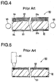
- Fig. 4 is a fragmentary enlarged sectional view of a light conductive plate type light source for which a conventional method of producing the light conductive plate type light source by using double-sided adhesive tapes is employed.
- Fig. 5 is a fragmentary enlarged sectional view of a light conductive plate type light source for which another conventional method of producing the light conductive plate type light source by operating an ultrasonic welding machine is employed.
- reference numeral 1 designates a light conductive plate type light source for which a method of producing the light conductive plate type light source in accordance with the embodiment of the present invention is employed.
- a light diffusing plate 3 prepared in the form of a sheet-shaped member is secured to a light conductive plate 2 on a front surface 2a side of the latter, while a light reflecting plate 4 is secured to the light conductive plate 2 on a rear surface 2b side of the latter.
- a characterizing feature of the present invention consists in that a plurality of fixing members 5 are used for securing the light diffusing plate 3 to the front surface 2a of the light conductive plate 2 and/or for securing the light reflecting plate 4 to the rear surface 2b of the light conductive plate 2. It is preferable from the viewpoint of easy handling as well as purchasing at an inexpensive cost that a plurality of hollow rivets each made of a metallic material and commercially available as a so-called eyelet rivet are used for the fixing members 5.
- the light diffusing plate 3 (or the light reflecting plate 4) is placed on the light conductive plate 2 in the overlapped state at a predetermined position relative to the light conductive plate 2.
- the three light diffusing plates 3a to 3c are used in place of a single light diffusing plate 3, it is obvious that the three diffusing plates 3a to 3c should simultaneously be placed on the front surface 2a of the light conductive plate 2 in the overlapped state.
- a plurality of fixing members 5 are press-fitted into the light conductive plate 2 through the light diffusing plate 3 (or through the light reflecting plate 4) at adequately predetermined positions.
- Each press fitting is achieved by applying ultrasonic waves to each fixing member 5, causing the latter to vibrate so as to allow the light conductive plate 2, the light diffusing plate 3 and the light reflecting plate 4 to be fused together in the presence of the frictional heat induced by ultrasonic vibration of the fixing members 5.
- a currently available ultrasonic welding machine having an output of 450 W was employed as an ultrasonic generating source.
- the fixing members 5 were successively press-fitted in the light conductive plate 2 with the aid of a horn 21 of the ultrasonic welding machine without any necessity for preliminarily forming holes through the light diffusing plate 3 and the light reflecting plate 4 as well as holes in the light conductive plate 2 so that the fitting members 5 passed through the light diffusing plate 3 and the light reflecting plate 4, and subsequently, they were embedded in the light conductive plate 2. It was found that each press-fitting operation was not adversely affected by the number of light diffusing plates 3 and each light diffusing plate 3 having a comparatively small thickness was not deformed in the shape of wrinkle, warpage or the like on completion of each press-fitting operation.
- the fixing members 5 were firmly held in the light conductive plate 2 with their foot portions 5a when the molten part of the light conductive plate 2 was solidified.
- the light diffusing plate 3 was firmly retained on the light conductive plate 2 with radially expanded flange portions 5b of the fixing members 5.
- a polyethylene terephthalate resin originally unable to be welded to the light conductive plate 3 made of an acrylic resin is employed as a material for the light diffusing plate 3
- both the light conductive plate 2 and the light diffusing plate 3 can reliably be fixedly secured to each other.
- the method of the present invention assures that a light conductive plate type light source can be produced at a very high yielding rate.
- a repairing operation is required due to, e.g., physical failure of the light diffusing plate 3 itself.
- the repairing operation is achieved by by removing the light diffusing plate 3 from the light conductive plate 2 and then exchanging the light diffusing plate 3 with a new one.
- Fig. 3 shows by way of fragmentary enlarged sectional view a step of removing the light diffusing plate 3 from the light conductive plate 2 for performing a repairing operation.
- steps of removing and exchanging cutting blades of a drill 22 are brought in contact with the head part of each fixing member 5 and then rotated to remove the radially expanded flange portion 5b of each fixing member 5 from a main body of the latter.
- the light diffusing plate 3 can easily be removed from the light conductive plate 3 in order to exchange the light diffusing plate 3 with a new one.
- eyelet-shaped hollow rivets each having a radially expanded flange portion are used for the fixing members 5.
- the present invention should not be limited only to the eyelet-shaped hollow rivets.
- staple-shaped fixing members each formed by bending a wire to exhibit a substantially inverted U-shaped contour may be substituted for the eyelet-shaped hollow rivets.
- nail-shaped fixing members may be substituted for the eyelet-shaped hollow rivets.
Landscapes
- Engineering & Computer Science (AREA)
- Mechanical Engineering (AREA)
- Physics & Mathematics (AREA)
- Manufacturing & Machinery (AREA)
- General Physics & Mathematics (AREA)
- Optics & Photonics (AREA)
- Planar Illumination Modules (AREA)
- Liquid Crystal (AREA)
- Lining Or Joining Of Plastics Or The Like (AREA)
- Light Guides In General And Applications Therefor (AREA)
Description
- The present invention relates generally to a method of producing a light conductive plate type light source. More particularly, the present invention relates to a method of producing a light conductive plate type light source preferably employable as a back light source for a liquid crystal display unit which is widely used as a display section for a television, an office automation equipment or the like at present.
- EP-A-392 863 discloses a light conductive plate type light source which comprises a light diffusing plate, a light conductive plate, and a light reflective plate. These three plates are secured together by two holders, each one having the shape of a U-shaped bar.
- To facilitate understanding of the present invention, a conventional method of producing a light conductive plate type light source of the foregoing type will be described below with reference to Fig. 4.
- Fig. 4 shows by way of fragmentary enlarged sectional view the structure of a light conductive plate
type light source 90 produced by employing the conventional method. As is apparent from the drawing, the light conductive platetype light source 90 includes a lightconductive plate 91 which is formed of a high transparent material such as an acrylic resin, and at least one sheet-shapedlight diffusing plate 92 is secured to the lightconductive plate 91 on afront surface 91a side while coming in substantially close contact with the lightconductive plate 91 so as to allow a light beam to be emitted from thefront surface 91a of the lightconductive plate 91 with excellent uniformity, while a sheet-shapedlight reflecting plate 93 is secured to the lightconductive plate 91 on arear surface 91b side of the lightconductive plate 91 in order to improve a lighting efficiency of the light conductive platetype light source 90. - The light
conductive plate 91 and the light diffusing plate 92 (or the light reflecting plate 93) are adhesively secured to each other with double-sidedadhesive tapes 94 interposed therebetween. In the case that a plurality of light diffusingplates 92 are used for the light conductive platetype light source 90 in order to improve a light diffusing property of the latter, the same securing operation to be achieved using double-sidedadhesive tapes 94 as mentioned above is repeated to build a laminated structure with the light diffusingplates 92. - Next, another conventional method of producing a light conductive plate type light source will be described below with reference to Fig. 5.
- Fig. 5 shows by way of fragmentary enlarged sectional view the state that three light diffusing
plates 92 are placed on a lightconductive plate 91 in the overlapped state at a predetermined position relative to the lightconductive plate 91, and while this overlapped state is maintained, both the lightconductive plate 91 and thelight dispersing plates 92 are welded together by operating an ultrasonic welding machine 80 from thelight diffusing plate 92 side without any use of double-sided adhesive tape. At this time, in the case that a plurality of light diffusingplates 92 are used for the light conductive platetype light source 90, there rises an occasion that a welding operation is completed merely by way of a single step. In practice, since it is very difficult that a plurality of light diffusingplates 92 are welded together without any fluctuation in strength, thelight diffusing plates 92 are usually welded together one by one in such a manner that a subsequentlight diffusing plate 92 is welded to the preceding light diffusing plate which has been already welded to the underlying light diffusing plate. - However, the above-described conventional methods have the following problems. Since both-sided
adhesive tapes 94 are used for achieving each securing operation, an extra quantity of adhesive is liable of flowing outside of the laminated structure. For this reason, it is required that each securing operation is carefully performed. This leads to a problem that a securing operation is achieved for the light conductive platetype light source 90 at an increased cost. Other problem is that a gap substantially equal to a thickness of the double-sidedadhesive tape 94 arises between the lightconductive plate 91 and thelight diffusing plate 92, causing thelight diffusing plate 92 to ha concavely warped, resulting in a quality of appearance of the light conductive platetype light source 90 being degraded. Another problem is that when a repairing operation is required after completion of a incorrect securing operation, an adhesive remaining on the double-sidedadhesive tape 94 should be removed from the lightconductive plate 91 while consuming a long time and many manhours. - In the case that an ultrasonic welding machine is employed for achieving each securing operation, it is necessary that a material constituting the light
conductive plate 91 and a material constituting thelight diffusing plate 92 can be welded to each other. Since a polyethylene terephthalate resin having an excellent light diffusing property, i.e., a typical material employable for thelight diffusing plate 92, can not be welded to the material constituting the lightconductive plate 91, there arises a problem that the kinds of materials employable for the light conductive plate, thelight diffusing plate 92, and the light reflecting plate are limitatively determined. Once the lightconductive plate 91 and the lightdiffusing plate 92 are welded to each other, it is impossible to perform a repairing operation for the light conductive platetype light source 90. In addition, as the number of light diffusingplates 92 increases, manhours required for achieving a securing operation proportionally increases regardless of the type of method employed for weldably securing both the lightconductive plate 91 and thelight scattering plates 92 together. Thus, there arises a problem that the light conductive platetype light source 90 having a plurality of light diffusing plates is produced at an increased cost. - The present invention has been made in consideration of the aforementioned background.
- An object of the present invention is to provide a method of producing a light conductive plate type light source wherein the method can be practiced at a reduced cost because no double-sided adhesive tape is required and no ultrasonic welding operation is performed for placing at least one light diffusing plate and a light reflecting plate on a light conductive plate in the overlapped state.
- Another object of the present invention is to provide a method of producing a light conductive type light source wherein the method can be practiced at a high efficiency because a plurality of light diffusing plates can simultaneously be press-fitted to the light conductive plate regardless of the number of light diffusing plates to be placed on the light conductive plate in the overlapped state.
- The present invention provides a light conductive plate type light source wherein at least one light diffusing plate and a light reflecting plate each prepared in the form of a sheet-shaped member are secured to the opposite illuminating surfaces of a light conductive plate while coming in substantially close contact with them, wherein the method comprises the steps of placing the light diffusing plate and the light reflecting plate on the opposite illuminating surfaces of the light conductive plate in the overlapped state at a predetermined position relative to the light conductive plate, and press-fitting a plurality of fixing members into the light conductive plate through the light diffusing plate and/or through the light reflecting plate with the aid of ultrasonic vibration applied to each fixing member.
- It is preferable from the viewpoint of a reduced production cost that the ultrasonic vibration is induced by an ultrasonic welding machine.
- Usually, a plurality of light diffusing plates are placed on the front illuminating surface of the light conductive plate in the overlapped state.
- It is preferable from the viewpoint of reliable press-fitting that each of the fixing members is prepared in the form of an eyelet-shaped hollow rivet made of a metallic material and having a radially expanded retaining flange portion.
- Alternatively, each fixing member may be prepared in the form of a staple-shaped fixing member which is formed by bending a wire to exhibit a substantially inverted U-shaped contour.
- Otherwise, each fixing member may be prepared in the form of a nail-shaped fixing member.
- With such construction as mentioned above, in the case that a plurality of light diffusing plates are placed on the light conductive plate in the overlapped state, it is possible to simultaneously press-fit them to the light conductive plate, resulting in a securing operation being achieved for the light conductive plate type light source at a remarkably improved efficiency compared with the conventional method wherein a plurality of light diffusing plates are fixedly secured to the light conductive plate one by one. Consequently, the light conductive plate type light source can produced at a reduced cost.
- Since the light diffusion plates and the light reflecting plate are fixedly secured to the light conductive plate using a plurality of fixing members, there does not arise a necessity for taking account of weldability or adhesiveness between the light conductive plate and the light diffusing plate, it is possible to select an optimum material for each of the light conductive plate and the light diffusing plate as desired. This leads to the result that performances of the light conductive plate type light source can be improved.
- In addition, in contrast with the conventional method wherein the light conductive plate and the light diffusion plate are fixedly secured to each other by using double-sided adhesive tapes or by simultaneously welding them together, the method of the present invention assures that the light conductive plate type light source exhibit excellent durability at an elevated temperature, resulting in reliability of the light conductive plate type light source being improved.
- Other objects, features and advantages of the present invention will become apparent from reading of the following description which has been made in conjunction with the accompanying drawings.
- Fig. 1 is a fragmentary enlarged sectional view of a light conductive plate type light source in the completely assembled state wherein a method of producing the light conductive plate type light source in accordance with an embodiment of the present invention is employed.
- Fig. 2 is a fragmentary enlarged sectional view of the light conductive plate type light source, showing a working step of fitting a fixing member into a light conductive plate according to the present invention.
- Fig. 3 is a fragmentary enlarged sectional view of the light conductive plate type light source, showing a step of cutting a part of the fixing member for removing light diffusing plates from the light conductive plate according to the present invention.
- Fig. 4 is a fragmentary enlarged sectional view of a light conductive plate type light source for which a conventional method of producing the light conductive plate type light source by using double-sided adhesive tapes is employed.
- Fig. 5 is a fragmentary enlarged sectional view of a light conductive plate type light source for which another conventional method of producing the light conductive plate type light source by operating an ultrasonic welding machine is employed.
- The present invention will now be described in detail hereinafter with reference to Fig. 1 to Fig. 3 which illustrate a preferred embodiment thereof.
- In Fig. 1, reference numeral 1 designates a light conductive plate type light source for which a method of producing the light conductive plate type light source in accordance with the embodiment of the present invention is employed. A
light diffusing plate 3 prepared in the form of a sheet-shaped member is secured to a lightconductive plate 2 on afront surface 2a side of the latter, while a light reflecting plate 4 is secured to the lightconductive plate 2 on arear surface 2b side of the latter. - A characterizing feature of the present invention consists in that a plurality of fixing members 5 are used for securing the
light diffusing plate 3 to thefront surface 2a of the lightconductive plate 2 and/or for securing the light reflecting plate 4 to therear surface 2b of the lightconductive plate 2. It is preferable from the viewpoint of easy handling as well as purchasing at an inexpensive cost that a plurality of hollow rivets each made of a metallic material and commercially available as a so-called eyelet rivet are used for the fixing members 5. - A procedure of securing the light diffusing plate 3 (or the light reflecting plate 4) to the
surface 2a (or 2b) of the lightconductive plate 2 using the fixing members 5 will be described below. - First, as shown in Fig. 2, the light diffusing plate 3 (or the light reflecting plate 4) is placed on the light
conductive plate 2 in the overlapped state at a predetermined position relative to the lightconductive plate 2. Provided that e.g., three light diffusingplates 3a to 3c are used in place of a singlelight diffusing plate 3, it is obvious that the threediffusing plates 3a to 3c should simultaneously be placed on thefront surface 2a of the lightconductive plate 2 in the overlapped state. - After the light diffusing plate 3 (or the light reflecting plate 4) is placed on the
surface 2a (or 2b) of the lightconductive plate 2 in the overlapped state at a predetermined position relative to the lightconductive plate 2, a plurality of fixing members 5 are press-fitted into the lightconductive plate 2 through the light diffusing plate 3 (or through the light reflecting plate 4) at adequately predetermined positions. Each press fitting is achieved by applying ultrasonic waves to each fixing member 5, causing the latter to vibrate so as to allow the lightconductive plate 2, thelight diffusing plate 3 and the light reflecting plate 4 to be fused together in the presence of the frictional heat induced by ultrasonic vibration of the fixing members 5. - To confirm effectiveness of the method of the present invention, the inventor conducted a series of experiments, and the results derived from these experiments are noted below.
- A currently available ultrasonic welding machine having an output of 450 W was employed as an ultrasonic generating source. In operation, the fixing members 5 were successively press-fitted in the light
conductive plate 2 with the aid of ahorn 21 of the ultrasonic welding machine without any necessity for preliminarily forming holes through thelight diffusing plate 3 and the light reflecting plate 4 as well as holes in the lightconductive plate 2 so that the fitting members 5 passed through thelight diffusing plate 3 and the light reflecting plate 4, and subsequently, they were embedded in the lightconductive plate 2. It was found that each press-fitting operation was not adversely affected by the number of light diffusingplates 3 and eachlight diffusing plate 3 having a comparatively small thickness was not deformed in the shape of wrinkle, warpage or the like on completion of each press-fitting operation. - After completion of the squeezing operation, it was confirmed that the fixing members 5 were firmly held in the light
conductive plate 2 with theirfoot portions 5a when the molten part of the lightconductive plate 2 was solidified. In addition, thelight diffusing plate 3 was firmly retained on the lightconductive plate 2 with radially expandedflange portions 5b of the fixing members 5. Thus, in the case that e.g., a polyethylene terephthalate resin originally unable to be welded to the lightconductive plate 3 made of an acrylic resin is employed as a material for thelight diffusing plate 3, both the lightconductive plate 2 and thelight diffusing plate 3 can reliably be fixedly secured to each other. - As is apparent from the above description, in contrast with the conventional methods, the method of the present invention assures that a light conductive plate type light source can be produced at a very high yielding rate. However, there arises an occasion that a repairing operation is required due to, e.g., physical failure of the
light diffusing plate 3 itself. At this time, it is recommandable that the repairing operation is achieved by by removing thelight diffusing plate 3 from the lightconductive plate 2 and then exchanging thelight diffusing plate 3 with a new one. - Fig. 3 shows by way of fragmentary enlarged sectional view a step of removing the
light diffusing plate 3 from the lightconductive plate 2 for performing a repairing operation. To execute steps of removing and exchanging, cutting blades of adrill 22 are brought in contact with the head part of each fixing member 5 and then rotated to remove the radially expandedflange portion 5b of each fixing member 5 from a main body of the latter. On completion of the cutting operation, thelight diffusing plate 3 can easily be removed from the lightconductive plate 3 in order to exchange thelight diffusing plate 3 with a new one. - In this embodiment, eyelet-shaped hollow rivets each having a radially expanded flange portion are used for the fixing members 5. However, the present invention should not be limited only to the eyelet-shaped hollow rivets. Alternatively, staple-shaped fixing members each formed by bending a wire to exhibit a substantially inverted U-shaped contour may be substituted for the eyelet-shaped hollow rivets. Otherwise, nail-shaped fixing members may be substituted for the eyelet-shaped hollow rivets. Provided that it is assured that the
light diffusing plate 2 can reliably be secured to the light conductive plate 3 (or the light reflecting plate 4), any type of fixing member is acceptable. - While the present invention has been described above with respect to a single preferred embodiment thereof, it should of course be understood that the present invention should not be limited only to this embodiment but various change or modification may be made without any departure from the scope of the present invention as defined by the appended claims.
Claims (7)
- A method of producing a light conductive plate type light source (1) wherein at least one light diffusing plate (3) and a light reflecting plate (4) each prepared in the form of a sheet-shaped member are secured to the opposite illuminating surfaces (2a, 2b) of a light conductive plate (2) while coming in substantially close contact with them, comprising the steps of;placing said light diffusing plate (3) and said light reflecting plate (4) on the opposite illuminating surfaces (2a, 2b) of said light conductive plate (2) in the overlapped state at a predetermined position relative to said light conductive plate (2), andpress-fitting a plurality of fixing members (5) to said light conductive plate (2) through said light diffusing plate (3) and/or through said light reflecting plate (3) with the aid of ultrasonic vibration applied to each fixing member (5).
- The method as claimed in claim 1, wherein said ultrasonic vibration is induced by an ultrasonic welding machine (21).
- The method as claimed in claim 1, wherein a plurality of light diffusing plates (3a, 3b, 3c) are placed on the front illuminating surface of said light conductive plate (2) in the overlapped state.
- The method as claimed in claim 1, wherein three light diffusing plates (3a, 3b, 3c) are placed on the front illuminating surface of said light conductive plate (2) in the overlapped state.
- The method as claimed in claim 1, wherein each of said fixing members (5) is an eyelet-shaped hollow rivet made of a metallic material and having a radially expanded retaining flange portion.
- The method as claimed in claim 1, wherein each of said fixing members (5) is a staple-shaped fixing member which is formed by bending a wire to exhibit a substantially inverted U-shaped contour.
- The method as claimed in claim 1, wherein each of said fixing members (5) is a nail-shaped fixing member.
Applications Claiming Priority (2)
| Application Number | Priority Date | Filing Date | Title |
|---|---|---|---|
| JP193888/93 | 1993-07-12 | ||
| JP5193888A JP2577303B2 (en) | 1993-07-12 | 1993-07-12 | Manufacturing method of light guide plate type light source |
Publications (3)
| Publication Number | Publication Date |
|---|---|
| EP0634675A2 EP0634675A2 (en) | 1995-01-18 |
| EP0634675A3 EP0634675A3 (en) | 1995-02-22 |
| EP0634675B1 true EP0634675B1 (en) | 1997-08-27 |
Family
ID=16315411
Family Applications (1)
| Application Number | Title | Priority Date | Filing Date |
|---|---|---|---|
| EP94110710A Expired - Lifetime EP0634675B1 (en) | 1993-07-12 | 1994-07-09 | Method of producing a light conductive plate type light source |
Country Status (5)
| Country | Link |
|---|---|
| US (1) | US5446627A (en) |
| EP (1) | EP0634675B1 (en) |
| JP (1) | JP2577303B2 (en) |
| KR (1) | KR100218159B1 (en) |
| DE (1) | DE69405175T2 (en) |
Families Citing this family (12)
| Publication number | Priority date | Publication date | Assignee | Title |
|---|---|---|---|---|
| JP3835770B2 (en) * | 1996-03-29 | 2006-10-18 | 株式会社エンプラス | Surface light source device |
| US6628431B1 (en) * | 1997-03-12 | 2003-09-30 | Pfu Limited | Picture readers and method for controlling the same |
| US7173677B2 (en) * | 2001-04-12 | 2007-02-06 | Rohm Co., Ltd. | Back light unit for liquid crystal display device and method for manufacturing the unit |
| US7236217B2 (en) * | 2003-01-16 | 2007-06-26 | 3M Innovative Properties Company | Package of optical films with zero-gap bond outside viewing area |
| JP4014526B2 (en) | 2003-03-20 | 2007-11-28 | 大日本印刷株式会社 | Fresnel lens sheet mounting structure and rear projection display device |
| US7413336B2 (en) | 2003-08-29 | 2008-08-19 | 3M Innovative Properties Company | Adhesive stacking for multiple optical films |
| US7339635B2 (en) | 2005-01-14 | 2008-03-04 | 3M Innovative Properties Company | Pre-stacked optical films with adhesive layer |
| JP2007076069A (en) * | 2005-09-12 | 2007-03-29 | Fujifilm Corp | Manufacturing method of optical sheet for display |
| US7777832B2 (en) | 2005-11-18 | 2010-08-17 | 3M Innovative Properties Company | Multi-function enhancement film |
| JP5499436B2 (en) * | 2007-12-25 | 2014-05-21 | 凸版印刷株式会社 | Light guide plate, backlight unit, and display device |
| JP2013252648A (en) * | 2012-06-06 | 2013-12-19 | Fukui Byora Co Ltd | Fastening method |
| WO2017005722A1 (en) * | 2015-07-09 | 2017-01-12 | Woodwelding Ag | Bonding objects together |
Family Cites Families (5)
| Publication number | Priority date | Publication date | Assignee | Title |
|---|---|---|---|---|
| US4775222A (en) * | 1984-08-27 | 1988-10-04 | Mitsubishi Rayon Company Ltd. | Light diffusing device |
| JP2538667B2 (en) * | 1989-04-13 | 1996-09-25 | 富士通株式会社 | Backlight |
| GB2240636B (en) * | 1990-01-31 | 1993-10-27 | Michael John Hort | Flexible light emitting elements |
| GB2249814B (en) * | 1990-08-16 | 1994-11-16 | Rawson Francis F H | Securing together plastic bodies |
| JP2640578B2 (en) * | 1991-02-27 | 1997-08-13 | シャープ株式会社 | LCD lighting system |
-
1993
- 1993-07-12 JP JP5193888A patent/JP2577303B2/en not_active Expired - Lifetime
-
1994
- 1994-07-09 DE DE69405175T patent/DE69405175T2/en not_active Expired - Fee Related
- 1994-07-09 EP EP94110710A patent/EP0634675B1/en not_active Expired - Lifetime
- 1994-07-11 US US08/273,380 patent/US5446627A/en not_active Expired - Fee Related
- 1994-07-12 KR KR1019940016776A patent/KR100218159B1/en not_active Expired - Fee Related
Also Published As
| Publication number | Publication date |
|---|---|
| EP0634675A3 (en) | 1995-02-22 |
| DE69405175T2 (en) | 1998-03-12 |
| JPH0743713A (en) | 1995-02-14 |
| JP2577303B2 (en) | 1997-01-29 |
| EP0634675A2 (en) | 1995-01-18 |
| DE69405175D1 (en) | 1997-10-02 |
| KR100218159B1 (en) | 1999-09-01 |
| US5446627A (en) | 1995-08-29 |
Similar Documents
| Publication | Publication Date | Title |
|---|---|---|
| US5446627A (en) | Method of producing a light conductive plate type light source | |
| US7307674B2 (en) | Back light unit for liquid crystal display device and method for manufacturing the unit | |
| US20100045888A1 (en) | Optical sheet retaining tool and chassis for liquid crystal display device | |
| US5729310A (en) | Lighting apparatus | |
| JP2003066301A (en) | Lens and lens holder joining structure and joining method | |
| CN106476291B (en) | The joint method and multi-part component of multiple components | |
| US20050284851A1 (en) | Method and apparatus for manufacturing vehicle lamps | |
| JP3072752B2 (en) | Manufacturing method of surface emitting device | |
| US7637644B2 (en) | Vehicle lamp housing and cover with welding surface structure | |
| JPH1099982A (en) | Laser welding method | |
| JP2530775B2 (en) | Honeycomb panel and method for manufacturing honeycomb panel | |
| JPH03223707A (en) | lens barrel | |
| JP2002318386A (en) | Structure of backlight device for liquid crystal display element and method of manufacturing the same | |
| JPH02312101A (en) | Assembly method of plate-shaped member molded light fixture | |
| JPH031382A (en) | Manufacture of recording disk | |
| CN218546995U (en) | Laser radar transmitter and laser radar | |
| JPS62267125A (en) | How to bond resin lenses and reflectors | |
| JPH06316009A (en) | Honeycomb panel and method for manufacturing honeycomb panel | |
| JPH0327598A (en) | Thin electronic apparatus and manufacture thereof | |
| JPH0743466B2 (en) | Polygon mirror and manufacturing method thereof | |
| JP3118297B2 (en) | Card with integrated circuit | |
| JP7040530B2 (en) | Manufacturing method of optical connector | |
| JPH01284492A (en) | Method of joining aluminum member | |
| KR0170264B1 (en) | Multi Vision Screen Bonding Device | |
| JP3431254B2 (en) | Component transport jig and component transport method using the same |
Legal Events
| Date | Code | Title | Description |
|---|---|---|---|
| PUAI | Public reference made under article 153(3) epc to a published international application that has entered the european phase |
Free format text: ORIGINAL CODE: 0009012 |
|
| PUAL | Search report despatched |
Free format text: ORIGINAL CODE: 0009013 |
|
| AK | Designated contracting states |
Kind code of ref document: A2 Designated state(s): DE GB |
|
| AK | Designated contracting states |
Kind code of ref document: A3 Designated state(s): DE GB |
|
| 17P | Request for examination filed |
Effective date: 19950330 |
|
| GRAG | Despatch of communication of intention to grant |
Free format text: ORIGINAL CODE: EPIDOS AGRA |
|
| 17Q | First examination report despatched |
Effective date: 19961204 |
|
| GRAH | Despatch of communication of intention to grant a patent |
Free format text: ORIGINAL CODE: EPIDOS IGRA |
|
| GRAH | Despatch of communication of intention to grant a patent |
Free format text: ORIGINAL CODE: EPIDOS IGRA |
|
| GRAA | (expected) grant |
Free format text: ORIGINAL CODE: 0009210 |
|
| AK | Designated contracting states |
Kind code of ref document: B1 Designated state(s): DE GB |
|
| REF | Corresponds to: |
Ref document number: 69405175 Country of ref document: DE Date of ref document: 19971002 |
|
| PLBE | No opposition filed within time limit |
Free format text: ORIGINAL CODE: 0009261 |
|
| STAA | Information on the status of an ep patent application or granted ep patent |
Free format text: STATUS: NO OPPOSITION FILED WITHIN TIME LIMIT |
|
| 26N | No opposition filed | ||
| PGFP | Annual fee paid to national office [announced via postgrant information from national office to epo] |
Ref country code: DE Payment date: 19990701 Year of fee payment: 6 |
|
| PGFP | Annual fee paid to national office [announced via postgrant information from national office to epo] |
Ref country code: GB Payment date: 19990705 Year of fee payment: 6 |
|
| PG25 | Lapsed in a contracting state [announced via postgrant information from national office to epo] |
Ref country code: GB Free format text: LAPSE BECAUSE OF NON-PAYMENT OF DUE FEES Effective date: 20000709 |
|
| GBPC | Gb: european patent ceased through non-payment of renewal fee |
Effective date: 20000709 |
|
| PG25 | Lapsed in a contracting state [announced via postgrant information from national office to epo] |
Ref country code: DE Free format text: LAPSE BECAUSE OF NON-PAYMENT OF DUE FEES Effective date: 20010501 |