EP0634580B1 - Plate assembly and assembling method - Google Patents
Plate assembly and assembling method Download PDFInfo
- Publication number
- EP0634580B1 EP0634580B1 EP93202055A EP93202055A EP0634580B1 EP 0634580 B1 EP0634580 B1 EP 0634580B1 EP 93202055 A EP93202055 A EP 93202055A EP 93202055 A EP93202055 A EP 93202055A EP 0634580 B1 EP0634580 B1 EP 0634580B1
- Authority
- EP
- European Patent Office
- Prior art keywords
- panel
- tab
- assembly according
- panels
- edge
- Prior art date
- Legal status (The legal status is an assumption and is not a legal conclusion. Google has not performed a legal analysis and makes no representation as to the accuracy of the status listed.)
- Expired - Lifetime
Links
Images




Classifications
-
- A—HUMAN NECESSITIES
- A47—FURNITURE; DOMESTIC ARTICLES OR APPLIANCES; COFFEE MILLS; SPICE MILLS; SUCTION CLEANERS IN GENERAL
- A47B—TABLES; DESKS; OFFICE FURNITURE; CABINETS; DRAWERS; GENERAL DETAILS OF FURNITURE
- A47B57/00—Cabinets, racks or shelf units, characterised by features for adjusting shelves or partitions
- A47B57/06—Cabinets, racks or shelf units, characterised by features for adjusting shelves or partitions with means for adjusting the height of the shelves
- A47B57/18—Cabinets, racks or shelf units, characterised by features for adjusting shelves or partitions with means for adjusting the height of the shelves consisting of screwbolts as connecting members
-
- A—HUMAN NECESSITIES
- A47—FURNITURE; DOMESTIC ARTICLES OR APPLIANCES; COFFEE MILLS; SPICE MILLS; SUCTION CLEANERS IN GENERAL
- A47B—TABLES; DESKS; OFFICE FURNITURE; CABINETS; DRAWERS; GENERAL DETAILS OF FURNITURE
- A47B57/00—Cabinets, racks or shelf units, characterised by features for adjusting shelves or partitions
- A47B57/06—Cabinets, racks or shelf units, characterised by features for adjusting shelves or partitions with means for adjusting the height of the shelves
- A47B57/20—Cabinets, racks or shelf units, characterised by features for adjusting shelves or partitions with means for adjusting the height of the shelves consisting of tongues, pins or similar projecting means coacting with openings
-
- F—MECHANICAL ENGINEERING; LIGHTING; HEATING; WEAPONS; BLASTING
- F16—ENGINEERING ELEMENTS AND UNITS; GENERAL MEASURES FOR PRODUCING AND MAINTAINING EFFECTIVE FUNCTIONING OF MACHINES OR INSTALLATIONS; THERMAL INSULATION IN GENERAL
- F16B—DEVICES FOR FASTENING OR SECURING CONSTRUCTIONAL ELEMENTS OR MACHINE PARTS TOGETHER, e.g. NAILS, BOLTS, CIRCLIPS, CLAMPS, CLIPS OR WEDGES; JOINTS OR JOINTING
- F16B5/00—Joining sheets or plates, e.g. panels, to one another or to strips or bars parallel to them
- F16B5/0004—Joining sheets, plates or panels in abutting relationship
- F16B5/0008—Joining sheets, plates or panels in abutting relationship by moving the sheets, plates or panels substantially in their own plane, perpendicular to the abutting edge
- F16B5/0012—Joining sheets, plates or panels in abutting relationship by moving the sheets, plates or panels substantially in their own plane, perpendicular to the abutting edge a tongue on the edge of one sheet, plate or panel co-operating with a groove in the edge of another sheet, plate or panel
-
- F—MECHANICAL ENGINEERING; LIGHTING; HEATING; WEAPONS; BLASTING
- F16—ENGINEERING ELEMENTS AND UNITS; GENERAL MEASURES FOR PRODUCING AND MAINTAINING EFFECTIVE FUNCTIONING OF MACHINES OR INSTALLATIONS; THERMAL INSULATION IN GENERAL
- F16B—DEVICES FOR FASTENING OR SECURING CONSTRUCTIONAL ELEMENTS OR MACHINE PARTS TOGETHER, e.g. NAILS, BOLTS, CIRCLIPS, CLAMPS, CLIPS OR WEDGES; JOINTS OR JOINTING
- F16B2200/00—Constructional details of connections not covered for in other groups of this subclass
- F16B2200/10—Details of socket shapes
-
- Y—GENERAL TAGGING OF NEW TECHNOLOGICAL DEVELOPMENTS; GENERAL TAGGING OF CROSS-SECTIONAL TECHNOLOGIES SPANNING OVER SEVERAL SECTIONS OF THE IPC; TECHNICAL SUBJECTS COVERED BY FORMER USPC CROSS-REFERENCE ART COLLECTIONS [XRACs] AND DIGESTS
- Y10—TECHNICAL SUBJECTS COVERED BY FORMER USPC
- Y10T—TECHNICAL SUBJECTS COVERED BY FORMER US CLASSIFICATION
- Y10T29/00—Metal working
- Y10T29/49—Method of mechanical manufacture
- Y10T29/49826—Assembling or joining
- Y10T29/49895—Associating parts by use of aligning means [e.g., use of a drift pin or a "fixture"]
-
- Y—GENERAL TAGGING OF NEW TECHNOLOGICAL DEVELOPMENTS; GENERAL TAGGING OF CROSS-SECTIONAL TECHNOLOGIES SPANNING OVER SEVERAL SECTIONS OF THE IPC; TECHNICAL SUBJECTS COVERED BY FORMER USPC CROSS-REFERENCE ART COLLECTIONS [XRACs] AND DIGESTS
- Y10—TECHNICAL SUBJECTS COVERED BY FORMER USPC
- Y10T—TECHNICAL SUBJECTS COVERED BY FORMER US CLASSIFICATION
- Y10T29/00—Metal working
- Y10T29/49—Method of mechanical manufacture
- Y10T29/49826—Assembling or joining
- Y10T29/49895—Associating parts by use of aligning means [e.g., use of a drift pin or a "fixture"]
- Y10T29/49899—Associating parts by use of aligning means [e.g., use of a drift pin or a "fixture"] by multiple cooperating aligning means
-
- Y—GENERAL TAGGING OF NEW TECHNOLOGICAL DEVELOPMENTS; GENERAL TAGGING OF CROSS-SECTIONAL TECHNOLOGIES SPANNING OVER SEVERAL SECTIONS OF THE IPC; TECHNICAL SUBJECTS COVERED BY FORMER USPC CROSS-REFERENCE ART COLLECTIONS [XRACs] AND DIGESTS
- Y10—TECHNICAL SUBJECTS COVERED BY FORMER USPC
- Y10T—TECHNICAL SUBJECTS COVERED BY FORMER US CLASSIFICATION
- Y10T403/00—Joints and connections
- Y10T403/16—Joints and connections with adjunctive protector, broken parts retainer, repair, assembly or disassembly feature
- Y10T403/1616—Position or guide means
- Y10T403/1624—Related to joint component
Definitions
- This invention relates to a panel assembly and a mechanical assembling method used therefor, particularly suitable for application in apparatus.
- Most apparatus as e.g. a photographic camera, a processor for exposed materials, an optoelectronic scanner, a xerographic copier, a thermal printer, are mounted within a generally rectangular housing, which may include a rectangular metal frame for supporting various parts of the apparatus.
- the frame of the apparatus thus has to be designed and manufactured within rather small and robust tolerances, thereby minimising the creation of disturbing splits between said panels.
- the frame thus formed needs a geometry which requires no adjustment after it has been assembled and which is stable in time.
- US-A-4 535 704 discloses a panel assembly in which tabs on one panel extend through slots in the other panel, a shoulder at one side of each tab providing support.
- the present invention to provide an improved assembly of a first panel with another panel in a well defined geometrical relationship such that the distance between said panels is correct in at least one direction, and this without the use of supplementary positioning means, or of complicated machining.
- the improvement mainly consists in attaining a precise and stable geometry for said assembly by money saving manufacturing and mounting techniques.
- said second panel further is provided with at least one angled portion partially surrounding said projecting tab, and wherein said second panel is fixed to said first panel by fastening means engaging said angled portion and said first panel.
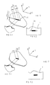
- Fig 1 a schematic side view of an apparatus with a frame comprising panels 1 and 2 which may suitably be steel plates or the like.
- a rectangular coordinate system having a X, a Y and a Z axis, a first panel 1 and a second panel 2.
- the first panel 1 has a slot 11 and a supporting plane 12.
- the second panel 2 has a projecting lip or tab 21 extending outwardly from one edge 22 thereof.
- the complementary shapes of panels 1 and 2 permit their assembly in an exact position and holding in position before their optional final fastening together by fastening means.
- the assembly evidently may be applied twice, namely at both ends of the horizontal panel 2, more specifically, once at he left side of panel 2 and once at the right side of panel 2. Further details will be explained in separate paragraphs and in reference to more detailed drawings.
- FIG. 3 illustrates a first embodiment of the present invention with an assembly of two panels 1 and 2, wherein panel 1 comprises at least one insertion slot 11 and the other panel 2 comprises at least one projecting tab 21 extending outwardly from one edge 22 thereof and fitting in said slot 11.
- projecting tab 21 has two shoulder edges 31 located between the end edge or "the top” 32 and the base 33 of tab 21, and panel 1 abuts by its supporting plane 12 on shoulder edge 31 of panel 2, as the projection tab 21 is pushed into the insertion slot 11.
- said one edge 22 of second panel 2 remains out of contact with said first panel 1.
- the height of the projecting tab 21, defined by the Z-distance between the top 32 and the base 33 of the tab 21, is equal to the height of the shoulder and the thickness of panel 1, so that it will be flush with the other side of panel 1.
- the end edge of said tab 21 may be chamfered or tapered (not shown).
- the "X-length” (representing the dimension in a direction according to the X axis) of opening 11 and the "Z-width” (representing the dimension in a direction according to the Z axis) of same opening 11 are not smaller as the respective X-length and Z-width of the corresponding tab(s) 21 (see clearances 34 in the X direction indicated in Figs. 3 and 6, and clearances 112 in the Z direction as indicated in Fig. 11).
- the prior state of the art usually bends an angled portion or a flange at the Y-directed edge 22 of panel 2. Said flange then generally serves to make an abutting contact between panels 1 and 2, when fastened by e.g. a bolt connection.
- the prior art bending of panel 2 in order to make said flange inherently causes bending tolerances, which are standardised in e.g. the german DIN 6930.
- the present invention does not use any bending for abutting panels 1 and 2, but mainly uses a punching or cutting operation with inherent punching tolerances.
- the disclosed assembly provides a simple construction which enables to be positioned in a predictable position, despite variations in the thicknesses of said panels.
- a panel 2 may have more than one tab 21. Especially if the panels 1 and 2 are rather great, it is often advantageous, in order to align both panels precisely over their total length, to use several sets of cooperating tabs and slots.
- Fig. 4 illustrates two tabs 43 and 44 lying substantially in a same plane of a second panel and a first panel 1 which accordingly comprises corresponding insertion slots 41 and 42.
- the crosssectional shape of said tab corresponds generally with the shape of said slot.
- said tab is located in the plane of said second panel 2.
- both cross-sections may have a rectangular or a non rectangular corresponding shape of which Fig. 5 gives an overview.
- Fig. 6 illustrates a further embodiment of the present invention.
- the slot width w s is punched with high precision and thus narrow width tolerances, so that the projecting tab 21 and the slot 11 may be fitted without any clearances in the Z direction.
- Fig. 7 illustrates a further embodiment of the present invention.
- both panels 1 and 2 are already cleared, at least in one direction as e.g. the Y direction, further attention is directed to the angular position of said both panels.
- At least one interconnection element for interconnecting panel 2 to panel 1 is proposed, which may be a separate interconnection element (possibly riveted onto panel 2) or which may be an integrated portion of panel 2. More practically, in Fig. 8, is illustrated a partial elevation of a panel 2 according to a preferred embodiment, provided with at least one said interconnection element, intended for later interconnecting panel 2 to panel 1.
- said interconnection element of panel 2 preferably is an integrated angled portion 24, partially surrounding said projecting tab 21, and laying slightly below the shoulder edge 31, e. g. some 0.3 mm, so that it does not make any contact with panel 1, at least as long as it is not fixed or secured by any fastening means (to be described further on).
- said second panel 2 comprises an outer spigot plane 81, an outer peripheral recess 82, an angled portion 24 connected to said second panel 2 by at least one tongue 83, an inner recess 84 and the already described projecting tab 21.
- the assembly according to the present invention preferably has said two panels 1 and 2 at a right angle ⁇ to each other.
- panel 2 comprises an angled portion 24 under a bending angle ⁇ for supporting first panel 1.
- the assembly further comprises at least one fastening means for securing said panels 1, 2 to each other and to inhibit relative movement of the plates (not shown separately).
- said fastening means may be removable, as e.g if formed by a bolt and a nut, by means of self tapping screws, by an anchorage with threads (defined in DIN 7952) or by a screw and a screw receptable (as defined earlier in the background of the invention).
- said fastening means may be not removable, as e.g.
- angled portion 24 is laying below the shoulder edge 31, so that it does not really make contact with the first panel 1 as long as panels 1 and 2 are just mounted without any fastening means.
- angled portion 24 may be pulled towards the first panel 1. Yet, this does not influence the relative Y distance, which is defined solely by the abutment of the shoulder edge 31 to the supporting plane of panel 1.
- said angled portion 24 clearly has to be bended towards panel 1, which my be provided by the pulling forces exerted by said removable or non removable fastening means. If the panel 2 would have a relative big thickness, such that bending of said angled portion 24 would be rather difficult, a solution may be given hereto by providing a proportionally small tongue 83 (see Fig. 8), which indeed does deform more easily.
- FIG. 10 shows an alternative assembly comprising a resilient material 101 and a fastening means 102.
- an assembly comprising a second panel with two tabs, one in a same plane of said second panel and one with an angled portion (not shown separately).
- Fig. 11 is illustrated an alternative assembly, wherein said panel 2 is provided with at least one angled portion 24, partially surrounding said projecting tab 21, laying rather far below the shoulder edge 31, e. g. some mm, for supporting said first panel 1 or even a third panel 111.
- the assembly generally further may comprise a supplementary fastening means 102 for securing at least two of said panels (1, 2 and 111) to each other.
- Such assembly as indicated by Fig. 11 may advantageously be applied in outside covering panels (e.g. referal 1) of an apparatus, whenever an operator does not want to be disturbed by any perceived fastening means, e.g. by esthetical reasons. This might be accomplished by mounting said fastening means 102 in a hidden panel 111.
- said angled portion 24 may have a bending angle ⁇ between 70° and 110°, preferably 90°.
- a combination may be made of Figs. 9 and 10, 9 and 11, 10 and 11 or 9, 10 and 11 (not shown separately).
- ⁇ perpendicular or not perpendicular as illustrated by Fig. 12.
- ⁇ perpendicular or not perpendicular
- Such embodiment with ⁇ being substantially not perpendicular may advantageously be applied in optical lightshafts, in papertrays, in inclined keypanels, etc.
- the use of two such separate assemblies with ⁇ intentionally being 90° also can replace the above mentioned high precision punching of panels 1 and 2 respecting all three dimensions X-Y-Z, as illustrated in Fig. 7.
- Fig. 13 comprising Figs. 13.1 and 13.2, shows some plan views of the second panel 2, both situated after punching, with or without a fastening hole 23, and before any possible bending is applied.
- panel 2 may have a first undercut or recess 131 to facilitate a precise shoulder and a second undercut or recess 132 to facilitate the bending of the angled portion 24.
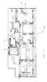
- Fig. 14 is a side view of a practical apparatus and incorporates many of the abovementioned assemblies, some of which now are recapitulated.
- the manufacturing of the plates in particular of the co-operating tabs and openings, can also be carried out by other techniques than punching or diestamping, e.g. by lasercutting.
- the final precision of the assembly will depend on the manufacturing tolerances of such other technique.
- said panels 1 and 2 are made from sheet steel which has been punched to obtain the correct tab and slot configurations. But, the same concept may be applied to some plastic materials (as e.g. tradenames Lexan, Makrolon and Perspex ).
- the punching or lasercutting operation may optionally be replaced by other manufacturing operations, such as injection moulding.
Landscapes
- Engineering & Computer Science (AREA)
- General Engineering & Computer Science (AREA)
- Mechanical Engineering (AREA)
- Connection Of Plates (AREA)
- Electrophotography Configuration And Component (AREA)
Description
The complementary shapes of
In order to attain a correct distance (indicated in Y-direction as yd in Fig. 1) between both vertical panels, the assembly evidently may be applied twice, namely at both ends of the
For a good understanding, it is understriked again that the present invention does not suffer from any bending tolerances. Herefrom it follows, that after assembling 1 and 2 together according to Fig. 6, as well their relative Y positions as well as their relative Z positions are very exact, even after several assemblings and dissasemblings.
If β is not 90°, any vertical position on the
In case a fastening means is introduced,
In order to make said contact, said
In the case illustrated by Fig. 11, the assembly generally further may comprise a supplementary fastening means 102 for securing at least two of said panels (1, 2 and 111) to each other. Such assembly as indicated by Fig. 11 may advantageously be applied in outside covering panels (e.g. referal 1) of an apparatus, whenever an operator does not want to be disturbed by any perceived fastening means, e.g. by esthetical reasons. This might be accomplished by mounting said fastening means 102 in a hidden
Z= M. cos|µ - 90°|and X= M. sin|µ - 90°|.
Claims (9)
- A panel assembly comprising a first panel (1), having at least one insertion slot (11), and a second panel (2) having at least one projecting tab (21) projecting outwardly from at least one edge (22) thereof to terminate in a free end (32) and fitting into said insertion slot, said one edge of the second panel being maintained out of contact with said first panel, said tab including shoulders (31) located between said free end of the tab and said one edge of said second panel, said shoulder defining a generally straight and perpendicular shoulder edge on each of two opposite sides of said projecting tab, which edge is in abutting contact with said first panel, said first panel having one face (12) in said abutment with said shoulder edges of said second panel and an opposite face remote from said shoulder edges, and said free end (32) of said projecting tab on said second panel is substantially flush with said opposite face of said second panel.
- An assembly according to claim 1, wherein the cross sectional shape of said projecting tab (21) corresponds generally with the shape of said insertion slot (11).
- An assembly according to claim 1 or 2, wherein said second panel has at least two projecting tabs (43, 44) lying substantially in a same plane and wherein said first panel has corresponding insertion slots (41, 42) therein for reception of said at least two tabs.
- An assembly according to any of the preceding claims, wherein said second panel (2) is provided with at least one interconnection element for mechanially attaching said second panel (2) to said first panel (1).
- An assembly according to claim 4, wherein said interconnection element comprises an angled portion (24) of said second panel (2) partially surrounding said projecting tab (21).
- An assembly according to claim 5, wherein said second panel (2) is attached to said first panel (1) by fastening means (102) engaging the angled portion (24) and said first panel (1).
- An assembly according to any of the preceding claims, wherein said panels (1, 2) are made from sheet metal which has been punched to obtain the correct tab and slot configurations.
- An assembly according to claim 6, wherein a portion of said second panel has been cut and bent out of the plane thereof to form said angled portion.
- An assembly according to claim 5, further comprising a resilient material (101) located between said first panel (1) and the angled portion (24) of said second panel (2).
Priority Applications (4)
| Application Number | Priority Date | Filing Date | Title |
|---|---|---|---|
| EP93202055A EP0634580B1 (en) | 1993-07-12 | 1993-07-12 | Plate assembly and assembling method |
| DE69316606T DE69316606T2 (en) | 1993-07-12 | 1993-07-12 | Connection arrangement between plates and connection method |
| US08/260,911 US5595454A (en) | 1993-07-12 | 1994-06-15 | Panel assembly |
| JP6177495A JPH0743969A (en) | 1993-07-12 | 1994-07-05 | Plate structure and assembling thereof |
Applications Claiming Priority (1)
| Application Number | Priority Date | Filing Date | Title |
|---|---|---|---|
| EP93202055A EP0634580B1 (en) | 1993-07-12 | 1993-07-12 | Plate assembly and assembling method |
Publications (2)
| Publication Number | Publication Date |
|---|---|
| EP0634580A1 EP0634580A1 (en) | 1995-01-18 |
| EP0634580B1 true EP0634580B1 (en) | 1998-01-21 |
Family
ID=8213985
Family Applications (1)
| Application Number | Title | Priority Date | Filing Date |
|---|---|---|---|
| EP93202055A Expired - Lifetime EP0634580B1 (en) | 1993-07-12 | 1993-07-12 | Plate assembly and assembling method |
Country Status (4)
| Country | Link |
|---|---|
| US (1) | US5595454A (en) |
| EP (1) | EP0634580B1 (en) |
| JP (1) | JPH0743969A (en) |
| DE (1) | DE69316606T2 (en) |
Families Citing this family (21)
| Publication number | Priority date | Publication date | Assignee | Title |
|---|---|---|---|---|
| US20040210289A1 (en) * | 2002-03-04 | 2004-10-21 | Xingwu Wang | Novel nanomagnetic particles |
| US20040254419A1 (en) * | 2003-04-08 | 2004-12-16 | Xingwu Wang | Therapeutic assembly |
| US20050025797A1 (en) * | 2003-04-08 | 2005-02-03 | Xingwu Wang | Medical device with low magnetic susceptibility |
| US20050155779A1 (en) * | 2003-04-08 | 2005-07-21 | Xingwu Wang | Coated substrate assembly |
| US20050261763A1 (en) * | 2003-04-08 | 2005-11-24 | Xingwu Wang | Medical device |
| US20050240100A1 (en) * | 2003-04-08 | 2005-10-27 | Xingwu Wang | MRI imageable medical device |
| US20050244337A1 (en) * | 2003-04-08 | 2005-11-03 | Xingwu Wang | Medical device with a marker |
| US20050278020A1 (en) * | 2003-04-08 | 2005-12-15 | Xingwu Wang | Medical device |
| US20050079132A1 (en) * | 2003-04-08 | 2005-04-14 | Xingwu Wang | Medical device with low magnetic susceptibility |
| US20070010702A1 (en) * | 2003-04-08 | 2007-01-11 | Xingwu Wang | Medical device with low magnetic susceptibility |
| US20070027532A1 (en) * | 2003-12-22 | 2007-02-01 | Xingwu Wang | Medical device |
| DE502005000294D1 (en) * | 2004-04-23 | 2007-02-22 | Sulzer Chemtech Ag | Fluid inlet device for an apparatus, in particular for a column |
| JP4124169B2 (en) * | 2004-06-21 | 2008-07-23 | 住友電装株式会社 | Body fixing structure of the protector |
| JP2008020854A (en) * | 2006-07-14 | 2008-01-31 | Murata Mach Ltd | Image forming apparatus and manufacturing method therefor |
| US20080216426A1 (en) * | 2007-03-09 | 2008-09-11 | Tuff Shed, Inc. | Building with Interlocking Panels |
| EP2130639A1 (en) * | 2008-06-04 | 2009-12-09 | Bystronic Laser AG | Laser cutting machine with protective plates |
| US8128307B2 (en) * | 2008-08-19 | 2012-03-06 | Xerox Corporation | Locking structure having threaded insert |
| US20140030017A1 (en) * | 2012-07-26 | 2014-01-30 | Shen Luo | Assembled furniture |
| CN103203732B (en) * | 2013-03-20 | 2015-07-22 | 沈阳飞机工业(集团)有限公司 | Method for designing slender part sample plate |
| US9411301B2 (en) * | 2014-01-31 | 2016-08-09 | Canon Kabushiki Kaisha | Frame for image forming apparatus and manufacturing method thereof |
| JP7035450B2 (en) * | 2017-10-27 | 2022-03-15 | 富士フイルムビジネスイノベーション株式会社 | Frame structure and image forming device |
Family Cites Families (12)
| Publication number | Priority date | Publication date | Assignee | Title |
|---|---|---|---|---|
| US3851222A (en) * | 1973-12-17 | 1974-11-26 | Gte Automatic Electric Lab Inc | Printed wiring card stiffener bracket |
| CH602209A5 (en) * | 1974-10-17 | 1978-07-31 | Bbc Brown Boveri & Cie | |
| US4535704A (en) * | 1983-09-06 | 1985-08-20 | The Mead Corporation | System of shelving |
| DE3335664A1 (en) * | 1983-09-30 | 1985-04-18 | Siemens AG, 1000 Berlin und 8000 München | Device for the protection of electrical assemblies and components which are contained in a housing against interference resulting from electrical charges and interference currents |
| US4648298A (en) * | 1985-05-20 | 1987-03-10 | Hero Automation | In-line shearing device |
| US4874148A (en) * | 1986-12-12 | 1989-10-17 | Newell Co. | Universal display bracket |
| JP2563471B2 (en) * | 1988-04-27 | 1996-12-11 | 松下電器産業株式会社 | Printed circuit board connection device |
| DE8805874U1 (en) * | 1988-05-03 | 1988-08-18 | Siemens AG, 1000 Berlin und 8000 München | Device for directly connecting boards arranged at right angles to each other |
| JPH036097A (en) * | 1989-06-02 | 1991-01-11 | Canon Inc | Circuit board mounting structure |
| JP2877878B2 (en) * | 1990-02-28 | 1999-04-05 | 日本ヒューレット・パッカード株式会社 | Printed circuit board holding pier and method of using the same |
| JPH0428300A (en) * | 1990-05-23 | 1992-01-30 | Matsushita Electric Ind Co Ltd | Electronic equipment |
| US5291376A (en) * | 1993-03-15 | 1994-03-01 | Texas Instruments Incorporated | System for coupling a high voltage, high current wire to a circuit board |
-
1993
- 1993-07-12 DE DE69316606T patent/DE69316606T2/en not_active Expired - Fee Related
- 1993-07-12 EP EP93202055A patent/EP0634580B1/en not_active Expired - Lifetime
-
1994
- 1994-06-15 US US08/260,911 patent/US5595454A/en not_active Expired - Fee Related
- 1994-07-05 JP JP6177495A patent/JPH0743969A/en active Pending
Also Published As
| Publication number | Publication date |
|---|---|
| US5595454A (en) | 1997-01-21 |
| JPH0743969A (en) | 1995-02-14 |
| DE69316606T2 (en) | 1998-08-27 |
| EP0634580A1 (en) | 1995-01-18 |
| DE69316606D1 (en) | 1998-02-26 |
Similar Documents
| Publication | Publication Date | Title |
|---|---|---|
| EP0634580A1 (en) | Plate assembly and assembling method | |
| US5259091A (en) | Hinge system for electrical enclosures | |
| JPH0820098B2 (en) | Duct connection system | |
| US5597259A (en) | Plate assembly | |
| US5722276A (en) | Method for attaching faceplate mounting tabs to a mortise lock housing and tabs and housings adapted for that method | |
| CA2122206C (en) | Trim mounting structure | |
| JPH0211802Y2 (en) | ||
| US5753859A (en) | Fitting structure for electrical connection box | |
| KR100405502B1 (en) | Device for fitting a front frame to a housing | |
| JP2000074020A (en) | Mounting equipment for member | |
| JPS641362Y2 (en) | ||
| JP2525264Y2 (en) | Fixture | |
| EP4475363A1 (en) | Frame for the fixing of electrical mechanisms and the like | |
| JPH045385B2 (en) | ||
| JPH0645023Y2 (en) | Hinge for glass doors such as product display cases | |
| JPH0140208Y2 (en) | ||
| JP2917801B2 (en) | Mounting structure between frame and supported member | |
| JPS6237296Y2 (en) | ||
| JPH0230980Y2 (en) | ||
| JPS6212752Y2 (en) | ||
| JPH0225894Y2 (en) | ||
| JPH0225266Y2 (en) | ||
| JPS6318673Y2 (en) | ||
| JPH094330A (en) | Door | |
| JPH0715173Y2 (en) | Exterior case structure |
Legal Events
| Date | Code | Title | Description |
|---|---|---|---|
| PUAI | Public reference made under article 153(3) epc to a published international application that has entered the european phase |
Free format text: ORIGINAL CODE: 0009012 |
|
| AK | Designated contracting states |
Kind code of ref document: A1 Designated state(s): BE DE FR GB NL |
|
| 17P | Request for examination filed |
Effective date: 19950718 |
|
| 17Q | First examination report despatched |
Effective date: 19960304 |
|
| GRAG | Despatch of communication of intention to grant |
Free format text: ORIGINAL CODE: EPIDOS AGRA |
|
| GRAG | Despatch of communication of intention to grant |
Free format text: ORIGINAL CODE: EPIDOS AGRA |
|
| GRAH | Despatch of communication of intention to grant a patent |
Free format text: ORIGINAL CODE: EPIDOS IGRA |
|
| GRAH | Despatch of communication of intention to grant a patent |
Free format text: ORIGINAL CODE: EPIDOS IGRA |
|
| GRAA | (expected) grant |
Free format text: ORIGINAL CODE: 0009210 |
|
| AK | Designated contracting states |
Kind code of ref document: B1 Designated state(s): BE DE FR GB NL |
|
| REF | Corresponds to: |
Ref document number: 69316606 Country of ref document: DE Date of ref document: 19980226 |
|
| ET | Fr: translation filed | ||
| PLBE | No opposition filed within time limit |
Free format text: ORIGINAL CODE: 0009261 |
|
| 26N | No opposition filed | ||
| PGFP | Annual fee paid to national office [announced via postgrant information from national office to epo] |
Ref country code: NL Payment date: 19990630 Year of fee payment: 7 |
|
| REG | Reference to a national code |
Ref country code: GB Ref legal event code: 746 Effective date: 20000821 |
|
| REG | Reference to a national code |
Ref country code: FR Ref legal event code: D6 |
|
| PG25 | Lapsed in a contracting state [announced via postgrant information from national office to epo] |
Ref country code: NL Free format text: LAPSE BECAUSE OF NON-PAYMENT OF DUE FEES Effective date: 20010201 |
|
| NLV4 | Nl: lapsed or anulled due to non-payment of the annual fee |
Effective date: 20010201 |
|
| REG | Reference to a national code |
Ref country code: GB Ref legal event code: IF02 |
|
| PGFP | Annual fee paid to national office [announced via postgrant information from national office to epo] |
Ref country code: DE Payment date: 20070621 Year of fee payment: 15 Ref country code: BE Payment date: 20070621 Year of fee payment: 15 |
|
| PGFP | Annual fee paid to national office [announced via postgrant information from national office to epo] |
Ref country code: GB Payment date: 20070621 Year of fee payment: 15 |
|
| PGFP | Annual fee paid to national office [announced via postgrant information from national office to epo] |
Ref country code: FR Payment date: 20070620 Year of fee payment: 15 |
|
| GBPC | Gb: european patent ceased through non-payment of renewal fee |
Effective date: 20080712 |
|
| PG25 | Lapsed in a contracting state [announced via postgrant information from national office to epo] |
Ref country code: DE Free format text: LAPSE BECAUSE OF NON-PAYMENT OF DUE FEES Effective date: 20090203 |
|
| REG | Reference to a national code |
Ref country code: FR Ref legal event code: ST Effective date: 20090331 |
|
| PG25 | Lapsed in a contracting state [announced via postgrant information from national office to epo] |
Ref country code: GB Free format text: LAPSE BECAUSE OF NON-PAYMENT OF DUE FEES Effective date: 20080712 |
|
| PG25 | Lapsed in a contracting state [announced via postgrant information from national office to epo] |
Ref country code: FR Free format text: LAPSE BECAUSE OF NON-PAYMENT OF DUE FEES Effective date: 20080731 |
|
| PG25 | Lapsed in a contracting state [announced via postgrant information from national office to epo] |
Ref country code: BE Free format text: LAPSE BECAUSE OF NON-PAYMENT OF DUE FEES Effective date: 20080731 |