EP0634064B1 - Synchronous-rectification type control for direct current motors - Google Patents
Synchronous-rectification type control for direct current motors Download PDFInfo
- Publication number
- EP0634064B1 EP0634064B1 EP93907706A EP93907706A EP0634064B1 EP 0634064 B1 EP0634064 B1 EP 0634064B1 EP 93907706 A EP93907706 A EP 93907706A EP 93907706 A EP93907706 A EP 93907706A EP 0634064 B1 EP0634064 B1 EP 0634064B1
- Authority
- EP
- European Patent Office
- Prior art keywords
- motor
- control
- field effect
- channel
- electronic control
- Prior art date
- Legal status (The legal status is an assumption and is not a legal conclusion. Google has not performed a legal analysis and makes no representation as to the accuracy of the status listed.)
- Expired - Lifetime
Links
- 239000002918 waste heat Substances 0.000 claims abstract description 8
- 238000012856 packing Methods 0.000 claims abstract description 5
- 230000005669 field effect Effects 0.000 claims description 21
- 239000003990 capacitor Substances 0.000 claims description 14
- 238000003780 insertion Methods 0.000 claims description 4
- 230000037431 insertion Effects 0.000 claims description 4
- 229910000639 Spring steel Inorganic materials 0.000 claims description 2
- 238000000034 method Methods 0.000 abstract description 16
- 238000010586 diagram Methods 0.000 description 7
- 230000001133 acceleration Effects 0.000 description 4
- 230000002035 prolonged effect Effects 0.000 description 4
- 230000004044 response Effects 0.000 description 4
- 241000282412 Homo Species 0.000 description 3
- XUIMIQQOPSSXEZ-UHFFFAOYSA-N Silicon Chemical compound [Si] XUIMIQQOPSSXEZ-UHFFFAOYSA-N 0.000 description 3
- 238000010438 heat treatment Methods 0.000 description 3
- 229910052710 silicon Inorganic materials 0.000 description 3
- 239000010703 silicon Substances 0.000 description 3
- 230000002459 sustained effect Effects 0.000 description 3
- 241000282414 Homo sapiens Species 0.000 description 2
- 238000010276 construction Methods 0.000 description 2
- 230000001419 dependent effect Effects 0.000 description 2
- 238000005553 drilling Methods 0.000 description 2
- 238000005265 energy consumption Methods 0.000 description 2
- 230000006870 function Effects 0.000 description 2
- 230000017525 heat dissipation Effects 0.000 description 2
- 230000020169 heat generation Effects 0.000 description 2
- 230000008569 process Effects 0.000 description 2
- 238000010079 rubber tapping Methods 0.000 description 2
- 239000004065 semiconductor Substances 0.000 description 2
- 230000008901 benefit Effects 0.000 description 1
- 239000000969 carrier Substances 0.000 description 1
- 230000008859 change Effects 0.000 description 1
- 239000004020 conductor Substances 0.000 description 1
- 230000003247 decreasing effect Effects 0.000 description 1
- 230000005611 electricity Effects 0.000 description 1
- 230000003090 exacerbative effect Effects 0.000 description 1
- 230000001939 inductive effect Effects 0.000 description 1
- 230000007257 malfunction Effects 0.000 description 1
- 238000004519 manufacturing process Methods 0.000 description 1
- 230000003071 parasitic effect Effects 0.000 description 1
- 230000021715 photosynthesis, light harvesting Effects 0.000 description 1
- 229920000642 polymer Polymers 0.000 description 1
- 230000002441 reversible effect Effects 0.000 description 1
- 238000005476 soldering Methods 0.000 description 1
- 239000007787 solid Substances 0.000 description 1
- 230000001052 transient effect Effects 0.000 description 1
- 238000004804 winding Methods 0.000 description 1
Images
Classifications
-
- H—ELECTRICITY
- H02—GENERATION; CONVERSION OR DISTRIBUTION OF ELECTRIC POWER
- H02P—CONTROL OR REGULATION OF ELECTRIC MOTORS, ELECTRIC GENERATORS OR DYNAMO-ELECTRIC CONVERTERS; CONTROLLING TRANSFORMERS, REACTORS OR CHOKE COILS
- H02P7/00—Arrangements for regulating or controlling the speed or torque of electric DC motors
- H02P7/06—Arrangements for regulating or controlling the speed or torque of electric DC motors for regulating or controlling an individual dc dynamo-electric motor by varying field or armature current
- H02P7/18—Arrangements for regulating or controlling the speed or torque of electric DC motors for regulating or controlling an individual dc dynamo-electric motor by varying field or armature current by master control with auxiliary power
- H02P7/24—Arrangements for regulating or controlling the speed or torque of electric DC motors for regulating or controlling an individual dc dynamo-electric motor by varying field or armature current by master control with auxiliary power using discharge tubes or semiconductor devices
- H02P7/28—Arrangements for regulating or controlling the speed or torque of electric DC motors for regulating or controlling an individual dc dynamo-electric motor by varying field or armature current by master control with auxiliary power using discharge tubes or semiconductor devices using semiconductor devices
- H02P7/285—Arrangements for regulating or controlling the speed or torque of electric DC motors for regulating or controlling an individual dc dynamo-electric motor by varying field or armature current by master control with auxiliary power using discharge tubes or semiconductor devices using semiconductor devices controlling armature supply only
- H02P7/29—Arrangements for regulating or controlling the speed or torque of electric DC motors for regulating or controlling an individual dc dynamo-electric motor by varying field or armature current by master control with auxiliary power using discharge tubes or semiconductor devices using semiconductor devices controlling armature supply only using pulse modulation
-
- B—PERFORMING OPERATIONS; TRANSPORTING
- B60—VEHICLES IN GENERAL
- B60L—PROPULSION OF ELECTRICALLY-PROPELLED VEHICLES; SUPPLYING ELECTRIC POWER FOR AUXILIARY EQUIPMENT OF ELECTRICALLY-PROPELLED VEHICLES; ELECTRODYNAMIC BRAKE SYSTEMS FOR VEHICLES IN GENERAL; MAGNETIC SUSPENSION OR LEVITATION FOR VEHICLES; MONITORING OPERATING VARIABLES OF ELECTRICALLY-PROPELLED VEHICLES; ELECTRIC SAFETY DEVICES FOR ELECTRICALLY-PROPELLED VEHICLES
- B60L50/00—Electric propulsion with power supplied within the vehicle
- B60L50/50—Electric propulsion with power supplied within the vehicle using propulsion power supplied by batteries or fuel cells
- B60L50/52—Electric propulsion with power supplied within the vehicle using propulsion power supplied by batteries or fuel cells characterised by DC-motors
-
- B—PERFORMING OPERATIONS; TRANSPORTING
- B60—VEHICLES IN GENERAL
- B60L—PROPULSION OF ELECTRICALLY-PROPELLED VEHICLES; SUPPLYING ELECTRIC POWER FOR AUXILIARY EQUIPMENT OF ELECTRICALLY-PROPELLED VEHICLES; ELECTRODYNAMIC BRAKE SYSTEMS FOR VEHICLES IN GENERAL; MAGNETIC SUSPENSION OR LEVITATION FOR VEHICLES; MONITORING OPERATING VARIABLES OF ELECTRICALLY-PROPELLED VEHICLES; ELECTRIC SAFETY DEVICES FOR ELECTRICALLY-PROPELLED VEHICLES
- B60L2220/00—Electrical machine types; Structures or applications thereof
- B60L2220/10—Electrical machine types
- B60L2220/14—Synchronous machines
-
- Y—GENERAL TAGGING OF NEW TECHNOLOGICAL DEVELOPMENTS; GENERAL TAGGING OF CROSS-SECTIONAL TECHNOLOGIES SPANNING OVER SEVERAL SECTIONS OF THE IPC; TECHNICAL SUBJECTS COVERED BY FORMER USPC CROSS-REFERENCE ART COLLECTIONS [XRACs] AND DIGESTS
- Y02—TECHNOLOGIES OR APPLICATIONS FOR MITIGATION OR ADAPTATION AGAINST CLIMATE CHANGE
- Y02T—CLIMATE CHANGE MITIGATION TECHNOLOGIES RELATED TO TRANSPORTATION
- Y02T10/00—Road transport of goods or passengers
- Y02T10/60—Other road transportation technologies with climate change mitigation effect
- Y02T10/64—Electric machine technologies in electromobility
-
- Y—GENERAL TAGGING OF NEW TECHNOLOGICAL DEVELOPMENTS; GENERAL TAGGING OF CROSS-SECTIONAL TECHNOLOGIES SPANNING OVER SEVERAL SECTIONS OF THE IPC; TECHNICAL SUBJECTS COVERED BY FORMER USPC CROSS-REFERENCE ART COLLECTIONS [XRACs] AND DIGESTS
- Y02—TECHNOLOGIES OR APPLICATIONS FOR MITIGATION OR ADAPTATION AGAINST CLIMATE CHANGE
- Y02T—CLIMATE CHANGE MITIGATION TECHNOLOGIES RELATED TO TRANSPORTATION
- Y02T10/00—Road transport of goods or passengers
- Y02T10/60—Other road transportation technologies with climate change mitigation effect
- Y02T10/70—Energy storage systems for electromobility, e.g. batteries
-
- Y—GENERAL TAGGING OF NEW TECHNOLOGICAL DEVELOPMENTS; GENERAL TAGGING OF CROSS-SECTIONAL TECHNOLOGIES SPANNING OVER SEVERAL SECTIONS OF THE IPC; TECHNICAL SUBJECTS COVERED BY FORMER USPC CROSS-REFERENCE ART COLLECTIONS [XRACs] AND DIGESTS
- Y02—TECHNOLOGIES OR APPLICATIONS FOR MITIGATION OR ADAPTATION AGAINST CLIMATE CHANGE
- Y02T—CLIMATE CHANGE MITIGATION TECHNOLOGIES RELATED TO TRANSPORTATION
- Y02T10/00—Road transport of goods or passengers
- Y02T10/80—Technologies aiming to reduce greenhouse gasses emissions common to all road transportation technologies
- Y02T10/92—Energy efficient charging or discharging systems for batteries, ultracapacitors, supercapacitors or double-layer capacitors specially adapted for vehicles
-
- Y—GENERAL TAGGING OF NEW TECHNOLOGICAL DEVELOPMENTS; GENERAL TAGGING OF CROSS-SECTIONAL TECHNOLOGIES SPANNING OVER SEVERAL SECTIONS OF THE IPC; TECHNICAL SUBJECTS COVERED BY FORMER USPC CROSS-REFERENCE ART COLLECTIONS [XRACs] AND DIGESTS
- Y10—TECHNICAL SUBJECTS COVERED BY FORMER USPC
- Y10S—TECHNICAL SUBJECTS COVERED BY FORMER USPC CROSS-REFERENCE ART COLLECTIONS [XRACs] AND DIGESTS
- Y10S388/00—Electricity: motor control systems
- Y10S388/907—Specific control circuit element or device
Definitions
- the present invention relates to direct current motor control systems used in controlling the rotational speed of traction motors for battery-powered vehicles and, in particular, to a novel DC motor control topology and structure.
- control systems which currently dominate the battery-powered direct current motor market fall into two principal categories, control systems which use silicon controlled rectifiers and those which use metal-oxide-semiconductor field effect transistors for switching DC current to control motor speed.
- SCRs Silicon controlled rectifiers
- SCR controllers have been widely accepted and are proven to be reliable in most operating conditions. SCR controllers do have disadvantages, however. SCR controllers are physically bulky and massive. They also are known to dissipate substantial amounts of energy and they are not well suited for automated assembly techniques. In addition, although SCR devices are readily switched on extra commutation circuity is required to switch them off. A further problem with SCR controllers is that the commutation frequency of those controllers is in the audible range, commonly at 2000 Hz or less. During operation, SCR controllers therefore tend to emit an audible hum and a poorly designed SCR controller can emit noise which humans find irritating and fatiguing.
- MOSFET metal-oxide-semiconductor field effect transistor
- MOSFETs are advantageous because they have a high input impedance, low energy dissipation and are readily switched from a conductive to a nonconductive state without additional circuitry. MOSFETs are also advantageous because they are small devices that are well suited for use with automated assembly techniques. They are further advantageous because the per unit cost of the device is rapidly decreasing as a result of utilization in a wide range of consumer, industrial and automotive applications. MOSFETs are also switchable at frequencies which are at the limit of, or beyond the audible range for humans so that MOSFET controllers reduce or eliminate controller-generated audible noise.
- PWM motor controllers include free-wheeling diodes for commuting armature current generated by a motor during periods of operation when the battery current is switched off. Without free-wheeling diodes, the voltage transient generated by the armature when the switching device opens would destroy the control. Although free-wheeling diodes are effective for commuting those currents, they have the disadvantage of contributing to significant power losses through waste heat generation. For example, a forklift accelerating up a grade may require 500 A to the motor armature at a 20 percent PWM duty cycle.
- free-wheeling diodes generate some 480 Watts, assuming a forward voltage drop of 1.2 V at 500 A which is typical of free-wheeling diodes.
- Prior art MOSFET controls go into "thermal cutback" under heavy lugging and prolonged acceleration as a result of this heat generation by the free-wheeling diodes. Consequently, MOSFET controllers have not been used extensively in the Class 1 and Class 2 truck markets. MOSFET controllers have only seen reasonable acceptance in the smaller Class 3 walk behind truck market and small electric vehicle markets, such as electric golf carts and light baggage carriers.
- United States Patent 4,906,906 to Lautzenhiser et al. discloses an electrically powered wheelchair having automatic limiting of the rate of change in power supplied to left and right propulsion motors, whether electrically or hydraulically propelled.
- the electric propulsion motors are permanent magnet motors.
- the electric propulsion motors are powered by a pulse-width-modulated driving voltage that is chopped by a single MOSFET device. During intervals that the drive power pulse is switched off, the motor armature is electrically loaded to provide dynamic braking. The electrical load is supplied through a second single MOSFET device. Mutual conduction of the first and second MOSFETS is prevented by turning on the MOSFET devices more slowly than they are turned off.
- the slow turn on of the devices is effected using a time-delay resistor and a parasitic capacitor. It has been established that switching losses in MOSFET devices are four times greater than conduction losses. This controller is therefore limited to motors having a low power consumption requirement. The control would not function satisfactorily under high current demands because the excess heat losses due to slow switching would tend to damage the solid state components of the controller.
- a DC motor control in accordance with the invention uses a technique hereinafter referred to as "synchronous-rectification” in which the free-wheeling diodes in prior art controllers are replaced with MOSFET devices.
- the synchronous-rectification MOSFETs hereinafter referred to as “SR FETs” are switched on during intervals that free-wheeling diodes would be conducting. Since MOSFETs have a much lower forward voltage drop than free-wheeling diodes, the resulting control is significantly more efficient. In the example described above, free-wheeling diodes generate some 400 Watts while SR FETs under equivalent conditions generate only about 120 Watts. Consequently, synchronous-rectification significantly reduces controller heating during heavy lugging and prolonged acceleration. synchronous-rectification controls are therefore capable of sustained high amperage throughputs and are suitable for use in Class 1 and 2 trucks as well as Class 3 trucks.
- the invention thus provides an electronic control as set forth in claim 1. Preferred embodiments may be gathered from the dependent claims.
- a physical structure for a direct current traction motor controller of the invention which includes a heat sink structure having a top surface; the top surface of the heat sink structure including at least two spaced-apart channels for receiving a first and second plurality of electronic components affixed to a circuit board positioned on the top surface; and, at least two elongated retainers respectively insertable in the channels while the electronic components are received therein, the retainers being movable after insertion in the channels to a disposition wherein they urge the respective first and second plurality of electronic components to a heat exchanging contact with a sidewall of the respective channels.
- This physical structure permits a high density packing of electronic components.
- the invention thus provides a novel energy-conserving control topology, and a novel physical structure for a DC motor controller which is more economically assembled and permits a higher packing density of components than prior art controls for motors of the same type.
- Synchronous-rectification type controls are suitable for use with series wound motors as well as separately excited motors. Although the description of the preferred embodiments which follows relates to series wound motors, the invention is in no way limited to series wound motors in its utility.
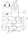
- FIG. 1 shows a schematic diagram of a direct current motor system which includes an electronic control topology in accordance with the invention.
- the system includes a battery 20 and a series wound DC traction motor, generally referred to by reference 24 which includes an armature 26 and a field winding 28 having associated motor direction contactors 30, 31 for reversing a direction of a torque of the motor 24.
- the circuit is provided with a disconnect 22 used for disconnecting the battery from the motor.
- a fuse 32 protects the circuit from extreme current conditions which can arise, for instance, if short circuit condition develops in the system.
- Other details of the circuit are constructed in accordance with well-known electrical principles which are familiar to those skilled in the art.
- the electronic control in accordance with the invention includes that portion of the diagram in FIG. 1 surrounded by the dotted line on the left hand side of the figure.
- the control includes a microprocessor 34 which receives an input signal from an accelerator potentiometer 36.
- the microprocessor 34 processes the accelerator input and outputs signals to a control logic 38.
- Those signals include an enable signal 42 and a pulse-width modulated motor current command (PWM) signal 44.
- PWM pulse-width modulated motor current command
- the signals that the microprocessor 34 outputs on enable line 42 and PWM line 44 are dependent on a number of variables in addition to the input signal from the accelerator potentiometer 36.
- Other variables which affect the microprocessor output on the enable line 42 and the PWM line 44 may include battery current, motor current, motor direction, battery voltage, control heat sink temperature, hydraulic pump status, and seat switch status if the control 33 is installed in a vehicle having an operator's seat.
- the plug-braking diode commutes armature current when the motor field is reversed for an operation known as “plug braking", commonly used to slow down an electric vehicle by reversing the polarity of the motor. It is hereinafter assumed that those skilled in the art of electronic controls are familiar with the algorithms used to generate a PWM signal for controlling the current to a DC motor.
- a control logic circuit 38 drives the gate electrodes of a plurality of motor MOSFETs 50, hereinafter referred to as "Motor FETs", and the gate electrodes of a plurality of synchronous-rectification MOSFETs 51, referred to as "SR FETs”, as noted above.
- Motor FETs motor MOSFETs 50
- SR FETs synchronous-rectification MOSFETs
- Motor FETs 50 are switched on and off by the common control line 48 in an on-off cycle of conduction to provide drive current to the motor 24 from the battery 20.
- Motor FETs 50 are switched off, the motor 24 resists the decay of current on commutation of the supply current by the Motor FETs 50.
- reverse connected "free-wheeling" diodes have been parallel connected with the motor to commute the inductive load when the Motor FETs 50 are switched off.
- SR FETs 51 which are switched on when Motor FETs 50 are switched off thus providing a path of conduction for the armature current of motor 24 as the current path through Motor FETs 50 is closed.
- the timing of the on-off cycle of Motor FETs 50 and SR FETs 51 is critical and shall be explained in more detail below in relation to FIGS. 3 and 4.
- the control in accordance with the invention also includes a plurality of capacitors 49, as is common in MOSFET controllers.
- the capacitors are preferably low equivalent-series-resistance, low inductance and high capacitance components which isolate the battery from the ripple current created by the switching cycle of the MOSFETs.
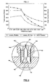
- FIG. 2 shows a graph of the theoretical loss comparisons for controllers based on a free-wheel diode control system as compared with a synchronous-rectification control system in accordance with the invention.
- the horizontal axis of the graph represents the percent duty cycle of the motor current drive signal. Duty cycle is a measure of the pulse width of the motor current drive signal. At a 100% duty cycle, the motor is connected to the battery via the Motor FETs 50 100% of the time, while at a 20% duty cycle the motor is connected to the battery 20% of the time.
- the vertical axis of the graph represents both the motor current in Amps and the controller energy losses in Watts.
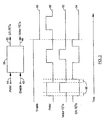
- FIG. 3 is a timing diagram illustrating the inputs and outputs of control logic circuit 38.
- the purpose of the control logic circuit 38 is to generate gate signals which turn the Motor FETS 50 on when the PWM is driven high and to turn the SR FETs 51 on when the Motor FETS 50 are off, thus preventing the Motor FETs 50 and SR FETS 51 from being simultaneously conductive.
- the control logic also receives an enable signal which permits microprocessor 34 (see FIG. 1) to turn off both the Motor FETs and the SR FETs if a fault condition is detected.
- microprocessor 34 outputs a PWM motor current command signal on PWM line 44 and an enable signal on enable line 42 to control logic circuit 38.
- the control logic circuit 38 outputs a Motor FET gate control signal on line 48 and a SR FET gate control signal on line 52.
- the microprocessor 34 preferably outputs the PWM pulse at 20,000 Hz, which is well within the operating limits of the Motor FETs 50 and the SR FETs 51.
- microprocessor 34 generates an enable signal and a PWM signal on lines 42 and 44 respectively.
- the enable signal is driven-high at all times factors monitored by the microprocessor 34 indicate that the system is in a safe operating condition.
- the enable signal 88 is driven low to ensure that both Motor FETs and SR FETs are switched off whenever a parameter monitored by the microprocessor 34 indicates a system or operator malfunction. For instance, if a vehicle is equipped with a seat switch and the operator leaves the seat of the vehicle for a predetermined length of time, the enable signal is driven low and the control logic cuts power to the drive motor 24 (see FIG.
- a PWM signal 90 is generated by the microprocessor 34 in response to an output of an accelerator potentiometer 36, as well as other variables monitored by the microprocessor and described above.
- a time delay 86 separates the periods when the Motor FETs 50 are switched on and the periods when the SR FETs 51 are switched on.
- the time delay 86 is necessary to accommodate the switching response time of the FET devices. Power FETs may take as long as 700 ns to switch fully off in response to a gate signal. Without time delay 86, a brief period would exist when the motor FETs 50 and SR FETs 51 were both conductive, resulting in large current surges. This delay is preferably a few tens of nanoseconds longer than the device switch response time of the respective FETs.
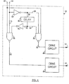
- FIG. 4 shows a schematic diagram of a preferred embodiment of the control logic circuit 38.
- the PWM line 44 and the enable line 42 transmit signals from the microprocessor 34 (see FIG. 1) to the control logic circuit 38.
- the PWM line 44 is connected to a first phase inverter 54 whose output is connected to an AND gate 74 by connection 56 and to a delay circuit 62 by connection 60.
- the delay circuit 62 may constitute any number of circuits that are capable of delaying an electrical pulse without undue distortion. Without the delay circuit 62, the drive circuits 80 and 84 for each of the Motor FETs and the SR FETs would be switched on almost simultaneously and would be mutually conductive for a brief period of time that would be adequate to short circuit the control system and cause damage to the electronic components of the controller.
- Delay circuit 62 must therefore delay a pulse by at least the device switch time of the FETs used in the control. Typically, a delay of about 750 nanoseconds is appropriate.
- the output of delay circuit 62 is connected by connection 64 to AND gate 74 and by connection 66 to a second phase inverter 70 which inverts the phase of an electrical pulse to its original condition.
- the output of phase inverter 70 is connected to a second AND gate 58 which also receives pulsed signals directly from PWM line 44 via connection 76.
- the output of AND gate 58 is directed to a drive circuit 84 for the Motor FETs 50 by a connection 48.
- the output of AND gate 74 is connected by a connection 78 to a drive circuit 80 for the SR FETs 51 (see FIG. 1).
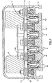
- FIG. 5 shows a cross-sectional view of a preferred embodiment of a novel physical structure for a motor control in accordance with the invention.
- the physical structure for a motor controller in accordance with the invention provides an alternate method of ensuring heat conducting contact between the electronic switching components and the heat sink structure of a controller.
- the physical structure of a preferred embodiment of a motor controller includes a heat sink base 96.
- the base 96 has a top surface which includes a plurality of spaced apart channels 98 for receiving electronic switching components such as Motor FETs 50, SR FETs 51, plug brake diodes 46, and ancillary circuits. These electronic components are attached by their respective legs to a current control board 100 that is supported on the top surface of the heat sink base 96.
- a plurality of power bar conductors 102 rest atop current control board 100. There are preferably five power bars 102 provided. Two power bars are connected to the opposite poles of the battery 20 (see FIG. 1).
- One power bar 102 is connected to the motor field 28, one power bar 102 is connected to motor field/armature conjunction and one power bar 102 is connected to the motor armature 26.
- a capacitor board 104 rests atop the power bars 102 and supports capacitors 49. Preferably, low equivalent-series-resistance, low inductance high capacitance capacitors are connected in two rows of four capacitors each along opposite edges of the capacitor board 104.
- a microprocessor board 106 is supported on a top surface of capacitor board 104 between the opposite rows of capacitors 49. Microprocessor board 106 supports the microprocessor 34 and related circuitry.
- the electronic switching components are first connected to the circuit control board 100 by inserting their respective legs into preformed holes in the circuit board 100 but the legs are not soldered to the printed circuit at this stage of the process.
- Electronic components of the controller are electrically insulated from the heat sink base 96. It is therefore necessary to position electrically insulating/heat conducting sheets 108 between the components and the heat sink base 96.
- the insulating sheets 108 are generally made of a specifically formulated plastic polymer which readily conducts heat but not electricity.
- the insulating sheets 108 are well-known in the art and widely available. Because insulating sheet 108 is pliable, the electronic components must be inserted into channels 98 without making intimate contact with the sheets 108.
- each retainer member 110 is preferably a structure with a dogleg-shaped cross-section made of a spring steel, or the like, each retainer member 110 is provided with registration tabs 101 which mates with alignment holes in the current control board 100.
- the insertion and positioning of retainer members 110 will be explained in more detail below in relation to FIG. 6. As is apparent, retainer members 110 exert a constant pressure to urge electrical components into contact with insulating sheets 108 for a direct heat conduction to the heat sink 96.
- the various components of the controller are locked in an assembled condition by screw fasteners or the like which pass through preformed holes in the circuit boards and engage appropriately positioned nuts 112 that slide in inverted T-shaped slots 114 which are machined between the channels 98 in the top surface of the heat sink base 96.
- FIG. 6 shows a detailed cross-sectional view of the electrical component fastening system in accordance with the invention.
- the channels 98 for receiving electrical components attached to the current control board 100 are preferably machined with two spaced apart parallel ridges 116 on a bottom surface of the channel.
- the retainer members 110 are slid into the channel with their bottom ends between the ridges 116.
- an elongated key having a triangular cross-section and a tapered front end (not illustrated) is inserted between the retainer members and guided by the channel formed by the ridges 116 to force the bottom edges of each retainer member over a corresponding ridge 116.
- the invention provides an electric motor control topology which has broad application in the construction of light-weight efficient electronic controls for electrically driven, battery operated trucks and the like.
- a superior energy efficient control is provided which is not prone to enter a condition of thermal cutback even under conditions of sustained lugging or prolonged acceleration.
- the invention also provides an electronic control for direct current traction motors which reduces energy consumption, especially at low operational speeds under which most truck motors operate a majority of the time.
- the invention also provides electronic controls for direct current traction motors which are more economic to construct than prior art controls.
- the economy of construction is achieved by using inexpensive MOSFET components for switching pulse width modulated electric current to the motor and commuting armature current when the pulse width modulated drive current is off.
- the controller in accordance with the invention provides the further advantage of a controller having a commutation frequency that operates above the upper frequency threshold of hearing for most human beings.
- the controller therefore provides equipment which is safer to operate because operators are not fatigued by audible frequency noise generated by the commutation of a controller for the equipment.
- the invention also provides a light-weight MOSFET switched DC motor controller which is suitable for Class 1 and Class 2 electrically powered trucks thus providing an inexpensive energy efficient electronic controller for such vehicles.
Abstract
Description
- The present invention relates to direct current motor control systems used in controlling the rotational speed of traction motors for battery-powered vehicles and, in particular, to a novel DC motor control topology and structure.
- The control systems which currently dominate the battery-powered direct current motor market fall into two principal categories, control systems which use silicon controlled rectifiers and those which use metal-oxide-semiconductor field effect transistors for switching DC current to control motor speed.
- Silicon controlled rectifiers (SCRs) are commonly employed in heavy equipment control devices for providing a variable mark-space ratio power regulator responsive to a motor current command signal. SCR controllers have been widely accepted and are proven to be reliable in most operating conditions. SCR controllers do have disadvantages, however. SCR controllers are physically bulky and massive. They also are known to dissipate substantial amounts of energy and they are not well suited for automated assembly techniques. In addition, although SCR devices are readily switched on extra commutation circuity is required to switch them off. A further problem with SCR controllers is that the commutation frequency of those controllers is in the audible range, commonly at 2000 Hz or less. During operation, SCR controllers therefore tend to emit an audible hum and a poorly designed SCR controller can emit noise which humans find irritating and fatiguing.
- More recently, metal-oxide-semiconductor field effect transistor (MOSFET) controllers have been invented. Such controllers are disclosed in U.S. Patent 4,626,750 which issued December 2, 1986 to Curtis Instruments.
- In these controllers silicon controlled rectifiers are replaced with a plurality of MOSFETS for switching battery current in an on-off pulse to vary the current to the drive motor, thereby varying the motor torque and consequently the motor's rotational speed. MOSFETs are advantageous because they have a high input impedance, low energy dissipation and are readily switched from a conductive to a nonconductive state without additional circuitry. MOSFETs are also advantageous because they are small devices that are well suited for use with automated assembly techniques. They are further advantageous because the per unit cost of the device is rapidly decreasing as a result of utilization in a wide range of consumer, industrial and automotive applications. MOSFETs are also switchable at frequencies which are at the limit of, or beyond the audible range for humans so that MOSFET controllers reduce or eliminate controller-generated audible noise.
- These two types of DC motor controllers, collectively known as pulse-width modulated (PWM) motor controllers, include free-wheeling diodes for commuting armature current generated by a motor during periods of operation when the battery current is switched off. Without free-wheeling diodes, the voltage transient generated by the armature when the switching device opens would destroy the control. Although free-wheeling diodes are effective for commuting those currents, they have the disadvantage of contributing to significant power losses through waste heat generation. For example, a forklift accelerating up a grade may require 500 A to the motor armature at a 20 percent PWM duty cycle. Under such conditions, free-wheeling diodes generate some 480 Watts, assuming a forward voltage drop of 1.2 V at 500 A which is typical of free-wheeling diodes. Prior art MOSFET controls go into "thermal cutback" under heavy lugging and prolonged acceleration as a result of this heat generation by the free-wheeling diodes. Consequently, MOSFET controllers have not been used extensively in the
Class 1 and Class 2 truck markets. MOSFET controllers have only seen reasonable acceptance in the smaller Class 3 walk behind truck market and small electric vehicle markets, such as electric golf carts and light baggage carriers. - United States Patent 4,906,906 to Lautzenhiser et al. discloses an electrically powered wheelchair having automatic limiting of the rate of change in power supplied to left and right propulsion motors, whether electrically or hydraulically propelled. The electric propulsion motors are permanent magnet motors. The electric propulsion motors are powered by a pulse-width-modulated driving voltage that is chopped by a single MOSFET device. During intervals that the drive power pulse is switched off, the motor armature is electrically loaded to provide dynamic braking. The electrical load is supplied through a second single MOSFET device. Mutual conduction of the first and second MOSFETS is prevented by turning on the MOSFET devices more slowly than they are turned off. The slow turn on of the devices is effected using a time-delay resistor and a parasitic capacitor. It has been established that switching losses in MOSFET devices are four times greater than conduction losses. This controller is therefore limited to motors having a low power consumption requirement. The control would not function satisfactorily under high current demands because the excess heat losses due to slow switching would tend to damage the solid state components of the controller.
- It is an object of the invention to provide an electronic controller for a direct current traction motor which permits sustained creeping and lugging of a vehicle driven by the motor without entering a condition of thermal cutback due to heat build-up in the physical structure of the controller.
- It is a further object of the invention to provide an electronic controller for direct current traction motors which reduces energy consumption, especially during vehicle lugging and creeping conditions.
- It is yet a further object of the invention to provide an electronic controller for direct current traction motors which is more economic to construct than prior art controllers.
- It is another object of the invention to provide an electronic controller which operates at a commutation frequency that is above the upper frequency threshold of hearing for human beings.
- It is yet a further object of the invention to provide a MOSFET switched DC motor controller which is suitable for use in
Class 1 and Class 2 electrically powered trucks. - A DC motor control in accordance with the invention uses a technique hereinafter referred to as "synchronous-rectification" in which the free-wheeling diodes in prior art controllers are replaced with MOSFET devices. The synchronous-rectification MOSFETs, hereinafter referred to as "SR FETs" are switched on during intervals that free-wheeling diodes would be conducting. Since MOSFETs have a much lower forward voltage drop than free-wheeling diodes, the resulting control is significantly more efficient. In the example described above, free-wheeling diodes generate some 400 Watts while SR FETs under equivalent conditions generate only about 120 Watts.
Consequently, synchronous-rectification significantly reduces controller heating during heavy lugging and prolonged acceleration. synchronous-rectification controls are therefore capable of sustained high amperage throughputs and are suitable for use inClass 1 and 2 trucks as well as Class 3 trucks. - The invention thus provides an electronic control as set forth in
claim 1. Preferred embodiments may be gathered from the dependent claims. - A physical structure for a direct current traction motor controller of the invention is provided, which includes a heat sink structure having a top surface; the top surface of the heat sink structure including at least two spaced-apart channels for receiving a first and second plurality of electronic components affixed to a circuit board positioned on the top surface; and, at least two elongated retainers respectively insertable in the channels while the electronic components are received therein, the retainers being movable after insertion in the channels to a disposition wherein they urge the respective first and second plurality of electronic components to a heat exchanging contact with a sidewall of the respective channels. This physical structure permits a high density packing of electronic components.
- The invention thus provides a novel energy-conserving control topology, and a novel physical structure for a DC motor controller which is more economically assembled and permits a higher packing density of components than prior art controls for motors of the same type.
- Synchronous-rectification type controls are suitable for use with series wound motors as well as separately excited motors. Although the description of the preferred embodiments which follows relates to series wound motors, the invention is in no way limited to series wound motors in its utility.
- The invention will now be described by way of example only and with reference to the following drawings, wherein:
- FIG. 1 is a schematic diagram of the topology of an electronic control for a direct current traction motor in accordance with the invention;
- FIG. 2 is a graph of the theoretical loss comparisons of a prior art MOSFET control which uses free-wheel diodes to commute motor current compared to a synchronous-rectification type control in accordance with the invention;
- FIG. 3 is a schematic diagram of the control logic circuit illustrating the relationship between the enable and pulse-width modulated signals input to the control logic circuit and the motor FET and SR FET output signals generated by the control logic circuit;
- FIG. 4 is a simplified schematic circuit diagram of a preferred embodiment of the control logic circuit in accordance with the invention;
- FIG. 5 is a cross-sectional view of a preferred physical structure for a controller in accordance with the invention; and
- FIG. 6, which is on sheet two of the drawings, is a detailed view of a locking system for securing circuit components to sidewalls of the channels in a heat sink of the structure shown in FIG. 5.
- FIG. 1 shows a schematic diagram of a direct current motor system which includes an electronic control topology in accordance with the invention. The system includes a
battery 20 and a series wound DC traction motor, generally referred to byreference 24 which includes an armature 26 and a field winding 28 having associated motor direction contactors 30, 31 for reversing a direction of a torque of themotor 24. - The circuit is provided with a disconnect 22 used for disconnecting the battery from the motor. A
fuse 32 protects the circuit from extreme current conditions which can arise, for instance, if short circuit condition develops in the system. Other details of the circuit are constructed in accordance with well-known electrical principles which are familiar to those skilled in the art. - The electronic control in accordance with the invention, generally referred to by
reference 33, includes that portion of the diagram in FIG. 1 surrounded by the dotted line on the left hand side of the figure. The control includes amicroprocessor 34 which receives an input signal from anaccelerator potentiometer 36. Themicroprocessor 34 processes the accelerator input and outputs signals to acontrol logic 38. Those signals include an enablesignal 42 and a pulse-width modulated motor current command (PWM)signal 44. As will be understood by those skilled in the art, the signals that themicroprocessor 34 outputs on enableline 42 andPWM line 44 are dependent on a number of variables in addition to the input signal from theaccelerator potentiometer 36. Other variables which affect the microprocessor output on theenable line 42 and thePWM line 44 may include battery current, motor current, motor direction, battery voltage, control heat sink temperature, hydraulic pump status, and seat switch status if thecontrol 33 is installed in a vehicle having an operator's seat. There is also a "plug braking" sensing circuit which monitors the direction of flow of current through aplug brake diode 46 that is connected in parallel with the armature ofmotor 24. The plug-braking diode commutes armature current when the motor field is reversed for an operation known as "plug braking", commonly used to slow down an electric vehicle by reversing the polarity of the motor. It is hereinafter assumed that those skilled in the art of electronic controls are familiar with the algorithms used to generate a PWM signal for controlling the current to a DC motor. - A
control logic circuit 38 drives the gate electrodes of a plurality ofmotor MOSFETs 50, hereinafter referred to as "Motor FETs", and the gate electrodes of a plurality of synchronous-rectification MOSFETs 51, referred to as "SR FETs", as noted above. - The function of
Motor FETs 50 is well understood in the art.Motor FETs 50 are switched on and off by thecommon control line 48 in an on-off cycle of conduction to provide drive current to themotor 24 from thebattery 20. WhenMotor FETs 50 are switched off, themotor 24 resists the decay of current on commutation of the supply current by theMotor FETs 50. In prior art controllers, reverse connected "free-wheeling" diodes have been parallel connected with the motor to commute the inductive load when theMotor FETs 50 are switched off. In accordance with the invention, those free-wheeling diodes are replaced bySR FETs 51 which are switched on whenMotor FETs 50 are switched off thus providing a path of conduction for the armature current ofmotor 24 as the current path throughMotor FETs 50 is closed. The timing of the on-off cycle ofMotor FETs 50 andSR FETs 51 is critical and shall be explained in more detail below in relation to FIGS. 3 and 4. - The control in accordance with the invention also includes a plurality of
capacitors 49, as is common in MOSFET controllers. The capacitors are preferably low equivalent-series-resistance, low inductance and high capacitance components which isolate the battery from the ripple current created by the switching cycle of the MOSFETs. - FIG. 2 shows a graph of the theoretical loss comparisons for controllers based on a free-wheel diode control system as compared with a synchronous-rectification control system in accordance with the invention.
- The horizontal axis of the graph represents the percent duty cycle of the motor current drive signal. Duty cycle is a measure of the pulse width of the motor current drive signal. At a 100% duty cycle, the motor is connected to the battery via the
Motor FETs 50 100% of the time, while at a 20% duty cycle the motor is connected to thebattery 20% of the time. The vertical axis of the graph represents both the motor current in Amps and the controller energy losses in Watts. - As is apparent from the graph, theoretical losses in free-wheel diode control systems are dramatically greater than theoretical losses in synchronous-rectification control systems. This is especially true when duty cycles are below 50 percent and motor currents are 400 A or more. These conditions of motor operation are commonly referred to as "lugging" conditions. It is well-known that during lugging of DC motors, free-wheel diode type control systems tend to enter thermal cutback wherein the duty cycle is reduced in order to permit waste heat built up in the control heat sink to dissipate. As is apparent from the graph, cutback of the duty cycle can cause more rapid heating, further exacerbating the problem. The theoretical losses in waste heat energy are cut by almost 50% at a 10% duty cycle, and more than 30% at a 50% duty cycle. Synchronous-rectification type controls therefore significantly reduce heating in the physical structure of a controller during heavy lugging and prolonged acceleration by improving the energy efficiency of the control system.
- FIG. 3 is a timing diagram illustrating the inputs and outputs of
control logic circuit 38. The purpose of thecontrol logic circuit 38 is to generate gate signals which turn theMotor FETS 50 on when the PWM is driven high and to turn theSR FETs 51 on when theMotor FETS 50 are off, thus preventing theMotor FETs 50 andSR FETS 51 from being simultaneously conductive. The control logic also receives an enable signal which permits microprocessor 34 (see FIG. 1) to turn off both the Motor FETs and the SR FETs if a fault condition is detected. As seen at the top of FIG. 3,microprocessor 34 outputs a PWM motor current command signal onPWM line 44 and an enable signal on enableline 42 to controllogic circuit 38. Thecontrol logic circuit 38 outputs a Motor FET gate control signal online 48 and a SR FET gate control signal online 52. In order to provide an electronic DC motor control which does not emit noise in the range audible to humans, themicroprocessor 34 preferably outputs the PWM pulse at 20,000 Hz, which is well within the operating limits of theMotor FETs 50 and theSR FETs 51. - At the bottom of FIG. 3 are shown the input and output signals of
control logic 38 in relation to a time-line. As explained above,microprocessor 34 generates an enable signal and a PWM signal onlines microprocessor 34 indicate that the system is in a safe operating condition. The enablesignal 88 is driven low to ensure that both Motor FETs and SR FETs are switched off whenever a parameter monitored by themicroprocessor 34 indicates a system or operator malfunction. For instance, if a vehicle is equipped with a seat switch and the operator leaves the seat of the vehicle for a predetermined length of time, the enable signal is driven low and the control logic cuts power to the drive motor 24 (see FIG. 1) by switching off both theMotor FETs 50 and theSR FETs 51. APWM signal 90 is generated by themicroprocessor 34 in response to an output of anaccelerator potentiometer 36, as well as other variables monitored by the microprocessor and described above. As is apparent from FIG. 3, a time delay 86 separates the periods when theMotor FETs 50 are switched on and the periods when theSR FETs 51 are switched on. The time delay 86 is necessary to accommodate the switching response time of the FET devices. Power FETs may take as long as 700 ns to switch fully off in response to a gate signal. Without time delay 86, a brief period would exist when themotor FETs 50 andSR FETs 51 were both conductive, resulting in large current surges. This delay is preferably a few tens of nanoseconds longer than the device switch response time of the respective FETs. - As will be apparent to those skilled in the art, many techniques exist for generating the signals illustrated in FIG. 3.
- FIG. 4 shows a schematic diagram of a preferred embodiment of the
control logic circuit 38. ThePWM line 44 and the enableline 42 transmit signals from the microprocessor 34 (see FIG. 1) to thecontrol logic circuit 38. ThePWM line 44 is connected to afirst phase inverter 54 whose output is connected to an ANDgate 74 byconnection 56 and to adelay circuit 62 by connection 60. Thedelay circuit 62 may constitute any number of circuits that are capable of delaying an electrical pulse without undue distortion. Without thedelay circuit 62, thedrive circuits Delay circuit 62 must therefore delay a pulse by at least the device switch time of the FETs used in the control. Typically, a delay of about 750 nanoseconds is appropriate. The output ofdelay circuit 62 is connected byconnection 64 to ANDgate 74 and byconnection 66 to asecond phase inverter 70 which inverts the phase of an electrical pulse to its original condition. The output ofphase inverter 70 is connected to a second AND gate 58 which also receives pulsed signals directly fromPWM line 44 viaconnection 76. The output of AND gate 58 is directed to adrive circuit 84 for theMotor FETs 50 by aconnection 48. The output of ANDgate 74 is connected by aconnection 78 to adrive circuit 80 for the SR FETs 51 (see FIG. 1). - FIG. 5 shows a cross-sectional view of a preferred embodiment of a novel physical structure for a motor control in accordance with the invention. Because DC motor controls switch large amounts of current, a path for waste heat dissipation from electronic switching components such as MOSFETS and diodes must be provided. Although the synchronous-rectification system in accordance with the invention generates less heat than prior art DC motor control systems, a physical structure for a controller which accommodates and facilitates the ready dissipation of waste heat is essential for efficient controller operation and extended service life. In order to ensure efficient heat dissipation, the heat generating electronic components must be maintained in close physical contact with an efficient heat sink structure. Such contact has been assured in prior art controls by the use of screw fasteners or the like. Although screw fasteners are reliable and effective, they are labour-intensive to install and therefore contribute to the cost of manufacturing a control. The physical structure for a motor controller in accordance with the invention provides an alternate method of ensuring heat conducting contact between the electronic switching components and the heat sink structure of a controller.
- As shown in FIG. 5, the physical structure of a preferred embodiment of a motor controller includes a
heat sink base 96. Thebase 96 has a top surface which includes a plurality of spaced apartchannels 98 for receiving electronic switching components such asMotor FETs 50,SR FETs 51, plugbrake diodes 46, and ancillary circuits. These electronic components are attached by their respective legs to acurrent control board 100 that is supported on the top surface of theheat sink base 96. A plurality ofpower bar conductors 102 rest atopcurrent control board 100. There are preferably fivepower bars 102 provided. Two power bars are connected to the opposite poles of the battery 20 (see FIG. 1). Onepower bar 102 is connected to themotor field 28, onepower bar 102 is connected to motor field/armature conjunction and onepower bar 102 is connected to the motor armature 26. Acapacitor board 104 rests atop thepower bars 102 and supportscapacitors 49. Preferably, low equivalent-series-resistance, low inductance high capacitance capacitors are connected in two rows of four capacitors each along opposite edges of thecapacitor board 104. Amicroprocessor board 106 is supported on a top surface ofcapacitor board 104 between the opposite rows ofcapacitors 49.Microprocessor board 106 supports themicroprocessor 34 and related circuitry. - In order to assemble a DC motor controller efficiently, a quick and simple method of ensuring a heat conductive contact between the electronic components of the controller and the controller heat sink is required. Electronic components such as FETs and diodes are commonly available in a component package which meets JEDEC (Joint Electron Device Engineering Council) standards. Commonly available packages are the TO220 package and the T0247 package. Either of these component packages is suitable for use in a physical structure for a controller in accordance with the invention.
- In assembling a physical structure of a controller in accordance with the invention, the electronic switching components are first connected to the
circuit control board 100 by inserting their respective legs into preformed holes in thecircuit board 100 but the legs are not soldered to the printed circuit at this stage of the process. Electronic components of the controller are electrically insulated from theheat sink base 96. It is therefore necessary to position electrically insulating/heat conducting sheets 108 between the components and theheat sink base 96. The insulatingsheets 108 are generally made of a specifically formulated plastic polymer which readily conducts heat but not electricity. The insulatingsheets 108 are well-known in the art and widely available. Because insulatingsheet 108 is pliable, the electronic components must be inserted intochannels 98 without making intimate contact with thesheets 108. This is the principal reason for not soldering the legs of the components to thecurrent control board 100 as it permits the components to be tilted together for insertion intorespective channels 98. After the components are inserted in the channels, a pair ofretainer members 110 are slid between the components. Each retainer member is preferably a structure with a dogleg-shaped cross-section made of a spring steel, or the like, eachretainer member 110 is provided withregistration tabs 101 which mates with alignment holes in thecurrent control board 100. The insertion and positioning ofretainer members 110 will be explained in more detail below in relation to FIG. 6. As is apparent,retainer members 110 exert a constant pressure to urge electrical components into contact with insulatingsheets 108 for a direct heat conduction to theheat sink 96. Thus, an efficient transfer of waste heat is accommodated without the use of screw fasteners or other time consuming fastening techniques. In practice, it is important thatmotor FETs 50 andSR FETs 51 be installed inadjacent channels 98. The juxtaposition of the FETs is necessary to reduce stray inductance which could generate voltage that might destroy the FETs. - The various components of the controller are locked in an assembled condition by screw fasteners or the like which pass through preformed holes in the circuit boards and engage appropriately positioned
nuts 112 that slide in inverted T-shapedslots 114 which are machined between thechannels 98 in the top surface of theheat sink base 96. - FIG. 6 shows a detailed cross-sectional view of the electrical component fastening system in accordance with the invention. The
channels 98 for receiving electrical components attached to thecurrent control board 100 are preferably machined with two spaced apartparallel ridges 116 on a bottom surface of the channel. Theretainer members 110 are slid into the channel with their bottom ends between theridges 116. Afterretainer members 110 are inserted inchannel 98 an elongated key having a triangular cross-section and a tapered front end (not illustrated) is inserted between the retainer members and guided by the channel formed by theridges 116 to force the bottom edges of each retainer member over acorresponding ridge 116. Theretainer member 110 shown on the left of FIG. 6 has been forced overridge 116 using the key. Theopposite retainer member 110 on the right is shown in a relaxed condition. Using this method, electrical components are quickly and easily locked in a heat exchanging relationship with the slides ofchannels 98 and the time consuming steps of drilling and tapping holes to receive screw fasteners for securing the components to theheat sink base 96 are completely eliminated. This technique also permits significantly higher component packing density because space for accommodating drilling, tapping and/or screw fastener driving equipment need not be provided. After the electronic components are locked in place against the sides of thechannels 98, the legs of each component are soldered to the printed circuit and the remainder of the controller is assembled. This method permits the assembly of a DC motor controller in less time and at less expense than prior art methods. - The invention provides an electric motor control topology which has broad application in the construction of light-weight efficient electronic controls for electrically driven, battery operated trucks and the like. A superior energy efficient control is provided which is not prone to enter a condition of thermal cutback even under conditions of sustained lugging or prolonged acceleration. The invention also provides an electronic control for direct current traction motors which reduces energy consumption, especially at low operational speeds under which most truck motors operate a majority of the time.
- The invention also provides electronic controls for direct current traction motors which are more economic to construct than prior art controls. The economy of construction is achieved by using inexpensive MOSFET components for switching pulse width modulated electric current to the motor and commuting armature current when the pulse width modulated drive current is off.
- The controller in accordance with the invention provides the further advantage of a controller having a commutation frequency that operates above the upper frequency threshold of hearing for most human beings. The controller therefore provides equipment which is safer to operate because operators are not fatigued by audible frequency noise generated by the commutation of a controller for the equipment.
- The invention also provides a light-weight MOSFET switched DC motor controller which is suitable for
Class 1 and Class 2 electrically powered trucks thus providing an inexpensive energy efficient electronic controller for such vehicles. - Those skilled in the art will recognize that the invention has wide industrial applicability and not only enhances the capabilities of electric powered vehicles but also opens opportunity for new electric powered applications.
- The specific embodiments hereinbefore described are intended to be exemplary only, the scope of the invention being limited solely by the scope of the appended claims.
Claims (13)
- An electronic control (33) for a direct current traction motor (24) having a first power field effect transistor (50) arranged for connection in series with the motor (24), a field gate electrode of the first field effect transistor (50) being connected to a first control line (48) for controlling an on-off cycle of conduction through the first field effect transistor (SO) to provide a pulsed drive current to the motor (24) from a direct current source (20), and a second power field effect transistor (51) arranged for connection in parallel with the motor (24), a field gate electrode of the second field effect transistor (51) being connected to a second control line (52) for controlling conduction through the second field effect transistor (51) for commuting a motor current when the first field effect transistor (50) is switched off,
CHARACTERIZED IN THATthe electronic control (33) comprises a first plurality of parallel-connected power field effect transistors (50) arranged for connection in series with the motor (24), a gate electrode of each first field effect transistor being connected to said first control line (48);a second plurality of parallel-connected power field effect transistors (51) arranged for connection in parallel with the motor (24), a field gate electrode of each second field effect transistor (51) being connected to said second control line (52) for controlling a synchronous-rectification on-off cycle of conduction through the second field effect transistors (51); anda control logic circuit (38) for switching on the first and second plurality of field effect transistors (50, 51), the control logic circuit outputting pulses on the first and second common control lines (48, 52), the pulses being separated by a time delay which exceeds the device switch time of the field effect transistors (50, 51), and whereina microprocessor (34) outputs two separate signals to the control logic circuit (38), a pulse width modulated on-off motor current regulation command signal (44) and an enable signal (42) to ensure that both the first and second plurality of power field effect transistors (50, 51) are switched off if the enable signal (42) indicates that a fault condition is detected. - The electronic control as claimed in claim 1, characterized in that the control logic circuit (38) includes a first inverter (54), a pulse delay circuit (62), a second inverter (70), first and second electrical AND gates (74, 58) and first and second drive circuits (80, 84) in electrical connection with the first and second discrete output lines (42, 44).
- The electronic control as claimed in claims 1, or 2, characterized in that the pulse-width modulated on/off motor current regulation signal (44) is cycled at a frequency of at least 15,000 Hz so that the control (33) does not emit noise in an audible range for humans.
- The electronic control as claimed in any preceding claim, characterized in that the control (33) further includes at least one plug braking diode (46) connected in parallel with an armature (26) of the motor (24) to commute armature current when a polarity of a field (28) of the motor (24) is reversed.
- The electronic control as claimed in any preceding claim, characterized in that the control (33) further includes at least one low resistance, low inductance capacitor (49) connected in parallel with a battery (20) for providing the direct current supply, said capacitor (49) having a capacitance adequate to even a load on the battery (20) to an extent that the load is substantially constant.
- The electronic control (33) as claimed in claim 1 characterized in that the physical structure of the electronic control (33) comprises:a heat sink structure (96) having a top surface, the top surface including at least two spaced-apart channels (98) for receiving a first and second plurality of electronic components (46, 50, 51) affixed to a circuit board (100) positioned on the top surface; anda retainer member (110) insertable in each channel (98) while the electronic components (46, 50, 51) are received therein, said retainer member (110) being movable after insertion in the channel (98) to a disposition that urges the electronic components (46, 50, 51) into a heat exchanging contact with a sidewall of a respective channel (110).
- The electronic control as claimed in claim 6 characterized in that two rows of a plurality of electronic components (46, 50, 51) are received in each channel (98) and two retainer members (110) are inserted in each channel (98) to urge the respective rows of components against opposite sidewalls of each channel (98), thereby providing a high packing density of electronic components (46, 50, 51) in the electronic control (33).
- The electronic control as claimed in claim 6 characterized in that a first plurality of parallel connected power field effect transistors (50) arranged for connection in series with the motor (24) to provide drive current to the motor from a direct current source (20) is installed in a first channel (98) in the heat sink structure (96), and a second plurality of parallel connected power field effect transistors (51), arranged for connection in parallel with the motor (24) to commute a motor current when the first field effect transistors (50) are switched off, is installed in a second channel (98) in the heat sink structure (96); said first and second channels (98) being adjacent so that the generation of stray inductance by the first and second plurality of field effect transistors (50, 51) is minimized.
- The electronic control as claimed in claim 6, characterized in that the retainer member (110) is a resilient member that is inserted into the channels (98) in a relaxed state and moved to a tensioned disposition wherein the retainer member (110) exerts a constant pressure against the respective electronic components (46, 50, 51) in a channel to urge the components against a sidewall of the channel (98) in order to facilitate a conduction of waste heat from the electronic components (46, 50, 51) to the heat sink structure (96).
- The electronic control as claimed in claim 9, characterized in that the retainer members (110) are elongated spring steel leaves.
- The electronic control as claimed in claim 10, characterized in that each channel (98) includes at least one ridge (116) on a bottom wall thereof and a side of the ridge (116) retains an edge of the retainer member (110) when the retainer member (110) is moved to the tensioned disposition.
- The electronic control as claimed in claim 11, characterized in that the bottom wall of each channel (98) includes two parallel spaced apart ridges (116) and a side of the ridge (116) adjacent a sidewall of the channel (98), receives a longitudinal edge of the retainer member (110) when the retainer member (110) is moved to the tensioned disposition.
- The electronic control as claimed in claim 6, characterized in that the control (33) further includes a plurality of spaced apart power bars (102) positioned on a top surface of the circuit board (100), a capacitor board (104) positioned above the power bars and a microprocessor board (106) positioned above the capacitor board.
Applications Claiming Priority (3)
| Application Number | Priority Date | Filing Date | Title |
|---|---|---|---|
| US07/859,226 US5331258A (en) | 1992-03-30 | 1992-03-30 | Synchronous-rectification type control for direct current motors and method of making |
| US859226 | 1992-03-30 | ||
| PCT/CA1993/000131 WO1993020611A2 (en) | 1992-03-30 | 1993-03-30 | Synchronous-rectification type control for direct current motors and method of making |
Publications (2)
| Publication Number | Publication Date |
|---|---|
| EP0634064A1 EP0634064A1 (en) | 1995-01-18 |
| EP0634064B1 true EP0634064B1 (en) | 1997-09-17 |
Family
ID=25330389
Family Applications (1)
| Application Number | Title | Priority Date | Filing Date |
|---|---|---|---|
| EP93907706A Expired - Lifetime EP0634064B1 (en) | 1992-03-30 | 1993-03-30 | Synchronous-rectification type control for direct current motors |
Country Status (12)
| Country | Link |
|---|---|
| US (1) | US5331258A (en) |
| EP (1) | EP0634064B1 (en) |
| KR (1) | KR100275361B1 (en) |
| AT (1) | ATE158451T1 (en) |
| AU (1) | AU668552B2 (en) |
| CA (1) | CA2133469C (en) |
| DE (1) | DE69314019T2 (en) |
| DK (1) | DK0634064T3 (en) |
| ES (1) | ES2107013T3 (en) |
| GR (1) | GR3025685T3 (en) |
| NZ (1) | NZ251285A (en) |
| WO (1) | WO1993020611A2 (en) |
Families Citing this family (28)
| Publication number | Priority date | Publication date | Assignee | Title |
|---|---|---|---|---|
| FR2720876B1 (en) * | 1994-06-02 | 1996-07-12 | Sagem | Electric vehicle engine control and command box. |
| JPH0865809A (en) * | 1994-08-25 | 1996-03-08 | Yamaha Motor Co Ltd | Motor controller for motor driven vehicle |
| DE19534174A1 (en) * | 1995-09-14 | 1997-03-20 | Linde Ag | Electric vehicle electric motor power battery charging method |
| AU7455196A (en) * | 1995-10-17 | 1997-05-07 | Fasco Industries, Inc. | A brushless dc motor assembly |
| US5896487A (en) * | 1996-03-05 | 1999-04-20 | Masten; Billy Reese | Opto-electrically controlled direct current motor speed control circuit |
| DE19617947C1 (en) * | 1996-05-04 | 1997-07-03 | Braun Ag | Power supply circuit for motor minimising mains network reaction |
| WO1998001941A1 (en) * | 1996-07-09 | 1998-01-15 | Solaria Research Enterprise, Ltd. | Control system for separately excited dc motor |
| US6000486A (en) * | 1997-04-18 | 1999-12-14 | Medicart, L.L.C. | Apparatus for providing self-propelled motion to medication carts |
| US5886487A (en) * | 1997-04-29 | 1999-03-23 | Unitrode Corporation | DC motor driver having output FETS that conduct to rectify output overvoltage and undervoltage transients |
| US6021251A (en) * | 1997-07-08 | 2000-02-01 | Crown Equipment Corporation | Compensated field current control for a separately excited DC motor |
| US6031965A (en) * | 1997-07-08 | 2000-02-29 | Solaria Research Enterprise, Ltd. | Separately excited DC motor with boost and de-boost control |
| US6226582B1 (en) | 1997-07-21 | 2001-05-01 | Sre Controls, Inc. | Integrated control for electric lift trucks |
| DE19826458A1 (en) | 1998-06-13 | 1999-12-16 | Papst Motoren Gmbh & Co Kg | Arrangement with an electric motor |
| DE19836882A1 (en) * | 1998-08-14 | 2000-02-17 | Papst Motoren Gmbh & Co Kg | Electric motor has characteristic field stored as digital values for associating parameter and motor speed values, and microcontroller or microprocessor |
| FR2782858B1 (en) * | 1998-08-28 | 2000-11-17 | Alstom Technology | IMPROVED DEVICE FOR SUPPLYING ELECTRIC CURRENT TO DRIVE MOTORS OF URBAN OR SUBURBAN VEHICLES |
| US6255789B1 (en) * | 1999-02-04 | 2001-07-03 | Matsushita Electric Industrial Co., Ltd. | Motor |
| US6652249B2 (en) * | 1999-12-13 | 2003-11-25 | Parker-Hannifin Corporation | Brushless DC wet motor fuel pump with integral controller |
| US6538405B1 (en) * | 2000-04-28 | 2003-03-25 | The Cherry Corporation | Accessory control system |
| US7656096B2 (en) * | 2003-04-30 | 2010-02-02 | International Rectifier Corporation | Hybrid ballast control circuit in a simplified package |
| US20050284448A1 (en) * | 2004-06-23 | 2005-12-29 | Forgue John R | Fuel pump system |
| JP4475403B2 (en) * | 2004-09-07 | 2010-06-09 | 三菱電機株式会社 | Electric power steering control device |
| EP1943059B1 (en) * | 2005-11-04 | 2014-03-12 | Robert Bosch Gmbh | Articulating drill with optical speed control and method of operation |
| US8604709B2 (en) | 2007-07-31 | 2013-12-10 | Lsi Industries, Inc. | Methods and systems for controlling electrical power to DC loads |
| US8903577B2 (en) | 2009-10-30 | 2014-12-02 | Lsi Industries, Inc. | Traction system for electrically powered vehicles |
| US7598683B1 (en) | 2007-07-31 | 2009-10-06 | Lsi Industries, Inc. | Control of light intensity using pulses of a fixed duration and frequency |
| US9325250B2 (en) * | 2009-01-13 | 2016-04-26 | Linear Technology Corporation | Method and system for polarity independent step-up converter capable of operating under ultra-low input voltage condition |
| US8788223B2 (en) * | 2010-10-29 | 2014-07-22 | GM Global Technology Operations LLC | Comprehensive method of electrical fluid heating system fault detection and handling |
| US11063495B2 (en) | 2019-07-01 | 2021-07-13 | Nidec Motor Corporation | Heatsink clamp for multiple electronic components |
Citations (1)
| Publication number | Priority date | Publication date | Assignee | Title |
|---|---|---|---|---|
| WO1988009583A1 (en) * | 1987-05-21 | 1988-12-01 | Caterpillar Industrial Inc. | An apparatus for interactively accelerating an electric drive vehicle |
Family Cites Families (19)
| Publication number | Priority date | Publication date | Assignee | Title |
|---|---|---|---|---|
| US3845368A (en) * | 1973-03-30 | 1974-10-29 | Westinghouse Electric Corp | Electric vehicle having programmed field control of separately excited dc drive motors |
| US4012680A (en) * | 1975-02-27 | 1977-03-15 | General Electric Company | Field boost arrangement for separately excited D-C traction motors of a vehicle propulsion system |
| US4247807A (en) * | 1979-02-05 | 1981-01-27 | General Electric Company | Method and apparatus for operating DC motors at high efficiency |
| FR2474784A1 (en) * | 1979-12-20 | 1981-07-31 | Alsthom Atlantique | ELECTRONIC DEVICE FOR CONTROLLING A CONTINUOUS CURRENT MACHINE WITH A SEPARATE EXCITATION |
| AU549174B2 (en) * | 1984-05-08 | 1986-01-16 | Matsushita Electric Industrial Co., Ltd. | Control system for dc motors |
| US4626750A (en) * | 1985-09-10 | 1986-12-02 | Curtis Instruments, Inc. | Solid state d.c. motor control |
| US4730151A (en) * | 1986-01-15 | 1988-03-08 | General Electric Company | Continuous field control of series wound motors |
| US4763049A (en) * | 1986-03-17 | 1988-08-09 | Magee Harold H | Brushless drive system |
| US4649326A (en) * | 1986-06-30 | 1987-03-10 | Motorola Inc. | High voltage MOS SCR and power MOSFET "H" switch circuit for a DC motor |
| US4906906A (en) * | 1986-11-04 | 1990-03-06 | Lautzenhiser Lloyd L | Conveyance with electronic control for left and right motors |
| US4851743A (en) * | 1987-10-27 | 1989-07-25 | Eaton Corporation | DC motor speed controller having protection |
| US4859921A (en) * | 1988-03-10 | 1989-08-22 | General Electric Company | Electronic control circuits, electronically commutated motor systems, switching regulator power supplies, and methods |
| JPH0288360A (en) * | 1988-09-22 | 1990-03-28 | Mitsubishi Electric Corp | Motor-driven type power steering device |
| US5179621A (en) * | 1989-12-20 | 1993-01-12 | Dax Industries, Inc. | Direct current power control circuit |
| US5029229A (en) * | 1989-12-20 | 1991-07-02 | Dax Industries, Inc. | Direct current power control circuit |
| US5070283A (en) * | 1990-05-07 | 1991-12-03 | Raymond | Traction motor controller for forklift vehicles |
| US5039924A (en) * | 1990-05-07 | 1991-08-13 | Raymond Corporation | Traction motor optimizing system for forklift vehicles |
| DE4021663A1 (en) * | 1990-07-07 | 1992-01-09 | Mulfingen Elektrobau Ebm | CONTROL CIRCUIT WITH ANTI-BLOCK PROTECTION DEVICE FOR A COLLECTORLESS DC MOTOR |
| US5107387A (en) * | 1990-12-05 | 1992-04-21 | Orton Kevin R | Fuse-protected RC controller |
-
1992
- 1992-03-30 US US07/859,226 patent/US5331258A/en not_active Expired - Lifetime
-
1993
- 1993-03-30 ES ES93907706T patent/ES2107013T3/en not_active Expired - Lifetime
- 1993-03-30 KR KR1019940703436A patent/KR100275361B1/en not_active IP Right Cessation
- 1993-03-30 NZ NZ251285A patent/NZ251285A/en unknown
- 1993-03-30 AT AT93907706T patent/ATE158451T1/en not_active IP Right Cessation
- 1993-03-30 CA CA002133469A patent/CA2133469C/en not_active Expired - Lifetime
- 1993-03-30 DK DK93907706.1T patent/DK0634064T3/en active
- 1993-03-30 WO PCT/CA1993/000131 patent/WO1993020611A2/en active IP Right Grant
- 1993-03-30 EP EP93907706A patent/EP0634064B1/en not_active Expired - Lifetime
- 1993-03-30 DE DE69314019T patent/DE69314019T2/en not_active Expired - Fee Related
- 1993-03-30 AU AU38834/93A patent/AU668552B2/en not_active Ceased
-
1997
- 1997-12-16 GR GR970403335T patent/GR3025685T3/en unknown
Patent Citations (1)
| Publication number | Priority date | Publication date | Assignee | Title |
|---|---|---|---|---|
| WO1988009583A1 (en) * | 1987-05-21 | 1988-12-01 | Caterpillar Industrial Inc. | An apparatus for interactively accelerating an electric drive vehicle |
Also Published As
| Publication number | Publication date |
|---|---|
| NZ251285A (en) | 1995-09-26 |
| KR100275361B1 (en) | 2000-12-15 |
| KR950701157A (en) | 1995-02-20 |
| DK0634064T3 (en) | 1997-12-08 |
| CA2133469C (en) | 1997-09-30 |
| DE69314019D1 (en) | 1997-10-23 |
| ES2107013T3 (en) | 1997-11-16 |
| CA2133469A1 (en) | 1993-10-14 |
| GR3025685T3 (en) | 1998-03-31 |
| AU668552B2 (en) | 1996-05-09 |
| US5331258A (en) | 1994-07-19 |
| WO1993020611A3 (en) | 1994-01-06 |
| DE69314019T2 (en) | 1998-04-16 |
| ATE158451T1 (en) | 1997-10-15 |
| WO1993020611A2 (en) | 1993-10-14 |
| AU3883493A (en) | 1993-11-08 |
| EP0634064A1 (en) | 1995-01-18 |
Similar Documents
| Publication | Publication Date | Title |
|---|---|---|
| EP0634064B1 (en) | Synchronous-rectification type control for direct current motors | |
| CA2133471C (en) | Optimal dc motor/controller configuration | |
| US7599204B2 (en) | Control scheme providing a freewheeling period in a cyclo-converter and a high frequency inverter | |
| US10525841B2 (en) | Gate driver with short circuit protection | |
| US6407528B1 (en) | Low cost brush motor driver in conjunction with low cost SR motor driver | |
| JP3153408B2 (en) | Series multiplex power converter | |
| US10211827B2 (en) | Resonant gate driver | |
| US5317669A (en) | Direct current motor speed control apparatus | |
| CA2060260A1 (en) | Dc motor controller | |
| CN107306077B (en) | IGBT gate drive during turn-off to reduce switching losses | |
| EP0148855A4 (en) | Parallel mosfet power switch circuit. | |
| CN107222091B (en) | Dynamic IGBT gate drive for reduced switching losses | |
| US9438142B2 (en) | Motor driving circuit | |
| US20230283220A1 (en) | Power tool and control method therefor | |
| JP3802678B2 (en) | Control method of step-down chopper type DC-DC converter | |
| EP1511148A2 (en) | Surge voltage suppressor | |
| EP0693822B1 (en) | Controller for electric motors | |
| Zhu et al. | An Improved Buck-boost Power Converter for Switched Reluctance Generator Drive | |
| US20240048071A1 (en) | Method and apparatus for operating at least one switching device of a power converter for an electrical axle drive of a motor vehicle, power converter system for an electrical axle drive of a motor vehicle, electrical axle drive for a motor vehicle and motor vehicle | |
| GB2105122A (en) | A DC voltage converter | |
| EP4307555A1 (en) | Power tool | |
| JP2788465B2 (en) | DC motor current controller | |
| EP0964507B1 (en) | A control circuit for an electric motor without commutator | |
| WO1998031563A1 (en) | Motor vehicle circuitry | |
| WO2008000264A1 (en) | A method of driving an inductive load |
Legal Events
| Date | Code | Title | Description |
|---|---|---|---|
| PUAI | Public reference made under article 153(3) epc to a published international application that has entered the european phase |
Free format text: ORIGINAL CODE: 0009012 |
|
| 17P | Request for examination filed |
Effective date: 19940929 |
|
| AK | Designated contracting states |
Kind code of ref document: A1 Designated state(s): AT BE CH DE DK ES FR GB GR IE IT LI NL |
|
| 17Q | First examination report despatched |
Effective date: 19950419 |
|
| GRAG | Despatch of communication of intention to grant |
Free format text: ORIGINAL CODE: EPIDOS AGRA |
|
| GRAH | Despatch of communication of intention to grant a patent |
Free format text: ORIGINAL CODE: EPIDOS IGRA |
|
| GRAH | Despatch of communication of intention to grant a patent |
Free format text: ORIGINAL CODE: EPIDOS IGRA |
|
| GRAA | (expected) grant |
Free format text: ORIGINAL CODE: 0009210 |
|
| AK | Designated contracting states |
Kind code of ref document: B1 Designated state(s): AT BE CH DE DK ES FR GB GR IE IT LI NL |
|
| REF | Corresponds to: |
Ref document number: 158451 Country of ref document: AT Date of ref document: 19971015 Kind code of ref document: T |
|
| REG | Reference to a national code |
Ref country code: CH Ref legal event code: NV Representative=s name: DR. CONRAD A. RIEDERER PATENTANWALT Ref country code: CH Ref legal event code: EP |
|
| REF | Corresponds to: |
Ref document number: 69314019 Country of ref document: DE Date of ref document: 19971023 |
|
| REG | Reference to a national code |
Ref country code: ES Ref legal event code: FG2A Ref document number: 2107013 Country of ref document: ES Kind code of ref document: T3 |
|
| ITF | It: translation for a ep patent filed |
Owner name: STUDIO TORTA S.R.L. |
|
| REG | Reference to a national code |
Ref country code: DK Ref legal event code: T3 |
|
| ET | Fr: translation filed | ||
| REG | Reference to a national code |
Ref country code: IE Ref legal event code: FG4D Free format text: 76532 |
|
| PLBE | No opposition filed within time limit |
Free format text: ORIGINAL CODE: 0009261 |
|
| STAA | Information on the status of an ep patent application or granted ep patent |
Free format text: STATUS: NO OPPOSITION FILED WITHIN TIME LIMIT |
|
| 26N | No opposition filed | ||
| REG | Reference to a national code |
Ref country code: GB Ref legal event code: IF02 |
|
| PGFP | Annual fee paid to national office [announced via postgrant information from national office to epo] |
Ref country code: FR Payment date: 20020312 Year of fee payment: 10 |
|
| PGFP | Annual fee paid to national office [announced via postgrant information from national office to epo] |
Ref country code: AT Payment date: 20020313 Year of fee payment: 10 |
|
| PGFP | Annual fee paid to national office [announced via postgrant information from national office to epo] |
Ref country code: DK Payment date: 20020315 Year of fee payment: 10 |
|
| PGFP | Annual fee paid to national office [announced via postgrant information from national office to epo] |
Ref country code: ES Payment date: 20020321 Year of fee payment: 10 |
|
| PGFP | Annual fee paid to national office [announced via postgrant information from national office to epo] |
Ref country code: IE Payment date: 20020327 Year of fee payment: 10 Ref country code: DE Payment date: 20020327 Year of fee payment: 10 |
|
| PGFP | Annual fee paid to national office [announced via postgrant information from national office to epo] |
Ref country code: NL Payment date: 20020328 Year of fee payment: 10 |
|
| PGFP | Annual fee paid to national office [announced via postgrant information from national office to epo] |
Ref country code: GR Payment date: 20020329 Year of fee payment: 10 |
|
| PGFP | Annual fee paid to national office [announced via postgrant information from national office to epo] |
Ref country code: CH Payment date: 20020412 Year of fee payment: 10 |
|
| PGFP | Annual fee paid to national office [announced via postgrant information from national office to epo] |
Ref country code: BE Payment date: 20020527 Year of fee payment: 10 |
|
| PG25 | Lapsed in a contracting state [announced via postgrant information from national office to epo] |
Ref country code: AT Free format text: LAPSE BECAUSE OF NON-PAYMENT OF DUE FEES Effective date: 20030330 |
|
| PG25 | Lapsed in a contracting state [announced via postgrant information from national office to epo] |
Ref country code: LI Free format text: LAPSE BECAUSE OF NON-PAYMENT OF DUE FEES Effective date: 20030331 Ref country code: IE Free format text: LAPSE BECAUSE OF NON-PAYMENT OF DUE FEES Effective date: 20030331 Ref country code: ES Free format text: LAPSE BECAUSE OF NON-PAYMENT OF DUE FEES Effective date: 20030331 Ref country code: DK Free format text: LAPSE BECAUSE OF NON-PAYMENT OF DUE FEES Effective date: 20030331 Ref country code: CH Free format text: LAPSE BECAUSE OF NON-PAYMENT OF DUE FEES Effective date: 20030331 Ref country code: BE Free format text: LAPSE BECAUSE OF NON-PAYMENT OF DUE FEES Effective date: 20030331 |
|
| BERE | Be: lapsed |
Owner name: *SOLARIA RESEARCH ENTERPRISES LTD Effective date: 20030331 |
|
| PG25 | Lapsed in a contracting state [announced via postgrant information from national office to epo] |
Ref country code: NL Free format text: LAPSE BECAUSE OF NON-PAYMENT OF DUE FEES Effective date: 20031001 Ref country code: DE Free format text: LAPSE BECAUSE OF NON-PAYMENT OF DUE FEES Effective date: 20031001 |
|
| PG25 | Lapsed in a contracting state [announced via postgrant information from national office to epo] |
Ref country code: GR Free format text: LAPSE BECAUSE OF NON-PAYMENT OF DUE FEES Effective date: 20031002 |
|
| REG | Reference to a national code |
Ref country code: CH Ref legal event code: PL |
|
| PG25 | Lapsed in a contracting state [announced via postgrant information from national office to epo] |
Ref country code: FR Free format text: LAPSE BECAUSE OF NON-PAYMENT OF DUE FEES Effective date: 20031127 |
|
| NLV4 | Nl: lapsed or anulled due to non-payment of the annual fee |
Effective date: 20031001 |
|
| REG | Reference to a national code |
Ref country code: FR Ref legal event code: ST |
|
| REG | Reference to a national code |
Ref country code: IE Ref legal event code: MM4A |
|
| REG | Reference to a national code |
Ref country code: ES Ref legal event code: FD2A Effective date: 20030331 |
|
| PG25 | Lapsed in a contracting state [announced via postgrant information from national office to epo] |
Ref country code: IT Free format text: LAPSE BECAUSE OF NON-PAYMENT OF DUE FEES;WARNING: LAPSES OF ITALIAN PATENTS WITH EFFECTIVE DATE BEFORE 2007 MAY HAVE OCCURRED AT ANY TIME BEFORE 2007. THE CORRECT EFFECTIVE DATE MAY BE DIFFERENT FROM THE ONE RECORDED. Effective date: 20050330 |
|
| REG | Reference to a national code |
Ref country code: GB Ref legal event code: 732E |
|
| REG | Reference to a national code |
Ref country code: GB Ref legal event code: 732E Free format text: REGISTERED BETWEEN 20110602 AND 20110608 |
|
| PGFP | Annual fee paid to national office [announced via postgrant information from national office to epo] |
Ref country code: GB Payment date: 20110330 Year of fee payment: 19 |
|
| GBPC | Gb: european patent ceased through non-payment of renewal fee |
Effective date: 20120330 |
|
| PG25 | Lapsed in a contracting state [announced via postgrant information from national office to epo] |
Ref country code: GB Free format text: LAPSE BECAUSE OF NON-PAYMENT OF DUE FEES Effective date: 20120330 |