EP0633977B1 - A method and a device in a rotating machine - Google Patents
A method and a device in a rotating machine Download PDFInfo
- Publication number
- EP0633977B1 EP0633977B1 EP93908212A EP93908212A EP0633977B1 EP 0633977 B1 EP0633977 B1 EP 0633977B1 EP 93908212 A EP93908212 A EP 93908212A EP 93908212 A EP93908212 A EP 93908212A EP 0633977 B1 EP0633977 B1 EP 0633977B1
- Authority
- EP
- European Patent Office
- Prior art keywords
- rotor shaft
- turbine
- stator
- compressor
- compressor part
- Prior art date
- Legal status (The legal status is an assumption and is not a legal conclusion. Google has not performed a legal analysis and makes no representation as to the accuracy of the status listed.)
- Expired - Lifetime
Links
- 238000000034 method Methods 0.000 title claims abstract description 6
- 238000006073 displacement reaction Methods 0.000 claims description 3
- 230000003068 static effect Effects 0.000 description 2
- 238000010438 heat treatment Methods 0.000 description 1
- 230000009467 reduction Effects 0.000 description 1
- 238000004904 shortening Methods 0.000 description 1
Images

Classifications
-
- F—MECHANICAL ENGINEERING; LIGHTING; HEATING; WEAPONS; BLASTING
- F01—MACHINES OR ENGINES IN GENERAL; ENGINE PLANTS IN GENERAL; STEAM ENGINES
- F01D—NON-POSITIVE DISPLACEMENT MACHINES OR ENGINES, e.g. STEAM TURBINES
- F01D11/00—Preventing or minimising internal leakage of working-fluid, e.g. between stages
- F01D11/08—Preventing or minimising internal leakage of working-fluid, e.g. between stages for sealing space between rotor blade tips and stator
- F01D11/14—Adjusting or regulating tip-clearance, i.e. distance between rotor-blade tips and stator casing
- F01D11/20—Actively adjusting tip-clearance
- F01D11/22—Actively adjusting tip-clearance by mechanically actuating the stator or rotor components, e.g. moving shroud sections relative to the rotor
Definitions
- the invention relates to a rotating machine comprising a turbine part with at least one turbine disc attached to a rotor shaft where the outer part of the turbine disc in the form of a blade ring cooperates with a stator housing and where the turbine disc is connected via the rotor shaft to the rotor shaft of a compressor part.
- the distance, the clearance between the blade tips of the turbine disc and the stator housing of the turbine part is as small as possible. This applies particularly to the continuous operating state in which the turbine is intended to be run. During start-up and load changes, the requirement for efficiency can be lowered.
- the elements comprised by the turbine part are heated and cooled differently rapidly during non-steady states, for example during start-up and load increases and during stop and load reductions. This is due to the fact that the elements have different mass and that they are influenced to a varying extent by the hot gas flow which passes through the turbine part.
- the heating of the elements results in linear expansion and deformations, which means that clearances between rotating and static elements during non-steady states are influenced.
- the blade tip clearance is reduced and can be completely eliminated if, in cold or in heated condition, it is chosen too small. This leads to contact and seizure, which is unacceptable.
- a clearance between the blade tips and the turbine housing is chosen which is sufficiently large to prevent blade tip contact during start, stop and load changes and which is sufficiently small during continuous operation to prevent an unacceptably low efficiency.
- the clearance between the blade tips and the stator housing must thus be chosen on the basis of the operating state which gives the smallest permissible clearance taking into account the uneven temperature distribution, the extension of the blades because of the centrifugal force, etc.
- One way of reducing the blade tip clearance during continuous operation is to design the turbine such that expansion and deformation because of the temperature can be controlled by distributing the mass in the turbine such that movements and deformations are overcome or redistributed.
- Another way is to introduce operating restrictions to avoid the most difficult operating states which are determining for the clearance between the blade tips and the stator housing.
- the problem is to dimension the clearance between the blade tips and the stator housing so as to obtain the best possible performance and efficiency without the risk of blade tip contact with the stator housing arising, especially during start-up, stop and load changes, and without the clearance becoming unnecessarily large.
- a device for adapting the blade tip clearance to different operating conditions in a power gas turbine is known from the document US-A-4 149 826, corresponding to SE-B-403 393.
- the invention aims to provide a method and a device for controlling the blade tip clearance, that is, control of the clearance between the blade tips of a turbine and a turbine stator housing in a rotating machine.
- the control is performed such that the clearance during start-up, stop and load changes is larger than during continuous operation to obtain better performance and a higher efficiency without the risk of blade tip contact during start-up, stop and load changes.
- the invention comprises a method and a device, as defined in claims 1 and 3, respectively for moving the turbine disc/turbine discs out of the stator cone during stop and load changes, such that the clearance between the blade tips and the stator housing is increased.
- This clearance will be referred to in the following as the blade tip clearance.
- the machine comprises a turbine part and a compressor part, the turbine part comprising a stator housing, a rotor shaft which is rotatably journalled in the stator housing and which has at least one turbine disc with blades, the rotor shaft being secured to a rotor shaft comprised by the compressor part so as to obtain a common rotor shaft.
- the common rotor shaft is axially journalled in the compressor part.
- stator cone At their outer parts the turbine discs are provided with blades, which at their outer parts are angled at an angle coinciding with the cone angle of the stator housing.
- the conical part of the stator housing will be referred to in the following as the stator cone.
- the clearance between the blades and the stator housing may be influenced when the rotor shaft is axially displaced. To bring about this axial displacement between the rotor shaft and the stator housing, the following solution can be used.
- the compressor part is mounted such that it can be displaced in the axial direction whereas the turbine housing is secured to a base.
- the axial displacement of the turbine discs with the blades is brought about by displacing the compressor part in the axial direction whereby the axial fixing of the interconnected rotors in the compressor part results in the turbine disc with the blades being displaced in the same axial direction as the compressor part.
- the compressor part In case of a load increase, for example, the compressor part is displaced in the axial direction whereby also the rotor shaft is displaced axially such that the blade tip clearance is increased. When the machine has become thoroughly hot, the compressor part is displaced such that a minimum blade tip clearance is obtained. In case of renewed load change, the blade tip clearance is again enlarged, and during subsequent continuous operation it is again set at the minimum clearance.
- the advantage of the invention is thus that the blade tip clearance can be controlled in a simple manner during operation, thus solving the problem with too large and too small clearances.
- Figure 1 schematically shows a partial axial section through a turbine part and a compressor part to which the invention is applied.
- Figure 2 schematically shows various views of a device for moving the compressor part towards and away from the turbine part.
- Figure 2b shows a section according to b-b in Figure 2a
- Figure 2c shows a section according to c-c in Figure 2a
- Figure 2d shows a section d-d according to Figure 2c.
- Figure 3 shows in an axial section the clearance between a stator cone and a blade tip.
- Figure 1 shows a rotating machine with a turbine part 1 in which a turbine disc 2 is arranged.
- the turbine disc 2 is secured, via a rotor shaft, to the rotor shaft of a compressor part 4 which is separate from the turbine part, the latter rotor shaft forming a common rotor shaft 3 which is axially journalled in the compressor part 4.
- the turbine disc 2 is provided with blades 5.
- the compressor part 4 is pendantly supported (not shown) at its front and rear ends enabling it to be pushed in the axial direction.
- the machine is divided between the outlet housing 7 of the turbine part 1 and the inlet housing 8 of the compressor part 4.
- One or more, preferably two diametrically placed, axial rods 6 are adapted to interconnect the compressor part 4 and the turbine part 1.
- the rods 6 are attached in the outlet housing 7 and in the inlet housing 8.
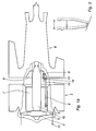
- Figure 2 shows an example of how a device for moving the compressor part 4 in the axial direction away from and towards the turbine part 1 can be designed.
- a piston 9 of conventional type is arranged at the inlet housing 8 of the compressor part 4.
- the piston is adapted to influence a control arm 10.
- the control arm 10 is fixed to an eccentric bolt 11 by means of a pin 12.
- the eccentric bolt 11 in its turn is rotatably attached to a bracket 13 fixed to the inlet housing 8.
- Via a cylindrical shaft 14, the rod 6 is journalled in the eccentric bolt.
- the shaft 14 has its centre of rotation displaced in relation to the centre of rotation of the eccentric bolt 11.
- Figure 1 also shows how the stator housing 15 of the turbine part 1, at that part which surrounds the turbine disc 2, is conically shaped with its largest cone diameter facing the outlet housing 7.
- This conical part of the stator housing 15 is referred to as the stator cone 16.
- the tip angle of the blades 5 substantially corresponds to the cone angle of the stator housing 15.
- the piston 9 When the machine has become heated after a start or after a load increase, the piston 9 is caused to be extended whereby the compressor part 4 with the rotor shaft 3 and the turbine disc 2 is moved towards the interior of the stator cone 16 and the clearance is reduced.
- the operation of the piston 9, for control of the blade tip clearance, can be performed either manually or automatically.
- Extension of the piston 9 may, for example, take place after a certain period of time after a start or when a certain power has been attained.
- Shortening of the piston 9 may, for example, take place in connection with a stop impulse being given to the machine.
- stator housing 15 is then conically shaped in the entire area around the turbine discs 2, that is, from the first to the last turbine stage.
- the invention is also applicable to machines with an integrated turbine and compressor part 1, 4, where the rotor shaft 3 is journalled outside the turbine 1 and the compressor 4.
- the invention is, of course, also applicable to machines with the stator cone 16 facing in the other direction as compared with the embodiment described.
Landscapes
- Engineering & Computer Science (AREA)
- Mechanical Engineering (AREA)
- General Engineering & Computer Science (AREA)
- Structures Of Non-Positive Displacement Pumps (AREA)
- Turbine Rotor Nozzle Sealing (AREA)
- Control Of Positive-Displacement Air Blowers (AREA)
Abstract
Description
- The invention relates to a rotating machine comprising a turbine part with at least one turbine disc attached to a rotor shaft where the outer part of the turbine disc in the form of a blade ring cooperates with a stator housing and where the turbine disc is connected via the rotor shaft to the rotor shaft of a compressor part.
- It is very important for the efficiency and performance of the turbine part that the distance, the clearance between the blade tips of the turbine disc and the stator housing of the turbine part, is as small as possible. This applies particularly to the continuous operating state in which the turbine is intended to be run. During start-up and load changes, the requirement for efficiency can be lowered.
- The elements comprised by the turbine part, for example rotor shaft, blades and stator housing, are heated and cooled differently rapidly during non-steady states, for example during start-up and load increases and during stop and load reductions. This is due to the fact that the elements have different mass and that they are influenced to a varying extent by the hot gas flow which passes through the turbine part. The heating of the elements results in linear expansion and deformations, which means that clearances between rotating and static elements during non-steady states are influenced.
- During the non-steady states, the blade tip clearance is reduced and can be completely eliminated if, in cold or in heated condition, it is chosen too small. This leads to contact and seizure, which is unacceptable. To avoid contact between rotating and static parts, a clearance between the blade tips and the turbine housing is chosen which is sufficiently large to prevent blade tip contact during start, stop and load changes and which is sufficiently small during continuous operation to prevent an unacceptably low efficiency.
- The clearance between the blade tips and the stator housing must thus be chosen on the basis of the operating state which gives the smallest permissible clearance taking into account the uneven temperature distribution, the extension of the blades because of the centrifugal force, etc.
- One way of reducing the blade tip clearance during continuous operation is to design the turbine such that expansion and deformation because of the temperature can be controlled by distributing the mass in the turbine such that movements and deformations are overcome or redistributed.
- Another way is to introduce operating restrictions to avoid the most difficult operating states which are determining for the clearance between the blade tips and the stator housing.
- Thus, the problem is to dimension the clearance between the blade tips and the stator housing so as to obtain the best possible performance and efficiency without the risk of blade tip contact with the stator housing arising, especially during start-up, stop and load changes, and without the clearance becoming unnecessarily large.
- A device for adapting the blade tip clearance to different operating conditions in a power gas turbine is known from the document US-A-4 149 826, corresponding to SE-B-403 393.
- The invention aims to provide a method and a device for controlling the blade tip clearance, that is, control of the clearance between the blade tips of a turbine and a turbine stator housing in a rotating machine. The control is performed such that the clearance during start-up, stop and load changes is larger than during continuous operation to obtain better performance and a higher efficiency without the risk of blade tip contact during start-up, stop and load changes.
- The invention comprises a method and a device, as defined in
claims 1 and 3, respectively for moving the turbine disc/turbine discs out of the stator cone during stop and load changes, such that the clearance between the blade tips and the stator housing is increased. This clearance will be referred to in the following as the blade tip clearance. - The machine comprises a turbine part and a compressor part, the turbine part comprising a stator housing, a rotor shaft which is rotatably journalled in the stator housing and which has at least one turbine disc with blades, the rotor shaft being secured to a rotor shaft comprised by the compressor part so as to obtain a common rotor shaft. The common rotor shaft is axially journalled in the compressor part.
- At their outer parts the turbine discs are provided with blades, which at their outer parts are angled at an angle coinciding with the cone angle of the stator housing. The conical part of the stator housing will be referred to in the following as the stator cone.
- Due to the angularity of the blade tips and of the stator cone, the clearance between the blades and the stator housing may be influenced when the rotor shaft is axially displaced. To bring about this axial displacement between the rotor shaft and the stator housing, the following solution can be used.
- The compressor part is mounted such that it can be displaced in the axial direction whereas the turbine housing is secured to a base. The axial displacement of the turbine discs with the blades is brought about by displacing the compressor part in the axial direction whereby the axial fixing of the interconnected rotors in the compressor part results in the turbine disc with the blades being displaced in the same axial direction as the compressor part.
- In case of a load increase, for example, the compressor part is displaced in the axial direction whereby also the rotor shaft is displaced axially such that the blade tip clearance is increased. When the machine has become thoroughly hot, the compressor part is displaced such that a minimum blade tip clearance is obtained. In case of renewed load change, the blade tip clearance is again enlarged, and during subsequent continuous operation it is again set at the minimum clearance.
- The advantage of the invention is thus that the blade tip clearance can be controlled in a simple manner during operation, thus solving the problem with too large and too small clearances.
- Figure 1 schematically shows a partial axial section through a turbine part and a compressor part to which the invention is applied.
- Figure 2 schematically shows various views of a device for moving the compressor part towards and away from the turbine part. Figure 2b shows a section according to b-b in Figure 2a, Figure 2c shows a section according to c-c in Figure 2a and Figure 2d shows a section d-d according to Figure 2c.
- Figure 3 shows in an axial section the clearance between a stator cone and a blade tip.
- Figure 1 shows a rotating machine with a
turbine part 1 in which aturbine disc 2 is arranged. Theturbine disc 2 is secured, via a rotor shaft, to the rotor shaft of acompressor part 4 which is separate from the turbine part, the latter rotor shaft forming a common rotor shaft 3 which is axially journalled in thecompressor part 4. At its outer part theturbine disc 2 is provided with blades 5. Thecompressor part 4 is pendantly supported (not shown) at its front and rear ends enabling it to be pushed in the axial direction. The machine is divided between theoutlet housing 7 of theturbine part 1 and theinlet housing 8 of thecompressor part 4. - One or more, preferably two diametrically placed,
axial rods 6 are adapted to interconnect thecompressor part 4 and theturbine part 1. Therods 6 are attached in theoutlet housing 7 and in theinlet housing 8. - Figure 2 shows an example of how a device for moving the
compressor part 4 in the axial direction away from and towards theturbine part 1 can be designed. - At the
inlet housing 8 of thecompressor part 4, apiston 9 of conventional type is arranged. The piston is adapted to influence acontrol arm 10. Thecontrol arm 10 is fixed to aneccentric bolt 11 by means of apin 12. Theeccentric bolt 11 in its turn is rotatably attached to abracket 13 fixed to theinlet housing 8. Via acylindrical shaft 14, therod 6 is journalled in the eccentric bolt. Theshaft 14 has its centre of rotation displaced in relation to the centre of rotation of theeccentric bolt 11. - When the
piston 9 is shortened, thecontrol arm 10 is rotated around the centre of theshaft 14. During the rotating movement, theeccentric bolt 11 is moved from the centre of theshaft 14 because of the eccentricity of the eccentric bolt. Since thecontrol arm 10 via therod 6, which is also journalled around theshaft 14, is fixedly journalled in theoutlet housing 7 of theturbine part 1 whereas thebracket 13 is fixed to the axiallydisplaceable compressor part 4, thecompressor part 4 is pushed in an axial direction away from theturbine part 1. - Figure 1 also shows how the stator housing 15 of the
turbine part 1, at that part which surrounds theturbine disc 2, is conically shaped with its largest cone diameter facing theoutlet housing 7. This conical part of thestator housing 15 is referred to as thestator cone 16. The tip angle of the blades 5 substantially corresponds to the cone angle of thestator housing 15. When theturbine disc 2 is caused to be moved in a direction towards theoutlet housing 7 of theturbine part 1, the clearance between the tips of the guide vanes 5 and thestator cone 16 will increase (see Figure 3). With theturbine disc 2 in this position, it is suitable to start and stop the machine and to carry out load changes. - When the machine has become heated after a start or after a load increase, the
piston 9 is caused to be extended whereby thecompressor part 4 with the rotor shaft 3 and theturbine disc 2 is moved towards the interior of thestator cone 16 and the clearance is reduced. - The operation of the
piston 9, for control of the blade tip clearance, can be performed either manually or automatically. Extension of thepiston 9 may, for example, take place after a certain period of time after a start or when a certain power has been attained. Shortening of thepiston 9 may, for example, take place in connection with a stop impulse being given to the machine. - It is, of course, possible also to utilize the invention in
turbines 1 with more than one turbine stage. Thestator housing 15 is then conically shaped in the entire area around theturbine discs 2, that is, from the first to the last turbine stage. - In the embodiment a machine which is divided between the
turbine part 1 and thecompressor part 4 has been described. - However, the invention is also applicable to machines with an integrated turbine and
compressor part turbine 1 and thecompressor 4. The invention is, of course, also applicable to machines with thestator cone 16 facing in the other direction as compared with the embodiment described.
Claims (7)
- A method for controlling the blade tip clearance in a rotating machine, which machine comprises a turbine part (1) and a compressor part (4), wherein the turbine part comprises a stator housing (15), a rotor shaft, rotatably journalled in the stator housing, with at least one turbine disc (2) with blades (5) fixedly arranged on said rotor shaft, wherein the rotor shaft is secured to a rotor shaft comprised by the compressor part such that a common rotor shaft (3) is obtained, wherein the stator housing is formed with a stator cone (16), wherein the blade tips have an angle which substantially corresponds to the angle of the stator cone, and wherein the rotor shaft and the stator housing are displaceable in relation to each other, characterized in that the rotor shaft (3) is axially journalled in the compressor part and that the compressor part, including the rotor shaft and the turbine disc/turbine discs, is displaced axially in relation to the stator housing.
- A method according to claim 1, characterized in that the compressor part in case of load changes is displaced axially such that the blades are moved out of the stator cone and the blade tip clearance is increased, and that the compressor part during continuous operation is displaced axially such that the turbine disc is moved into the stator cone and the blade tip clearance is reduced.
- A device for controlling the blade tip clearance in a rotating machine, which machine comprises a turbine part (1) and a compressor part (4), wherein the turbine part comprises a stator housing (15), a rotor shaft, rotatably journalled in the stator housing, with at least one turbine disc (2) with blades (5) fixedly arranged on said rotor shaft, wherein the rotor shaft is secured to a rotor shaft comprised by the compressor part such that a common rotor shaft (3) is obtained, wherein the stator housing is formed with a stator cone (16), wherein the blade tips have an angle which substantially corresponds to the angle of the stator cone, and wherein the rotor shaft and the stator housing are displaceable in relation to each other, characterized in that the rotor shaft is axially journalled in the compressor housing and that the compressor part is pendantly suspended such that displacement thereof, including the rotor shaft and the turbine disc/turbine discs, in the axial direction is possible.
- A device according to claim 3, characterized in that at least one axial rod (6) is adapted to interconnect the turbine part and the compressor part.
- A device according to claim 3 or 4, characterized in that a piston (9) is adapted to displace, in the axial direction, the compressor part towards and away from the turbine part.
- A device according to claim 3, 4 or 5, characterized in that a control arm (10), via a pin (12), is fixed to an eccentric bolt (11) which is rotatably attached to a bracket (13) and that the control arm, the eccentric bolt, the bracket and the rod (6) are journalled around a shaft (14).
- A device according to claim 5 or 6, characterized in that the piston is adapted, via the eccentric bolt (11), to cause the bracket (13) to displace the compressor housing in the axial direction via the rod (6).
Applications Claiming Priority (3)
| Application Number | Priority Date | Filing Date | Title |
|---|---|---|---|
| SE9201061A SE470218B (en) | 1992-04-01 | 1992-04-01 | Method and apparatus for controlling paddle top play of a rotary machine |
| SE9201061 | 1992-04-01 | ||
| PCT/SE1993/000224 WO1993020335A1 (en) | 1992-04-01 | 1993-03-16 | A method and a device in a rotating machine |
Publications (2)
| Publication Number | Publication Date |
|---|---|
| EP0633977A1 EP0633977A1 (en) | 1995-01-18 |
| EP0633977B1 true EP0633977B1 (en) | 1996-07-03 |
Family
ID=20385851
Family Applications (1)
| Application Number | Title | Priority Date | Filing Date |
|---|---|---|---|
| EP93908212A Expired - Lifetime EP0633977B1 (en) | 1992-04-01 | 1993-03-16 | A method and a device in a rotating machine |
Country Status (9)
| Country | Link |
|---|---|
| US (1) | US5330320A (en) |
| EP (1) | EP0633977B1 (en) |
| JP (1) | JP3218245B2 (en) |
| CN (1) | CN1035400C (en) |
| DE (1) | DE69303477T2 (en) |
| ES (1) | ES2091602T3 (en) |
| FI (1) | FI101996B (en) |
| SE (1) | SE470218B (en) |
| WO (1) | WO1993020335A1 (en) |
Cited By (1)
| Publication number | Priority date | Publication date | Assignee | Title |
|---|---|---|---|---|
| US9291070B2 (en) | 2010-12-03 | 2016-03-22 | Pratt & Whitney Canada Corp. | Gas turbine rotor containment |
Families Citing this family (24)
| Publication number | Priority date | Publication date | Assignee | Title |
|---|---|---|---|---|
| FR2722836B1 (en) * | 1994-07-20 | 1996-08-30 | Snecma | TURBOMACHINE PROVIDED WITH MEANS FOR ADJUSTING THE RADIAL GAME BETWEEN ROTOR AND STATOR |
| US6092986A (en) * | 1996-07-24 | 2000-07-25 | Siemens Aktiengesellschaft | Turbine plant having a thrust element, and thrust element |
| WO1999028598A1 (en) * | 1997-12-02 | 1999-06-10 | Siemens Aktiengesellschaft | Turbomachine and method for adjusting the width of a radial gap |
| WO2000028190A1 (en) | 1998-11-11 | 2000-05-18 | Siemens Aktiengesellschaft | Shaft bearing for a turbo-machine, turbo-machine and method for operating a turbo-machine |
| EP1249579A1 (en) * | 2001-04-11 | 2002-10-16 | Siemens Aktiengesellschaft | Steam turbine |
| US6692222B2 (en) * | 2002-05-14 | 2004-02-17 | The Board Of Trustees Of The Leland Stanford Junior University | Micro gas turbine engine with active tip clearance control |
| US7234918B2 (en) | 2004-12-16 | 2007-06-26 | Siemens Power Generation, Inc. | Gap control system for turbine engines |
| US8011883B2 (en) | 2004-12-29 | 2011-09-06 | United Technologies Corporation | Gas turbine engine blade tip clearance apparatus and method |
| US7341426B2 (en) * | 2004-12-29 | 2008-03-11 | United Technologies Corporation | Gas turbine engine blade tip clearance apparatus and method |
| US7407369B2 (en) * | 2004-12-29 | 2008-08-05 | United Technologies Corporation | Gas turbine engine blade tip clearance apparatus and method |
| DE102005048982A1 (en) | 2005-10-13 | 2007-04-19 | Mtu Aero Engines Gmbh | Apparatus and method for axially displacing a turbine rotor |
| CA2639971A1 (en) * | 2006-01-25 | 2007-08-02 | Team Medical, Llc | Coating suitable for surgical instruments |
| US7909566B1 (en) * | 2006-04-20 | 2011-03-22 | Florida Turbine Technologies, Inc. | Rotor thrust balance activated tip clearance control system |
| US7686569B2 (en) * | 2006-12-04 | 2010-03-30 | Siemens Energy, Inc. | Blade clearance system for a turbine engine |
| US20100079136A1 (en) * | 2008-09-29 | 2010-04-01 | Rosemount Aerospace Inc. | Blade tip clearance measurement sensor and method for gas turbine engines |
| DE102010045851A1 (en) * | 2010-09-17 | 2012-03-22 | Mtu Aero Engines Gmbh | Turbo-machine e.g. turbine stage of gas turbine of aircraft engine, has housing control unit for displacement of housing portions against each other and/or bearing control unit for displacement of housing and rotor shaft against each other |
| DE102011003841A1 (en) * | 2011-02-09 | 2012-08-09 | Siemens Aktiengesellschaft | Turbine with relatively adjustable rotor and turbine housing |
| KR101504848B1 (en) | 2011-03-31 | 2015-03-20 | 미츠비시 쥬고교 가부시키가이샤 | Steam turbine casing position adjusting apparatus |
| US9109608B2 (en) | 2011-12-15 | 2015-08-18 | Siemens Energy, Inc. | Compressor airfoil tip clearance optimization system |
| DE102012213016A1 (en) * | 2012-07-25 | 2014-01-30 | Siemens Aktiengesellschaft | Method for minimizing the gap between a rotor and a housing |
| WO2015065597A2 (en) * | 2013-10-02 | 2015-05-07 | United Technologies Corporation | Translating compressor and turbine rotors for clearance control |
| US9593589B2 (en) | 2014-02-28 | 2017-03-14 | General Electric Company | System and method for thrust bearing actuation to actively control clearance in a turbo machine |
| EP3396114A1 (en) | 2017-04-28 | 2018-10-31 | Siemens Aktiengesellschaft | Turbomachinery and corresponding method of operating |
| US12055072B2 (en) | 2020-02-06 | 2024-08-06 | Siemens Energy Global GmbH & Co. KG | Method for modifying a single shaft combined cycle power plant |
Family Cites Families (9)
| Publication number | Priority date | Publication date | Assignee | Title |
|---|---|---|---|---|
| US1823310A (en) * | 1929-05-23 | 1931-09-15 | Westinghouse Electric & Mfg Co | Elastic fluid turbine |
| US2762559A (en) * | 1954-09-23 | 1956-09-11 | Westinghouse Electric Corp | Axial flow compressor with axially adjustable rotor |
| US3227418A (en) * | 1963-11-04 | 1966-01-04 | Gen Electric | Variable clearance seal |
| SE403393B (en) * | 1976-07-05 | 1978-08-14 | Stal Laval Turbin Ab | GAS TURBINE |
| GB2042646B (en) * | 1979-02-20 | 1982-09-22 | Rolls Royce | Rotor blade tip clearance control for gas turbine engine |
| US4332523A (en) * | 1979-05-25 | 1982-06-01 | Teledyne Industries, Inc. | Turbine shroud assembly |
| GB2050524B (en) * | 1979-06-06 | 1982-10-20 | Rolls Royce | Turbine stator shroud assembly |
| US5051061A (en) * | 1988-12-23 | 1991-09-24 | Asea Brown Boveri Ltd. | Multi-cylinder steam turbine set |
| US5203673A (en) * | 1992-01-21 | 1993-04-20 | Westinghouse Electric Corp. | Tip clearance control apparatus for a turbo-machine blade |
-
1992
- 1992-04-01 SE SE9201061A patent/SE470218B/en not_active IP Right Cessation
-
1993
- 1993-03-16 ES ES93908212T patent/ES2091602T3/en not_active Expired - Lifetime
- 1993-03-16 JP JP51735493A patent/JP3218245B2/en not_active Expired - Fee Related
- 1993-03-16 WO PCT/SE1993/000224 patent/WO1993020335A1/en active IP Right Grant
- 1993-03-16 EP EP93908212A patent/EP0633977B1/en not_active Expired - Lifetime
- 1993-03-16 DE DE69303477T patent/DE69303477T2/en not_active Expired - Lifetime
- 1993-03-29 CN CN93104419.7A patent/CN1035400C/en not_active Expired - Lifetime
- 1993-03-31 US US08/040,619 patent/US5330320A/en not_active Expired - Lifetime
-
1994
- 1994-09-30 FI FI944551A patent/FI101996B/en active
Cited By (1)
| Publication number | Priority date | Publication date | Assignee | Title |
|---|---|---|---|---|
| US9291070B2 (en) | 2010-12-03 | 2016-03-22 | Pratt & Whitney Canada Corp. | Gas turbine rotor containment |
Also Published As
| Publication number | Publication date |
|---|---|
| EP0633977A1 (en) | 1995-01-18 |
| SE9201061L (en) | 1993-10-02 |
| JPH07505202A (en) | 1995-06-08 |
| SE470218B (en) | 1993-12-06 |
| CN1035400C (en) | 1997-07-09 |
| US5330320A (en) | 1994-07-19 |
| JP3218245B2 (en) | 2001-10-15 |
| DE69303477D1 (en) | 1996-08-08 |
| ES2091602T3 (en) | 1996-11-01 |
| FI944551A (en) | 1994-11-30 |
| DE69303477T2 (en) | 1997-05-28 |
| SE9201061D0 (en) | 1992-04-01 |
| FI944551A0 (en) | 1994-09-30 |
| FI101996B1 (en) | 1998-09-30 |
| WO1993020335A1 (en) | 1993-10-14 |
| FI101996B (en) | 1998-09-30 |
| CN1088655A (en) | 1994-06-29 |
Similar Documents
| Publication | Publication Date | Title |
|---|---|---|
| EP0633977B1 (en) | A method and a device in a rotating machine | |
| US4363599A (en) | Clearance control | |
| US7909566B1 (en) | Rotor thrust balance activated tip clearance control system | |
| US5022817A (en) | Thermostatic control of turbine cooling air | |
| US4117669A (en) | Apparatus and method for reducing thermal stress in a turbine rotor | |
| US4773817A (en) | Labyrinth seal adjustment device for incorporation in a turbomachine | |
| EP2206888A2 (en) | Turbine power generation system and corresponding operating method | |
| DE3941174A1 (en) | TOP GAME SETTING ON TURBO MACHINES | |
| JP4773452B2 (en) | Optimal turbine stage of turbine apparatus and method for configuring turbine stage | |
| CN1755080B (en) | Nose cone for a turbomachine | |
| EP0367969A1 (en) | Vane segment support and alignment arrangement for a combustion turbine | |
| DE2728190C3 (en) | Gas turbine | |
| US20030147742A1 (en) | Gas turbine impeller alignment tool and method | |
| EP2554797A2 (en) | System and method for passively controlling clearance in a gas turbine engine | |
| US20020071763A1 (en) | Device for setting the gap dimension for a turbomachine | |
| EP2198151A1 (en) | Multistage wind turbine with variable blade displacement | |
| JPS5874830A (en) | Exhaust gas turbosupercharger with bearing section arranged between turbine and compressor | |
| CZ285117B6 (en) | Axial flow turbine | |
| GB2062117A (en) | Clearance Control for Turbine Blades | |
| EP1908926A1 (en) | Turbomachine | |
| US4279570A (en) | Energy transfer machine | |
| US12055048B2 (en) | Method for rotor blade tip clearance control and rotor blade manufactured by the method | |
| JPH06159099A (en) | Axial flow fluid machinery | |
| WO1999035384A1 (en) | Revolution speed control method in gas turbine shutdown process | |
| CN214424771U (en) | Linkage ring supporting mechanism, stationary blade adjusting mechanism and air compressor |
Legal Events
| Date | Code | Title | Description |
|---|---|---|---|
| PUAI | Public reference made under article 153(3) epc to a published international application that has entered the european phase |
Free format text: ORIGINAL CODE: 0009012 |
|
| 17P | Request for examination filed |
Effective date: 19941022 |
|
| AK | Designated contracting states |
Kind code of ref document: A1 Designated state(s): DE ES FR GB IT |
|
| 17Q | First examination report despatched |
Effective date: 19950901 |
|
| GRAH | Despatch of communication of intention to grant a patent |
Free format text: ORIGINAL CODE: EPIDOS IGRA |
|
| GRAH | Despatch of communication of intention to grant a patent |
Free format text: ORIGINAL CODE: EPIDOS IGRA |
|
| GRAA | (expected) grant |
Free format text: ORIGINAL CODE: 0009210 |
|
| AK | Designated contracting states |
Kind code of ref document: B1 Designated state(s): DE ES FR GB IT |
|
| REF | Corresponds to: |
Ref document number: 69303477 Country of ref document: DE Date of ref document: 19960808 |
|
| ITF | It: translation for a ep patent filed | ||
| ET | Fr: translation filed | ||
| REG | Reference to a national code |
Ref country code: ES Ref legal event code: FG2A Ref document number: 2091602 Country of ref document: ES Kind code of ref document: T3 |
|
| PLBE | No opposition filed within time limit |
Free format text: ORIGINAL CODE: 0009261 |
|
| STAA | Information on the status of an ep patent application or granted ep patent |
Free format text: STATUS: NO OPPOSITION FILED WITHIN TIME LIMIT |
|
| 26N | No opposition filed | ||
| REG | Reference to a national code |
Ref country code: GB Ref legal event code: IF02 |
|
| PG25 | Lapsed in a contracting state [announced via postgrant information from national office to epo] |
Ref country code: DE Free format text: LAPSE BECAUSE OF NON-PAYMENT OF DUE FEES Effective date: 20111001 |
|
| PGFP | Annual fee paid to national office [announced via postgrant information from national office to epo] |
Ref country code: FR Payment date: 20120327 Year of fee payment: 20 |
|
| PGFP | Annual fee paid to national office [announced via postgrant information from national office to epo] |
Ref country code: GB Payment date: 20120312 Year of fee payment: 20 Ref country code: IT Payment date: 20120328 Year of fee payment: 20 |
|
| PGFP | Annual fee paid to national office [announced via postgrant information from national office to epo] |
Ref country code: DE Payment date: 20120518 Year of fee payment: 20 |
|
| PGFP | Annual fee paid to national office [announced via postgrant information from national office to epo] |
Ref country code: ES Payment date: 20120404 Year of fee payment: 20 |
|
| REG | Reference to a national code |
Ref country code: DE Ref legal event code: R071 Ref document number: 69303477 Country of ref document: DE |
|
| REG | Reference to a national code |
Ref country code: DE Ref legal event code: R071 Ref document number: 69303477 Country of ref document: DE |
|
| REG | Reference to a national code |
Ref country code: GB Ref legal event code: PE20 Expiry date: 20130315 |
|
| PG25 | Lapsed in a contracting state [announced via postgrant information from national office to epo] |
Ref country code: DE Free format text: LAPSE BECAUSE OF EXPIRATION OF PROTECTION Effective date: 20130319 Ref country code: GB Free format text: LAPSE BECAUSE OF EXPIRATION OF PROTECTION Effective date: 20130315 |
|
| REG | Reference to a national code |
Ref country code: ES Ref legal event code: FD2A Effective date: 20130703 |
|
| PG25 | Lapsed in a contracting state [announced via postgrant information from national office to epo] |
Ref country code: ES Free format text: LAPSE BECAUSE OF EXPIRATION OF PROTECTION Effective date: 20130317 |