EP0633813B1 - Refining element - Google Patents
Refining element Download PDFInfo
- Publication number
- EP0633813B1 EP0633813B1 EP93906917A EP93906917A EP0633813B1 EP 0633813 B1 EP0633813 B1 EP 0633813B1 EP 93906917 A EP93906917 A EP 93906917A EP 93906917 A EP93906917 A EP 93906917A EP 0633813 B1 EP0633813 B1 EP 0633813B1
- Authority
- EP
- European Patent Office
- Prior art keywords
- refining element
- refining
- holder
- attachment
- holes
- Prior art date
- Legal status (The legal status is an assumption and is not a legal conclusion. Google has not performed a legal analysis and makes no representation as to the accuracy of the status listed.)
- Expired - Lifetime
Links
- 238000007670 refining Methods 0.000 title claims abstract description 50
- 239000000463 material Substances 0.000 description 3
- 230000009172 bursting Effects 0.000 description 2
- 239000000835 fiber Substances 0.000 description 2
- 239000002657 fibrous material Substances 0.000 description 2
- 230000005484 gravity Effects 0.000 description 1
- 239000000126 substance Substances 0.000 description 1
Images
Classifications
-
- D—TEXTILES; PAPER
- D21—PAPER-MAKING; PRODUCTION OF CELLULOSE
- D21D—TREATMENT OF THE MATERIALS BEFORE PASSING TO THE PAPER-MAKING MACHINE
- D21D1/00—Methods of beating or refining; Beaters of the Hollander type
- D21D1/20—Methods of refining
- D21D1/30—Disc mills
- D21D1/306—Discs
-
- B—PERFORMING OPERATIONS; TRANSPORTING
- B02—CRUSHING, PULVERISING, OR DISINTEGRATING; PREPARATORY TREATMENT OF GRAIN FOR MILLING
- B02C—CRUSHING, PULVERISING, OR DISINTEGRATING IN GENERAL; MILLING GRAIN
- B02C7/00—Crushing or disintegrating by disc mills
- B02C7/11—Details
- B02C7/12—Shape or construction of discs
Definitions
- This invention relates to a refining element for disk refiners.
- the element is provided on its front side with working members for defibering and refining lignocellulose-containing fiber material.
- the refining element further is formed with through holes for attaching it on a holder in the refiner by means of screws. This kind of refining element is disclosed in US-A-1 599 118 and DE-A-2 315 218.
- a plurality of such refining elements are attached in the refiner in the form of a ring about each of two opposed holders, which are rotary relative to each other. Both holders can be rotated in opposed directions, or one holder can be rotary and one stationary.
- the material passes through the refining gap, which is formed between refining elements on the opposed holders.
- the material is worked simultaneously. This working normally takes place in continuous operation under high pressure end temperature, whereby the working members on the front sides of the refining elements are subjected to wear. Due to the wear, the quality of the worked fiber material deteriorates, so that the refining elements must be exchanged after a certain time. This time can amount to several months.
- the present invention offers a solution of the aforesaid problems. Its object, thus, is to design a refining element, which renders it possible to rapidly and simply remove refining elements from a holder in a disk refiner at satisfactory safety for both staff and machine equipment.
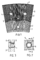
- the refining element 1 shown in Fig. 1 is formed on its front side with working members in the form of bars 2 with intermediate grooves 3. Through holes 4, usually three in number, are provided for attaching the element on the holder in the disk refiner. Said holes are located so that good abutment to the holder is obtained. The attachment is carried out by screws, which are tightened from the front side in corresponding threaded holes in the holder.
- the refining element 1 further is provided with a threaded hole 5 located centrally on the refining element, preferably close to its centre of gravity. About the hole 5 a zone 6 without bars is located. In said threaded hole 5 a covering screw 7 shall be attached in such a manner, that the zone 6 about the hole provides sufficient contact surface for the head of the covering screw 7 to be locked against the material in the refining element 1. Normally one single threaded hole 5 is sufficient, but it is, of course, possible to have two or more threaded holes. In such cases, a covering screw is to be attached in every threaded hole.
- the head of the covering screw 7 is formed so that it is located preferably 1-3 mm beneath the working surface of the bars 2.
- the screw head preferably is formed for an internal hexagon spanner.
- the covering screw 7 extends only just through the refining element and shall in operation sit in the hole 5 in order to prevent fibers to penetrate in between the refining element and holder.
- the attachment screws are loosened. They shall, however, not entirely be threaded out of the holes in the holder.
- the covering screw 7, however, is screwed out of the hole 5. Thereafter a longer screw, a bursting screw, is screwed into the hole 5.
- this bursting screw When this bursting screw arrives at the holder lying behind, it lifts at continued screwing the refining element up from the holder.
- the force achievable in this way was found sufficient for rapidly and simply loosening the refining element, which otherwise could not be loosened without great problems, see above.
- the remaining attachment screws prevent the refining element from dashing off in an uncontrolled manner when it loosens from the holder.
- the threaded hole 5 can be used for pulling out the refining element.
- the attachment screws are screwed out entirely.
- a clamp can be attached by means of long screws, which extend through attachment holes 4 of the refining element and are tightened in the holder. By means of this clamp and a longer screw to be attached in the threaded hole 5, the refining element can thereafter be pulled out.
- the clamp in this case prevents the refining element from dashing off if it loosens abruptly.
Landscapes
- Engineering & Computer Science (AREA)
- Food Science & Technology (AREA)
- Paper (AREA)
- Crystals, And After-Treatments Of Crystals (AREA)
- Mechanical Treatment Of Semiconductor (AREA)
- Addition Polymer Or Copolymer, Post-Treatments, Or Chemical Modifications (AREA)
- Constituent Portions Of Griding Lathes, Driving, Sensing And Control (AREA)
Abstract
Description
Claims (2)
- A refining element for a disk refiner, which element is provided on its front side with working members (2) and is formed with through holes (4) for its attachment on a holder in the refiner, characterized in that the refining element (1) is further provided with a centrally located threaded hole (5), which in operation is coverable from the front side by a covering screw (7), and at the exchange of refining elements is intended for a longer screw, by means of which the element (1) can be removed from the holder.
- A refining element as stated in claim 1, characterized in that the covering screw (7) extends only just through the refining element (1) and has a head, which is located 1-3 mm beneath the surface of the working members (2).
Applications Claiming Priority (3)
| Application Number | Priority Date | Filing Date | Title |
|---|---|---|---|
| SE9201116A SE470089B (en) | 1992-04-08 | 1992-04-08 | Grinding elements for a disc refiner |
| SE9201116 | 1992-04-08 | ||
| PCT/SE1993/000059 WO1993020941A1 (en) | 1992-04-08 | 1993-01-28 | Refining element |
Publications (2)
| Publication Number | Publication Date |
|---|---|
| EP0633813A1 EP0633813A1 (en) | 1995-01-18 |
| EP0633813B1 true EP0633813B1 (en) | 1998-10-14 |
Family
ID=20385895
Family Applications (1)
| Application Number | Title | Priority Date | Filing Date |
|---|---|---|---|
| EP93906917A Expired - Lifetime EP0633813B1 (en) | 1992-04-08 | 1993-01-28 | Refining element |
Country Status (12)
| Country | Link |
|---|---|
| US (1) | US5526992A (en) |
| EP (1) | EP0633813B1 (en) |
| AT (1) | ATE172133T1 (en) |
| AU (1) | AU662663B2 (en) |
| CA (1) | CA2130659C (en) |
| DE (1) | DE69321586T2 (en) |
| ES (1) | ES2121997T3 (en) |
| FI (1) | FI100385B (en) |
| NO (1) | NO303718B1 (en) |
| NZ (1) | NZ249989A (en) |
| SE (1) | SE470089B (en) |
| WO (1) | WO1993020941A1 (en) |
Families Citing this family (11)
| Publication number | Priority date | Publication date | Assignee | Title |
|---|---|---|---|---|
| US5979809A (en) * | 1998-03-13 | 1999-11-09 | J & L Fiber Services Inc | Refiner disc removal method and device |
| US6935589B1 (en) * | 1998-08-17 | 2005-08-30 | Norwalk Industrial Components, Llc | Papermaking refiner plates and method of manufacture |
| SE526401C2 (en) * | 2004-01-21 | 2005-09-06 | Metso Paper Inc | Refining elements |
| DE202004001620U1 (en) * | 2004-02-04 | 2004-04-08 | Voith Paper Patent Gmbh | Grinding sets for paper pulp |
| US7350728B2 (en) * | 2004-08-17 | 2008-04-01 | Glv Finance Hungary Kft. | Refining plate attached to a head in a pulp refiner |
| RU2288313C2 (en) * | 2004-12-29 | 2006-11-27 | Открытое Акционерное Общество "Канский Машиностроительный завод "Сегмент" | Milling set for disk mill |
| MXNL05000017A (en) * | 2005-02-22 | 2006-03-23 | Julio Antonio Trevino Morales | Refining segment and manufacturing process thereof. |
| US8143996B2 (en) * | 2007-01-08 | 2012-03-27 | The Curators Of The University Of Missouri | Decentralized radio frequency identification system |
| FI122889B (en) * | 2010-12-31 | 2012-08-31 | Upm Kymmene Corp | Method and apparatus for producing nanocellulose |
| SE537820C2 (en) * | 2014-02-10 | 2015-10-27 | Valmet Oy | refiner |
| US11660661B2 (en) | 2017-01-12 | 2023-05-30 | Valmet Ab | Method for producing a refiner disc segment |
Family Cites Families (10)
| Publication number | Priority date | Publication date | Assignee | Title |
|---|---|---|---|---|
| US272642A (en) * | 1883-02-20 | Half to howard h | ||
| US2119768A (en) * | 1938-06-07 | Grinding plate | ||
| US25243A (en) * | 1859-08-30 | Quartz-crushing machine | ||
| US3459379A (en) * | 1967-01-18 | 1969-08-05 | Beloit Corp | Mechanical pulping apparatus |
| SE344423B (en) * | 1971-06-07 | 1972-04-17 | A Bayev | |
| US3910511A (en) * | 1974-05-20 | 1975-10-07 | Westvaco Corp | Open discharge pulp refiner |
| US4201350A (en) * | 1977-06-20 | 1980-05-06 | Brunswick Industrial Supply Company | Reconditioned sand muller |
| SE8403543D0 (en) * | 1984-07-04 | 1984-07-04 | Sca Development Ab | SEE WHILE PREPARING MOLD SEGMENTS |
| US4681270A (en) * | 1985-11-08 | 1987-07-21 | Sullivan Corporation | Manufactured refining element |
| US5383617A (en) * | 1993-10-21 | 1995-01-24 | Deuchars; Ian | Refiner plates with asymmetric inlet pattern |
-
1992
- 1992-04-08 SE SE9201116A patent/SE470089B/en not_active IP Right Cessation
-
1993
- 1993-01-28 AT AT93906917T patent/ATE172133T1/en not_active IP Right Cessation
- 1993-01-28 US US08/318,611 patent/US5526992A/en not_active Expired - Lifetime
- 1993-01-28 ES ES93906917T patent/ES2121997T3/en not_active Expired - Lifetime
- 1993-01-28 WO PCT/SE1993/000059 patent/WO1993020941A1/en not_active Ceased
- 1993-01-28 NZ NZ249989A patent/NZ249989A/en unknown
- 1993-01-28 EP EP93906917A patent/EP0633813B1/en not_active Expired - Lifetime
- 1993-01-28 AU AU51092/93A patent/AU662663B2/en not_active Ceased
- 1993-01-28 CA CA002130659A patent/CA2130659C/en not_active Expired - Fee Related
- 1993-01-28 DE DE69321586T patent/DE69321586T2/en not_active Expired - Fee Related
-
1994
- 1994-10-07 FI FI944702A patent/FI100385B/en active
- 1994-10-07 NO NO943802A patent/NO303718B1/en not_active IP Right Cessation
Also Published As
| Publication number | Publication date |
|---|---|
| FI944702L (en) | 1994-10-07 |
| SE9201116D0 (en) | 1992-04-08 |
| CA2130659A1 (en) | 1993-10-09 |
| NO943802L (en) | 1994-10-07 |
| AU5109293A (en) | 1993-11-18 |
| NZ249989A (en) | 1996-06-25 |
| SE470089B (en) | 1993-11-08 |
| ATE172133T1 (en) | 1998-10-15 |
| NO303718B1 (en) | 1998-08-24 |
| CA2130659C (en) | 2003-08-19 |
| US5526992A (en) | 1996-06-18 |
| DE69321586D1 (en) | 1998-11-19 |
| FI944702A0 (en) | 1994-10-07 |
| EP0633813A1 (en) | 1995-01-18 |
| DE69321586T2 (en) | 1999-03-04 |
| NO943802D0 (en) | 1994-10-07 |
| SE9201116L (en) | 1993-10-09 |
| WO1993020941A1 (en) | 1993-10-28 |
| AU662663B2 (en) | 1995-09-07 |
| ES2121997T3 (en) | 1998-12-16 |
| FI100385B (en) | 1997-11-28 |
Similar Documents
| Publication | Publication Date | Title |
|---|---|---|
| CA2130659C (en) | Refining element | |
| DE4322401C2 (en) | Attachment of a cutting tool to a cutting body | |
| US4828327A (en) | Bit holder for miner | |
| JP6016812B2 (en) | Chisel holder for ground processing machine | |
| EP0698437A1 (en) | Positively fixed cutting insert | |
| JP5984832B2 (en) | Chisel holder | |
| EP0228002B1 (en) | Rotating beater for comminuting matter | |
| WO2003006165A1 (en) | A tooth cap assembly | |
| EP1369603B1 (en) | Screw element, and place of junction to rotate the screw | |
| AU2011240218B2 (en) | Blow bar for an impact crusher, in particular a rotary impact crusher | |
| JPS61153149A (en) | Wast treatment unit | |
| BRPI0304048B1 (en) | Cutter Ring, Cutter Ring and Method for Maintaining and Repairing a Cutter Ring | |
| DE3490592T1 (en) | Disintegrator | |
| US5979809A (en) | Refiner disc removal method and device | |
| US6474208B1 (en) | Cutting device with detachable cutter head for cutting sheet material length-wise | |
| DE69105389T2 (en) | Method and device for changing a knife in a disk chipper. | |
| DE202005007551U1 (en) | Screw fastener to hold clothing at a grinder carrier, to grind fibers in a refiner, has recesses in the screw head to be gripped by a tool for removal when the head is worn | |
| FI70819B (en) | KNIVHAOLLARE | |
| AT398711B (en) | CYLINDRICAL ROTOR | |
| WO2007096155A1 (en) | Crushing tool | |
| CA2375059A1 (en) | A method and means for measuring stress forces in refiners | |
| GB2163377A (en) | A metal-cutting tool | |
| RU1836195C (en) | Assembled cutting instrument | |
| NL9201947A (en) | Device for plucking poultry | |
| KR19980059744A (en) | Cutting tool and its fastening structure |
Legal Events
| Date | Code | Title | Description |
|---|---|---|---|
| PUAI | Public reference made under article 153(3) epc to a published international application that has entered the european phase |
Free format text: ORIGINAL CODE: 0009012 |
|
| 17P | Request for examination filed |
Effective date: 19940813 |
|
| AK | Designated contracting states |
Kind code of ref document: A1 Designated state(s): AT DE ES FR IT SE |
|
| 17Q | First examination report despatched |
Effective date: 19970325 |
|
| GRAG | Despatch of communication of intention to grant |
Free format text: ORIGINAL CODE: EPIDOS AGRA |
|
| GRAG | Despatch of communication of intention to grant |
Free format text: ORIGINAL CODE: EPIDOS AGRA |
|
| GRAH | Despatch of communication of intention to grant a patent |
Free format text: ORIGINAL CODE: EPIDOS IGRA |
|
| GRAH | Despatch of communication of intention to grant a patent |
Free format text: ORIGINAL CODE: EPIDOS IGRA |
|
| GRAA | (expected) grant |
Free format text: ORIGINAL CODE: 0009210 |
|
| AK | Designated contracting states |
Kind code of ref document: B1 Designated state(s): AT DE ES FR IT SE |
|
| REF | Corresponds to: |
Ref document number: 172133 Country of ref document: AT Date of ref document: 19981015 Kind code of ref document: T |
|
| REF | Corresponds to: |
Ref document number: 69321586 Country of ref document: DE Date of ref document: 19981119 |
|
| ET | Fr: translation filed | ||
| REG | Reference to a national code |
Ref country code: ES Ref legal event code: FG2A Ref document number: 2121997 Country of ref document: ES Kind code of ref document: T3 |
|
| PLBE | No opposition filed within time limit |
Free format text: ORIGINAL CODE: 0009261 |
|
| STAA | Information on the status of an ep patent application or granted ep patent |
Free format text: STATUS: NO OPPOSITION FILED WITHIN TIME LIMIT |
|
| 26N | No opposition filed | ||
| PGFP | Annual fee paid to national office [announced via postgrant information from national office to epo] |
Ref country code: ES Payment date: 20040123 Year of fee payment: 12 |
|
| PG25 | Lapsed in a contracting state [announced via postgrant information from national office to epo] |
Ref country code: IT Free format text: LAPSE BECAUSE OF NON-PAYMENT OF DUE FEES Effective date: 20050128 |
|
| PG25 | Lapsed in a contracting state [announced via postgrant information from national office to epo] |
Ref country code: ES Free format text: LAPSE BECAUSE OF NON-PAYMENT OF DUE FEES Effective date: 20050129 |
|
| REG | Reference to a national code |
Ref country code: ES Ref legal event code: FD2A Effective date: 20050129 |
|
| PGFP | Annual fee paid to national office [announced via postgrant information from national office to epo] |
Ref country code: AT Payment date: 20090128 Year of fee payment: 17 |
|
| PGFP | Annual fee paid to national office [announced via postgrant information from national office to epo] |
Ref country code: DE Payment date: 20090126 Year of fee payment: 17 |
|
| PGFP | Annual fee paid to national office [announced via postgrant information from national office to epo] |
Ref country code: FR Payment date: 20090130 Year of fee payment: 17 |
|
| REG | Reference to a national code |
Ref country code: FR Ref legal event code: ST Effective date: 20100930 |
|
| PG25 | Lapsed in a contracting state [announced via postgrant information from national office to epo] |
Ref country code: FR Free format text: LAPSE BECAUSE OF NON-PAYMENT OF DUE FEES Effective date: 20100201 |
|
| PG25 | Lapsed in a contracting state [announced via postgrant information from national office to epo] |
Ref country code: DE Free format text: LAPSE BECAUSE OF NON-PAYMENT OF DUE FEES Effective date: 20100803 Ref country code: AT Free format text: LAPSE BECAUSE OF NON-PAYMENT OF DUE FEES Effective date: 20100128 |
|
| PGFP | Annual fee paid to national office [announced via postgrant information from national office to epo] |
Ref country code: SE Payment date: 20120124 Year of fee payment: 20 |
|
| REG | Reference to a national code |
Ref country code: SE Ref legal event code: EUG |