EP0633568B1 - Cartridge manipulation and reference system for magnetic tape recorder - Google Patents
Cartridge manipulation and reference system for magnetic tape recorder Download PDFInfo
- Publication number
- EP0633568B1 EP0633568B1 EP93118134A EP93118134A EP0633568B1 EP 0633568 B1 EP0633568 B1 EP 0633568B1 EP 93118134 A EP93118134 A EP 93118134A EP 93118134 A EP93118134 A EP 93118134A EP 0633568 B1 EP0633568 B1 EP 0633568B1
- Authority
- EP
- European Patent Office
- Prior art keywords
- bridge
- cassette
- tape
- magnetic
- recorder
- Prior art date
- Legal status (The legal status is an assumption and is not a legal conclusion. Google has not performed a legal analysis and makes no representation as to the accuracy of the status listed.)
- Expired - Lifetime
Links
- 238000000034 method Methods 0.000 claims description 7
- 230000003213 activating effect Effects 0.000 claims 1
- 239000000428 dust Substances 0.000 description 21
- 230000007246 mechanism Effects 0.000 description 20
- 230000000669 biting effect Effects 0.000 description 5
- 239000000463 material Substances 0.000 description 4
- 230000032258 transport Effects 0.000 description 4
- 230000009471 action Effects 0.000 description 3
- 230000004913 activation Effects 0.000 description 3
- 230000006835 compression Effects 0.000 description 2
- 238000007906 compression Methods 0.000 description 2
- 238000003780 insertion Methods 0.000 description 2
- 230000037431 insertion Effects 0.000 description 2
- 238000005452 bending Methods 0.000 description 1
- 230000004048 modification Effects 0.000 description 1
- 238000012986 modification Methods 0.000 description 1
- 230000008569 process Effects 0.000 description 1
- 230000001681 protective effect Effects 0.000 description 1
- 238000005086 pumping Methods 0.000 description 1
- 230000009467 reduction Effects 0.000 description 1
- 239000011435 rock Substances 0.000 description 1
Images



Classifications
-
- G—PHYSICS
- G11—INFORMATION STORAGE
- G11B—INFORMATION STORAGE BASED ON RELATIVE MOVEMENT BETWEEN RECORD CARRIER AND TRANSDUCER
- G11B15/00—Driving, starting or stopping record carriers of filamentary or web form; Driving both such record carriers and heads; Guiding such record carriers or containers therefor; Control thereof; Control of operating function
- G11B15/675—Guiding containers, e.g. loading, ejecting cassettes
- G11B15/6751—Guiding containers, e.g. loading, ejecting cassettes with movement of the cassette parallel to its main side, i.e. front loading
- G11B15/67521—Guiding containers, e.g. loading, ejecting cassettes with movement of the cassette parallel to its main side, i.e. front loading of cassette with internal belt drive
-
- G—PHYSICS
- G11—INFORMATION STORAGE
- G11B—INFORMATION STORAGE BASED ON RELATIVE MOVEMENT BETWEEN RECORD CARRIER AND TRANSDUCER
- G11B15/00—Driving, starting or stopping record carriers of filamentary or web form; Driving both such record carriers and heads; Guiding such record carriers or containers therefor; Control thereof; Control of operating function
- G11B15/675—Guiding containers, e.g. loading, ejecting cassettes
- G11B15/6751—Guiding containers, e.g. loading, ejecting cassettes with movement of the cassette parallel to its main side, i.e. front loading
- G11B15/67513—Guiding containers, e.g. loading, ejecting cassettes with movement of the cassette parallel to its main side, i.e. front loading and movement of driving elements perpendicular thereto
Definitions
- the invention relates to a magnetic tape recorder wherein a cassette for the storage of data signals is endwise loaded into a rectangular housing and placed into operative association with a magnetic head which is capable of data recording and/or playback operation.
- the magnetic tape contained in the cassette is moved past the magnetic head with the use of a capstan drive energized by a tape drive motor.
- This invention serves to create a stable and stiff connection between the tape cartridge and the magnetic head which is supported on a bridge.
- the cartridge is moved in and out of the tape drive operative position when the bridge and the magnetic head have been moved out of the way of the cartridge.
- Magnetic tape recorders are generally known wherein data are recorded on a magnetic tape contained in a cassette and are read therefrom.
- the standard cassette carries one-quarter inch tape wound about a pair of reels and a capstan idler wheel in belt-drive connection with the tape reels and which is driven by a tape drive motor.
- the cassette contains a pivotally disposed dust cover which must be opened in the recorder system so that the magnetic head has access to the tape.
- An example of such a magnetic tape cassette is disclosed in U.S. Patent 3,976,262.
- the document DE-A 37 21 798 discloses a system in which a tape cassette is longitudinally loaded. Once the cassette has been inserted through the opening of the tape drive housing it engages a spring which provides a force that presses the tape cassette against a shoulder beneath the opening of the tape drive housing. The tape cassette is now engaged and locked by the spring, the shoulder beneath the tape drive housing, and a frame inside the housing. When the cassette has been placed in position an operator is able to move the magnetic head into an opening of the tape cassette by rotating a rotatable button on the front of the tape drive. The tape cassette is thereby fixed in its operating position, also the capstan is moved into engagement with the tape. However, there is no stiff connection between the magnetic head and the aforementioned engaging and locking means.
- a further system is disclosed by which a tape can be transferred into operable engagement with a magnetic head.
- the tape cartridge is held in position by cams.
- a positive spring force is provided between the capstan drive roller and the tape drive roller.
- the magnetic head is mounted to a head carrier which can be moved into various positions, thereby realising a head-positioning mechanism.
- the head is mounted independently of the cams which are engaging and locking the tape in its operable position.
- this invention proposes what may be referred to as a "bridge" solution.
- a bridge which also carries the magnetic head assembly. There are no moving parts between the cassette and the reference areas by which the cassette is locked on to the bridge.
- the bridge is suspended at one point in a ball joint. Around this point the bridge can rotate in all three axes. At two other points the bridge is suspended with pins sliding in grooves. The grooves define the pitch and roll rotation of the bridge as a function of the yaw rotation.
- the bridge is rotated in the yaw axis. The magnetic head is withdrawn from the tape, and the bridge is lowered underneath the base plate of the cassette, such that the cassette is now free to move out of the drive in the reverse manner in which the cassette was initially drawn into the drive.
- the tape cassette or cartridge
- the tape cassette is endwise loaded and unloaded from the tape drive of the magnetic tape recorder when the bridge tape drive is in its standby position.
- the reference areas of the bridge are then out of the way of the cassette.
- the tape drive motor is connected to a set of gear wheels to a gear rack which creates linear motion to load and unload the cassette.
- the gear rack supports a gripper formed with upper and lower jaws.
- the upper and lower jaws are integral portions of a single stiff material piece, but this piece is rotated on a spring when pressed against by the cassette base plate to frictionally "bite" the base plate.
- the outward end of the gear rack is formed with a cam.
- the gear rack cam engages against a cam follower formed at one end of a pivoting arm.
- the other end of the pivoting arm has an abutment surface, which presses against the dust cover for the tape cassette to one side of the dust cover hinge, such that the pivoting arm serves to open the dust cover.
- the dust cover is opened at the right moment in the cassette loading cycle to be hooked up into a dust cover pocket formed in the bridge, so that the tape is exposed for access by the magnetic head.
- the gripper again engages a cam surface such that the gripper jaws release from their enhanced "bite" on the cassette base plate.
- the cassette is now in a position to be engaged with the bridge which carries the magnetic head assembly.
- An electric motor disposed within the recorder housing operates through a gear box to rotate a crank.
- the crank has a pin that fits into a slot in the bridge.
- the bridge is disposed adjacent the front longitudinal side of the cassette (the same side of the cassette in which the dust cover is mounted).
- the back longitudinal side of the cassette is adjacent and essentially parallel to a side wall of the recorder housing, except that a leaf spring presses against the outward edge of the backside of the cassette when the cassette has been fully loaded in the recorder housing.
- the bridge is formed of a stiff material and, broadly speaking, configured in a U-shape.
- one leg of the bridge When the cassette has been fully loaded into the recorder, one leg of the bridge is proximate the inward end of the cassette and the other leg is proximate the outward end of the cassette.
- the ball joint point of rotation of the bridge is positioned along the base of the U, the base also carries the magnetic head assembly and capstan drive wheels for drivingly connecting the tape drive motor (disposed behind the bridge in the recorder housing) with the tape capstan wheel contained in the cassette.
- the bridge is integrally formed with three reference areas for engaging the base plate of the cassette from above. One reference area is formed on the inward-end leg of the bridge, and the other two reference areas are formed on the outward-end leg of the bridge.
- a strong leaf spring is fitted on the bridge beneath the inward leg reference area. When the cassette has been fully loaded in the recorder housing, this leaf spring extends through a gap in the cassette base plate formed at the inward end of the cassette. When the bridge is in standby position, the spring is not attacking the cassette base plate; but when the bridge goes to running position, the inward leg of the bridge pulls back over the cassette base plate, whereupon this spring will force the cassette and base plate up against the reference area in the inward leg of the bridge and towards the hard stop surfaces in the bridge base.
- a further leaf spring is disposed on the recorder housing frame for underlying the outward end of the cassette, when the cassette has been fully loaded in the recorder.
- This third leaf spring is, broadly speaking, configured in a Y-shape, such that the free ends of the two arms of the Y will underlie the two reference areas formed on the outward leg of the bridge, such that these ends of the third leaf spring sandwich the cassette base plate between them and the outward leg bridge reference areas when the bridge reaches its running position.
- the bridge is formed with an engagement surface which activates a lifting arm, as the bridge moves to its running position, which pushes the underlying third leaf spring upwards.
- Also described herein is a mechanism which enables the operator, by manipulating a button, to manually unloaded a cassette stranded in the recorder housing, should the electrical system shut down.
- the button is physically connected to the system for moving the bridge from its running position to its standby position and to the drive for operating the gear rack and gripper.
- Figure 1 is a perspective view of the standard elongate, rectangular magnetic tape cassette endwise loaded into a recorder housing.
- Figure 2 is a partial plan view of the magnetic tape recorder, looking down onto the bottom frame of the recorder housing and depicting the tape drive bridge mechanism.
- Figure 3 is a partial plan view of the underside of the top cover of the magnetic tape recorder housing, depicting the cassette gripper and dust cover opener mechanisms.
- Figure 4 is a side elevational view of the cassette gripper when initially engaged by the inward end of the cassette, having been manually loaded into the recorder housing.
- Figure 5 is a side elevational view of the gripper biting the inward end of the cassette, as the gripper transports the cassette for loading into the magnetic tape recorder housing.
- Figure 6 is a partial plan view of the gripper mechanism loading the cassette into the recorder housing and the dust cover door opener mechanism in operation.
- Figure 7 is a cross-sectional view taken along the lines VII-VII of Figure 6.
- Figure 8 is a cross-sectional view taken along the lines VIII-VIII of Figure 7.
- Figure 9 is a side elevational view of the gripper when the cassette has reached its fully loaded position in the magnetic tape recorder housing.
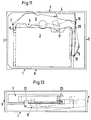
- Figure 10 is a partial plan view of the magnetic tape recorder, depicting the tape drive bridge in its running position with the fully loaded tape cassette.
- Figure 11 is a schematic partial plan view of the magnetic tape recorder, depicting the movement of the tape drive bridge from its standby position to its running position.
- Figure 12 is a side elevational view of the bridge inward leg reference area and leaf spring engaging the base plate of the tape cassette as the tape drive bridge reaches its running position.
- Figure 13 is a schematic side elevational view, depicting the movement of the outward leg of the tape drive bridge from its standby position to its running position.
- Figure 14 is a schematic side elevational view, depicting the pin and slots associated with the outward leg of the tape drive bridge, for bringing about the movement of the outward leg as depicted in Figure 13.
- Figure 15 is a side elevational, cross-sectional view, depicting activation of the lifting arm by the outward leg of the tape drive bridge for bringing the Y-shaped leaf spring up into engagement with the tape cassette baseplate beneath the reference areas on the outward leg of the bridge.
- Figure 16 is a top plan view of the interior of the magnetic recorder housing showing a manual cassette eject mechanism for moving the tape drive bridge and cassette unloader drive train.
- Figure 17 is a partial top plan view showing that portion of the manual cassette eject mechanism for moving the tape drive bridge.
- Figure 18 is a partial top plan view showing that portion of the manual cassette eject mechanism for operating the drive train of the cassette unloader.
- the preferred embodiment of the magnetic tape recorder has a rectangular housing 1. At the opposed longitudinal ends of the recorder housing 1 are an outward side wall O and an inward side wall I.
- the opposed lateral side walls of the recorder housing will be identified as the front side wall F and the rear, or back, side wall R.
- the outwardly facing side wall O is formed with an insertion slot 2 for receiving a magnetic tape cartridge or cassette 3.
- the cassette 3 is inserted manually into the housing opening 2 endwise in a longitudinal direction. When the cassette 3 has been fully loaded in the recorder housing and is engaged for read/write operation, the cassette will be disposed as illustrated with the dash line depiction.
- the magnetic tape cassette is preferably of the type which meets standard specifications, such as that depicted in U.S. Patent 3,976,262 or U.S. Patent 4,573,091.
- a tape drive bridge 4 made of stiff material and having a generally U-shape configuration.
- the bridge 4 is suspended at one point in a ball joint 5, around which point the bridge can rotate in all three axes.
- the ball joint 5 is situated within the base 6 of the bridge between an inward side leg 7 and an outward side leg 8.
- the bridge is suspended with pins sliding in grooves, the grooves defining the pitch and roll rotation of the bridge as a function of the yaw rotation.
- the bridge base 6 carries a magnetic head 11 for performing the read/write operation on the cassette tape and an associated magnetic head positioning assembly 12 for shifting the magnetic head read/write gap between tracks and otherwise properly disposing the magnetic head along a tape track.
- a tape capstan drive train 13 for interconnecting the spur gear of a rotary electric motor 14 (also disposed on the bridge 4) to a driven tape transport wheel contained in the tape cassette 3, when the bridge 4 is in its running position. In its standby position, the electric motor's spur gear is drivingly connected to a wheel 35, discussed below.
- the tape drive bridge 4 is in its standby position, whereby reference areas and other hard stop locating areas on the bridge, as well as the magnetic head 11, are out of the way of the path of movement of the tape cassette 3 when the cassette is loaded or unloaded in the recorder housing 1.
- the loading and unloading of the cassette in the recorder housing is conducted over a housing frame plate P disposed between the rear side wall R and the bridge 4.
- a first leaf spring arrangement 16 is attached to the bridge beneath the leg 7 and formed with an outwardly and upwardly extending spring arm 17 generally underlying the reference area 15.
- the vertical extension of the spring arm 17 is accommodated in the recorder housing by a opening 18 formed in the housing frame plate P.
- the spring arm 17 of the leaf spring 16 serves to force the inward end of the cassette base plate up against the reference area 15 on the bridge.
- a second leaf spring 19 Disposed along the rear side wall R of the recorder housing is a second leaf spring 19.
- the spring 19 will apply a supporting force against the rear side of the cassette 3 adjacent its outward end, when the cassette has been fully loaded into the recorder housing and the bridge has been moved from its standby position as shown in Figure 2 to its running position.
- the grasping of the spring arm 17 of the cassette base plate against the bridge reference area 15, when the bridge is moved into its running position will cause a slight skewing of the cassette in the recorder housing, thus pressing the rear side of the cassette adjacent its outward end against the leaf spring 19.
- this bridge leg 8 of the bridge there are formed along this bridge leg second and third reference areas, 20 and 21, respectively, which will also act to clamp down onto the base plate of the cassette, along the outward end of the cassette, when the bridge is moved into its running position.
- a leaf spring 22 having a generally Y-shape configuration.
- the respective free ends of the Y arms are provided with upwardly extending engagement knobs or surfaces 23 and 24.
- These engagement knobs 23 and 24 of the third spring 22 will serve to force the base plate surfaces of the cassette up against the reference areas 20 and 21, respectively, when the bridge 4 is moved into its running position.
- the engagement knob 24 of the spring 22 is thus able to protrude through an opening formed in the frame plate P.
- the apex of the Y arms on the spring 22 is formed with a lift surface 25, as viewed through an opening in the frame plate P.
- a pivotable lifting arm device 26 will engage the lift surface 25 and serve to raise the spring arms and their respective engagement knobs 23 and 24 up against the cassette base plate, when the bridge 4 is moved into its running position.
- This activation of the lifting arm 25 is brought about by a drive surface formed on the leg 8 of the bridge contacting and moving the lifting arm 26, when the bridge is moved into its running position.
- the three axes movement of the bridge 4 and the outward side leg 8 is controlled by the pins sliding in grooves at 9 and 10.
- an electric motor-driven crank mechanism For bringing about the movement of the bridge between its standby and running positions, an electric motor-driven crank mechanism is utilized.
- a wing section 27 of the bridge containing an appropriately curved groove 28 which receives therein a pin 29.
- a separate rotary electric motor 30 Adjacent the outward end of the recorder housing 1 and proximate the outward leg 8 of the bridge 4 is a separate rotary electric motor 30.
- the function of this electric motor 30 is to drive the movement of the bridge 4 between its standby and running positions.
- the electric motor is connected through driven gear wheels to a crank 31.
- the crank 31 is fitted at its outer free end with the pin 29 that fits into the slot 28 formed in the bridge.
- the pin 29 is rotated counterclockwise, as viewed in Figure 2, approximately 180°, the bridge 4 is rotated from its standby position to its running position. Rotating the pin 29 the other way, via the electric motor 30, puts the bridge back in standby position.
- Figure 3 depicts the mechanical system by which the tape cassette 3 is loaded and unloaded in the recorder housing 1 and which also serves to open the hinged dust cover on the front side of the cassette to expose the tape therein for operative engagement by the magnetic head 11 when the bridge 4 is disposed in its running position.
- the mechanical arrangement shown in Figure 3 is situated on the underside of the top cover of the recorder housing so as to overlie the cassette 3 in the recorder housing.
- the tape drive motor 14 is activated, in the appropriate direction, to operate drive train wheels 13 disposed on the bridge 4 a cassette transport drive wheel 35, supported for rotation adjacent the front side edge of the recorder housing.
- the drive wheel 35 looses its driving connection with the gear train wheels 13 disposed on the bridge 4 when the bridge is rotated from its standby to running position.
- the drive wheel 35 acts through a series of reduction gears to operate a toothed rack 36, disposed for longitudinal back and forth movement within the recorder housing.
- a pivotable gripper 37 which extends downwardly from the rack for disposition facing the inward end of the cassette 3 being handled by the recorder housing.
- the downward vertical extension of the gripper 37 is accommodated by a longitudinally extending opening 38 (see Figure 2) formed in the frame plate P.
- the rack 36 is disposed in its fully outward extended position, with the gripper 37 awaiting the insertion of a cassette 3 partway into the recorder housing 1 so that the gripper 37 can then grasp the inward side edge of the cassette and pull the cassette further inward to the fully loaded position in try recorder housing upon movement of the rack 36 in the inward, loading direction.
- the gripper 37 has a main body 39 which is that portion of the gripper extending downward into the recorder housing for handling transport of the cassette 3 during automatic loading and unloading of the cassette.
- the body 39 has upper and lower jaws 40 and 41, respectively, defining therebetween a mouth 42 in which the inwardly facing extension of the cassette base plate is received.
- the upper end of the body 39 is supported on a hinge pin 43 which extends laterally across the rack 36 at the inward facing end of the rack.
- Extending laterally to one side of the gripper main body 39 is an integrally formed cam follower surface 44, the movement of which thus causes the gripper main body 39 to rotate about the hinge pin 43.
- a support bracket 45 Fixed to the rack is a support bracket 45 on which a leaf spring 46 is mounted and which is connected to the main body 39 of the gripper to provide a biasing force on the gripper body about the hinge pin 43, such that the gripper body 39 will rotate in the counterclockwise direction about the hinge pin, as viewed in Figures 4 and 5.
- Cam surfaces 47 and 48 are formed on the gear rack track at opposed ends of the travel path of the gripper 37.
- the outward-most end of the gear rack 36 is formed with a laterally extending cam surface 50. Disposed in the line of movement of the cam surface 50 is one end of the linkage mechanism 51 which serves to open the hinged dust cover on the cassette 3. As further shown in Figure 10, after the hinged dust cover of the cassette has been partially opened by the operation of the linkage mechanism 51, further inward movement of the cassette in the recorder housing causes the dust cover to ride up into a prescribed opening formed within the bridge 4 so that the dust cover is moved out of the way of the magnetic head engagement with the tape in the cassette.
- the linkage mechanism 51 is constructed and operates as follows.
- the mechanism 51 is generally in the form of a lever arm 52 which pivots about a hinge pin 53.
- the arm 52 is biased in a clockwise direction, as viewed in Figure 3, by the resilient force of a generally curved spring arm 54.
- the clockwise rotation of the arm 52 about the hinge pin 53 is limited by a fixed stop 55 against which a wing surface 56 of the arm abuts.
- Figure 3 shows the linkage mechanism 51 for opening the dust cover of the cassette in its standby position.
- the dust cover of the cassette opens still further, following the contours of the bridge opening 59, such that the tape of the cassette is exposed for operative engagement by the magnetic head 11, when the bridge 4 is brought to its running position.
- the tape drive bridge 4 With the tape cassette thus fully loaded in the recorder housing, the tape drive bridge 4 is moved from its standby position to its running position in which the tape is operatively engaged by the magnetic head 11. In its running position, the bridge 4 creates a stable and stiff locking connection between the cassette and the magnetic head, as shown in Figure 10.
- the bridge 4 locks in the cassette at the three reference areas 15, 20, and 21 formed on the inward side leg 7 and the outward side leg 8, respectively. In the lateral direction, this grasping of the cassette at the bridge reference areas holds the cassette against hard stop surfaces formed on the bridge, such as may be formed at area 60, as shown in Figure 10.
- the manner in which the bridge 4 came to lock together with the cassette 3 at the three reference areas as the bridge moved from its standby position as shown in Figure 2 to its running position as shown in Figure 10 is further described with reference to the remaining figures.
- the pin and groove arrangement 9 comprises a pin member 61 which extends integrally and outwardly from the bridge leg adjacent the bridge reference area 21.
- This pin 61 tracks its movement along a groove path 62 formed as a cut-away in the framework of the recorder housing.
- the reference area 21 on the bridge proceeds from its standby position to its running position by initially traveling upward to above the lateral plane of the outwardly facing cassette base plate, and then across and over the base plate until, as the bridge reaches its running position, the reference area 21 clamps down onto the cassette base plate in the direction of the arrow shown in Figure 14.
- a pin 63 is fixed in the recorder housing framework and a groove 64 is cut in the bridge adjacent the third bridge reference area 20 for tracking the movement of the bridge over the pin 63 as the bridge moves from its standby position to its running position.
- the pin and groove arrangement 10 causes the reference area 20 on the bridge to initially proceed upwardly above the lateral plane of the cassette base plate, and then over and across to the base plate whereupon, when the bridge reaches its running position, the reference area 20 clamps down onto the cassette base plate.
- the reverse rotation of the bridge 4 from its running position to its standby position, such that the tape cassette can be unloaded from the recorder housing is also controlled by the pin and groove arrangements 9 and 10.
- the bridge is rotated in the yaw axis back from its running position as depicted in Figure 10 to its standby position as depicted in Figure 2, via the operation of the crank arm 31.
- the magnetic head 11 is withdrawn from the cassette tape, and the grooves 62 and 64 twist the bridge leg 8 downwardly so that the second and third bridge reference areas 20 and 21 are then disposed underneath the base plate of the cassette and the outwardly facing end of the cassette is cleared for unloading.
- the tape cassette is locked in place with the bridge at the three reference areas formed on the bridge, namely 15, 20, and 21, and there is no movement between the bridge reference areas and the associated cassette base plate surfaces on which the reference areas clamp, when the forces of the leaf springs, namely 17 and 22, are applied.
- Figures 16-18 pertain to a manually operated mechanism 70 for unloading a stranded cassette C from the recorder housing 1 in case the electrical system of the recorder does not work and the electric motors are not operating.
- the manual eject mechanism 70 enables the operator to manipulate rotation of the crank 31 to rotate the bridge 4 (shown schematically in Figure 16) from its running position engaging the cassette C to its standby position back out of the way of the cassette's path of movement out of the housing 1.
- the mechanism 70 also allows the operator to manipulate the gear train which is connected to the gear rack 36 such that the gripper 37 is conducted outwardly in its unloading stroke, ejecting the cassette outward through the slot 2 formed in the recorder housing for retrieval by the operator.
- the mechanism 70 includes an eject button 71 which extends outwardly from the face of the recorder housing and which is journaled at its inward end for pivotal movement about a vertical shaft 72.
- the button 71 is a laterally extending body having a rear side facing end A and a front side facing end B, on opposed sides of said pivot shaft 72.
- the eject button 71 has two operational modes. It first operates as an electrical switch to restart the electric motors. In this mode, the operator pushes inward on side A of the eject button 71 to engage a restart button 73 positioned slightly inward from the eject button within the recorder housing.
- restart button 73 If activation of the restart button 73 fails to work the electrical system of the recorder, then the operator may further work the eject button 71 in a manual cassette eject mode, as shown in Figures 18 and 19.
- the first step of the manual cassette eject mode is for the operator to push the side A of the eject button 71 further inward for rotation about the pivot shaft 72, beyond the point where side A of the button is flush with the housing wall and beyond the electrical switching position.
- This movement of the button 71 is shown in Figure 18, and may be accomplished with a tool, such as a pen or pencil 74.
- a tool such as a pen or pencil 74.
- Connected on the interior facing surface of the button 71, on side A of the button is an inwardly extending ratchet arm 75, the free end of which is received between the gear teeth of a drive wheel 76 keyed for rotation on a shaft of the gear train which forms the driving connection between the electric motor 30 and the crank 31.
- the gear wheel 76 is in driving connection with a further gear 77 keyed for rotation on the shaft which turns the crank 31.
- a further gear 77 keyed for rotation on the shaft which turns the crank 31.
- the ratchet arm 75 is slightly deformed in its inward extension between the button 71 and the teeth of the gear wheel 76, so that the ratchet arm 75 is sufficiently resilient to merely become straightened during the rotational movement of the button 71 commencing at side B and does not then ratchet the gear wheel 76 in the opposite direction from that discussed above with respect to the Figure 17.
- the inward facing surface of the eject button 71, at side B is formed with an inwardly elongated arm 78 having an interior free end for engaging against the teeth of a driving gear 79.
- Gear 79 is mounted for rotation on the top wall of the recorder housing, as shown in Figures 3 and 15.
- the gear 79 is keyed for rotation about the same vertically extending shaft as the driven wheel 35, which is part of the gear train leading to the gear rack 36, such that rotation of the gear 79 serves to bring about longitudinal movement of the gear rack 36 and gripper 37.
- the inwardly elongated arm 79 is supported and guided for generally linear longitudinal movement in the recorder housing by a guide bracket 80 formed on the interior of the front side wall of the recorder housing.
- the elongated arm 78 is formed with recessed or cut-away areas 81 and 82 adjacent the eject button and the free end of the arm, respectively, and on opposite sides of the guide bracket 80 to provide bending joints along the extension of the elongated arm 78.
- an appropriate resilience is provided to the elongated arm 78 such that each portion thereof extending further inward from each cut-away area 81 and 82 may bend relative to the next adjacent outward portion of the arm 78.
Landscapes
- Automatic Tape Cassette Changers (AREA)
Description
Claims (18)
- A magnetic tape recorder for receiving an endwise loaded rectangular tape cassette (3) having a pair of opposed sides and a pair of opposed ends which are shorter than said sides, said tape cassette (3) enclosing a length of magnetic tape and having an opening in one of said sides proximate one of said ends for providing access to said length of tape, and which has a magnetic head (11) for reading/writing data on said magnetic tape when said magnetic head (11) is in operative engagement with said magnetic tape and a capstan drive train (13) for activating a tape drive in said tape cassette (3) to conduct said length of magnetic tape across said magnetic head (11),
characterized in that
said magnetic head (11) and said capstan drive train (13) are carried by a bridge (4), said bridge being rotatable in all three axes from a lowered standby position, where said bridge (4) is spaced from said tape cassette (3), and a raised running position, where said bridge (4) engages said tape cassette (3), connects said capstan drive train (13) between an electric motor (14) and said tape drive, and operatively engages said magnetic head (11) with said magnetic tape. - The magnetic tape recorder of claim 1, wherein said bridge (4) clamps onto said cassette (3) at three discrete reference areas (15, 20, 21) formed on said bridge (4), when said bridge is in its running position.
- The magnetic recorder of claims 1 or 2, wherein an electric motor-driven crank (31) is connected to said bridge (4) to move said bridge (4) between its standby position and its running position, and the path of said movement of said bridge (4) is controlled by at least one pin-and-groove connection (28, 29).
- The magnetic recorder of claim 2, wherein said bridge (4) is generally of a U-shape, said reference areas (15, 20, 21) being disposed on the legs (7, 8) of said U and said magnetic head (11) and said capstan drive train (13) being disposed on the base of said U.
- The magnetic recorder of claims 2 or 4, wherein only one reference area (15) clamps onto said cassette (3) at one end of said cassette and only two reference areas (20, 21) clamp onto said cassette (3) at the other end of said cassette.
- The magnetic recorder of claim 2, wherein springs (16, 22) underlie said reference areas (15, 20, 21) of said bridge (4), and said cassette (3) is clamped between said reference areas (15, 20, 21) and said springs (16, 22) when said bridge (4) is in its running position.
- The magnetic recorder of claim 5, wherein springs (16, 22) underlie said reference areas (15, 20, 21) of said bridge (4), and said cassette (3) is clamped between said reference areas (15, 20, 21) and said springs (16, 22) when said bridge (4) is in its running position.
- The magnetic recorder of claim 1, further including a drive wheel (35) mounted on said bridge (4) for operatively connecting said electric motor (14) with a means for automatically loading and unloading said tape cassette in said magnetic recorder when said bridge (4) is in its standby position, said drive wheel (35) being disconnected from said electric motor (14) when said bridge (4) moves from its standby position to its running position.
- A magnetic tape recorder according to one of the preceding claims, wherein said tape cassette (3) is locked by said bridge (4), when said bridge (4) engages said tape cassette (3).
- A magnetic tape recorder according to claim 9, wherein said three reference areas (15, 20, 21) clamp onto the longitudinal ends of said tape cassette (3).
- A magnetic tape recorder according to one of the preceding claims, wherein said bridge (4) is movable in all three axes about a ball joint (5) from a standby position, away from said tape cassette (3), to a running position, wherein said reference areas (15, 20, 21) clamp onto said tape cassette (3).
- A magnetic tape recorder according to claim 11, wherein one said spring (16) is connected on said bridge (4) and disposed beneath one said reference area (15), said one spring (16) pulling said cassette (3) into engagement with said one reference area (15) when said bridge (4) moves from its standby position to its running position.
- A magnetic tape recorder according to claim 11, wherein one said spring (16, 22) is pushed into engagement with said cassette (3) across from one said reference area (15, 20, 21) when said bridge (4) moves to its running position, by a member mounted on said bridge (4).
- A method for locking a magnetic tape cassette, of rectangular configuration, loaded in a magnetic tape recorder, into operational engagement with a tape capstan drive train (13) and a magnetic head (11),
characterized by
engaging said tape cassette by a bridge (4), said bridge carrying said magnetic head (11) and said capstan drive train (13), and being rotatable in all three axes from a lowered standby position, where said bridge (4) is spaced from said tape cassette (3), and a raised running position, where said bridge (4) engages said tape cassette (3), connects said capstan drive train (13) between an electric motor (14) and a tape drive, and operatively engages said magnetic head (11) with said magnetic tape. - The method of claim 14, wherein said engaging is performed at three discrete location areas on the surface of said tape cassette (3); andsaid method further comprisingclamping said tape cassette (3) against a spring tension at each of said discrete location areas.
- The method of claim 15, wherein said three location areas are on the opposed longitudinal ends of said tape cassette (3).
- The method of claims 15 or 16, further comprising:
skewing said tape cassette (3) off its longitudinal axis as loaded in said magnetic tape recorder, when said clamping step is performed. - The method of claim 15, wherein said spring tension is provided by three discrete spring members (16, 22) acting on said tape cassette (3) proximate said three discrete location areas.
Applications Claiming Priority (2)
| Application Number | Priority Date | Filing Date | Title |
|---|---|---|---|
| US88748 | 1987-08-24 | ||
| US08/088,748 US5440435A (en) | 1993-07-08 | 1993-07-08 | Cartridge manipulation and reference system for magnetic tape recorder |
Publications (3)
| Publication Number | Publication Date |
|---|---|
| EP0633568A2 EP0633568A2 (en) | 1995-01-11 |
| EP0633568A3 EP0633568A3 (en) | 1995-02-08 |
| EP0633568B1 true EP0633568B1 (en) | 1998-05-27 |
Family
ID=22213221
Family Applications (1)
| Application Number | Title | Priority Date | Filing Date |
|---|---|---|---|
| EP93118134A Expired - Lifetime EP0633568B1 (en) | 1993-07-08 | 1993-11-09 | Cartridge manipulation and reference system for magnetic tape recorder |
Country Status (4)
| Country | Link |
|---|---|
| US (2) | US5440435A (en) |
| EP (1) | EP0633568B1 (en) |
| JP (1) | JP2633805B2 (en) |
| DE (1) | DE69318830T2 (en) |
Families Citing this family (19)
| Publication number | Priority date | Publication date | Assignee | Title |
|---|---|---|---|---|
| US5558291A (en) * | 1994-05-16 | 1996-09-24 | Imation Corp. | Drive for handling multiple size information storage media cartridges and cartridges therefor |
| JP3584118B2 (en) * | 1995-04-21 | 2004-11-04 | ヒューレット・パッカード・カンパニー | Door opening device for tape cartridge |
| US5956199A (en) * | 1995-05-26 | 1999-09-21 | International Business Machines Corporation | Head to tape alignment without tape guide |
| US5657181A (en) * | 1995-09-21 | 1997-08-12 | Iomega Corporation | Opening lever for magnetic tape cartridge door |
| US5777830A (en) * | 1996-10-09 | 1998-07-07 | Gigatek Memory Systems | Belt-driven tape cartridge having increased tape capacity |
| US5883755A (en) * | 1996-10-21 | 1999-03-16 | U.S. Philips Corporation | Apparatus for storage and/or reproduction of information on/from an information carrier |
| EP0870302A1 (en) * | 1996-10-21 | 1998-10-14 | OnStream, Inc. | Apparatus for recording and/or reproducing information on/from an information carrier |
| US5870246A (en) * | 1997-04-16 | 1999-02-09 | Tandberg Data Asa | Reference bridge for supporting a tape cartridge within a tape drive |
| JPH1139746A (en) * | 1997-07-17 | 1999-02-12 | Alps Electric Co Ltd | Magnetic recording / reproducing device |
| JP3570533B2 (en) | 1998-01-28 | 2004-09-29 | アルプス電気株式会社 | Magnetic recording / reproducing device |
| JPH11224449A (en) | 1998-02-05 | 1999-08-17 | Alps Electric Co Ltd | Magnetic recording / reproducing device |
| JPH11238272A (en) * | 1998-02-23 | 1999-08-31 | Alps Electric Co Ltd | Magnetic recording / reproducing device |
| KR20040024878A (en) * | 2001-08-07 | 2004-03-22 | 세그웨이 시스템즈, 엘엘씨 | Tape cartridge docking apparatus for read/write recording assemblies and method therefor |
| US8573578B1 (en) | 2006-09-01 | 2013-11-05 | Chick Workholding Solutions, Inc. | Workholding apparatus |
| US8454004B1 (en) * | 2006-09-01 | 2013-06-04 | Chick Workholding Solutions, Inc. | Workholding apparatus having a movable jaw member |
| US8336867B1 (en) | 2006-09-01 | 2012-12-25 | Chick Workholding Solutions, Inc. | Workholding apparatus having a detachable jaw plate |
| US9227303B1 (en) * | 2006-09-01 | 2016-01-05 | Chick Workholding Solutions, Inc. | Workholding apparatus |
| EP2478840A1 (en) * | 2011-01-19 | 2012-07-25 | Roche Diagnostics GmbH | Medical hand-held device |
| US9352451B1 (en) | 2013-05-02 | 2016-05-31 | Chick Workholding Solutions, Inc. | Workholding apparatus |
Family Cites Families (35)
| Publication number | Priority date | Publication date | Assignee | Title |
|---|---|---|---|---|
| AT267214B (en) * | 1966-11-03 | 1968-12-27 | Philips Nv | Recording and / or reproducing device |
| US3689077A (en) * | 1968-09-26 | 1972-09-05 | Victor Company Of Japan | Operation device for cassette type tape recorder |
| US3610497A (en) * | 1968-11-27 | 1971-10-05 | Itsuki Ban | Tape cartridge latching apparatus |
| US3758119A (en) * | 1971-07-01 | 1973-09-11 | Motorola Inc | Automatic eject mechanism for cassette tape player |
| JPS5538825B2 (en) * | 1972-01-31 | 1980-10-07 | ||
| US3811625A (en) * | 1972-03-16 | 1974-05-21 | Cybrix Corp | Magnetic tape cassette changer |
| US3976262A (en) * | 1973-12-17 | 1976-08-24 | C. J. Kennedy Company | Magnetic tape cartridge recorder having releasable cartridge catch arrangement and non-resonant type drive |
| IT1062570B (en) * | 1976-02-25 | 1984-10-20 | Deneb Sa | DEVICE FOR GRIPPING AND TRANSLATION OF A CASSETTE TO THE TURNTABLE OR BELT RECORDERS AND SIMILAR |
| DE3315822A1 (en) * | 1982-06-02 | 1983-12-08 | Philips Patentverwaltung Gmbh, 2000 Hamburg | CONTROL DEVICE FOR THE DRIVE OF A MAGNETIC TAPE CASSETTE DEVICE |
| US4573091A (en) * | 1982-11-15 | 1986-02-25 | Cipher Data Products, Inc. | Cartridge tape drive |
| DE3317720A1 (en) * | 1982-11-29 | 1984-11-22 | Tandberg Data A/S, Oslo | MAGNETIC TAPE DEVICE |
| EP0125765A3 (en) * | 1983-05-13 | 1985-08-28 | Cipher Data Products, Inc. | Cartridge alignment mechanism for tape drive |
| US4636890A (en) * | 1983-05-16 | 1987-01-13 | Tandberg Data A/S | Magnetic tape recorder |
| US4556923A (en) * | 1983-11-28 | 1985-12-03 | Data Electronics, Inc. | Tape cartridge drive with cartridge door opening mechanism |
| JPS60163572U (en) * | 1984-04-03 | 1985-10-30 | ソニー株式会社 | tape cassette |
| US4608615A (en) * | 1984-04-30 | 1986-08-26 | Mark Zeavin | Half height data cartridge tape drive |
| US4673995A (en) * | 1984-07-06 | 1987-06-16 | Kennedy Company | Cartridge tape drive with friction roller to open cartridge door |
| US4796120A (en) * | 1986-03-17 | 1989-01-03 | Kabushiki Kaisha Sankyo Seiki Keisakusho | Magnetic tape drive machine |
| JPS62239362A (en) * | 1986-04-09 | 1987-10-20 | Matsushita Electric Ind Co Ltd | Cassette loading device |
| US4755900A (en) * | 1986-07-07 | 1988-07-05 | Minnesota Mining And Manufacturing Company | Tape cartridge drive with tape biasing arm to allow head movement normal to tape path |
| US4866552A (en) * | 1986-10-27 | 1989-09-12 | Arnitsu Corporation | Magnetic tape drive with improved cartridge insertion and withdrawal mechanism |
| DE3714702A1 (en) * | 1987-05-02 | 1988-11-17 | Philips Patentverwaltung | DEVICE FOR ADJUSTING A FUNCTIONAL PART IN AN ELECTRICAL DEVICE |
| EP0293033A3 (en) * | 1987-05-25 | 1989-10-18 | Philips Patentverwaltung GmbH | Magnetic tape cassette apparatus |
| US5105320A (en) * | 1988-03-15 | 1992-04-14 | Clarion Co., Ltd. | Operation mode switching and loading-eject mechanism for a tape player |
| US5109308A (en) * | 1989-04-25 | 1992-04-28 | Archive Corporation | Stationary head tape drive with a movable door opening mechanism |
| JP2961747B2 (en) * | 1989-04-27 | 1999-10-12 | ソニー株式会社 | Recording and / or playback device |
| US5025334A (en) * | 1989-09-12 | 1991-06-18 | Cipher Data Products, Inc. | Auto-loading transport for tape cartridge with tape access door and belt capstan roller |
| US5204792A (en) * | 1989-11-09 | 1993-04-20 | Wangtek, Inc. | Cartridge tape drive |
| JPH0661140B2 (en) * | 1990-01-31 | 1994-08-10 | タナシン電機株式会社 | Tape slack eliminating device for tape recorders |
| JPH041942A (en) * | 1990-04-18 | 1992-01-07 | Sumitomo Electric Ind Ltd | Reflected light measurement element |
| AU652390B2 (en) * | 1990-11-30 | 1994-08-25 | Conner Peripherals, Inc | Narrow profile data storage cartridge tape drive of small overall size |
| JPH052802A (en) * | 1991-06-26 | 1993-01-08 | Sony Corp | Cassette transport machine |
| CA2070973A1 (en) * | 1992-01-31 | 1993-08-01 | William R. Miller | Reduced height minicartridge tape drive for three and one-half inch form factor |
| US5323280A (en) * | 1992-02-19 | 1994-06-21 | Tandberg Data A/S | Three point reference system for a cartridge in a tape drive |
| US5373406A (en) * | 1993-08-12 | 1994-12-13 | Tandberg Data A/S | Auto load/eject system for tape cassette |
-
1993
- 1993-07-08 US US08/088,748 patent/US5440435A/en not_active Expired - Fee Related
- 1993-11-09 EP EP93118134A patent/EP0633568B1/en not_active Expired - Lifetime
- 1993-11-09 DE DE69318830T patent/DE69318830T2/en not_active Expired - Fee Related
-
1994
- 1994-04-06 JP JP6068561A patent/JP2633805B2/en not_active Expired - Lifetime
- 1994-12-29 US US08/365,826 patent/US5629816A/en not_active Expired - Fee Related
Also Published As
| Publication number | Publication date |
|---|---|
| EP0633568A3 (en) | 1995-02-08 |
| JP2633805B2 (en) | 1997-07-23 |
| US5440435A (en) | 1995-08-08 |
| EP0633568A2 (en) | 1995-01-11 |
| DE69318830D1 (en) | 1998-07-02 |
| US5629816A (en) | 1997-05-13 |
| JPH07110981A (en) | 1995-04-25 |
| DE69318830T2 (en) | 1998-09-24 |
Similar Documents
| Publication | Publication Date | Title |
|---|---|---|
| US5440435A (en) | Cartridge manipulation and reference system for magnetic tape recorder | |
| US4807067A (en) | Cartridge tape drive | |
| US4559571A (en) | Tape cartridge drive with movable read/write head | |
| JPH07130061A (en) | Data carrier loader data carrier load and exchange belt system | |
| US4752844A (en) | Tape cassette loading device in a magnetic tape recorder-reproducer apparatus | |
| JPS61180958A (en) | Cassette loading device | |
| US4755900A (en) | Tape cartridge drive with tape biasing arm to allow head movement normal to tape path | |
| JPH1125548A (en) | Video cassette recorder | |
| JPH061584B2 (en) | Magnetic recording / reproducing device | |
| GB2189925A (en) | Cassette tape player | |
| JPS6113299B2 (en) | ||
| JPH01146157A (en) | Cartridge magnetic tape operation device | |
| US3800320A (en) | Temporary stop device for cartridge tape player-recorder | |
| JP2578625B2 (en) | Cassette mounting device | |
| US6122137A (en) | Loading mechanism for a recording and reproducing apparatus wherein a switch mechanism and the loading mechanism are a single unit | |
| JPS62248158A (en) | Cassette tape mounting device | |
| JP2737167B2 (en) | Cassette loading device | |
| JP2525350B2 (en) | Recording or playback device | |
| JPH06139667A (en) | Cassette loading mechanism | |
| JPH0237158Y2 (en) | ||
| JPS5914886Y2 (en) | Cassette storage door opening/closing mechanism | |
| JP2984089B2 (en) | Information recording medium transport mechanism | |
| JPH0721642A (en) | Tape cassette loading device | |
| JPH04268248A (en) | Disk cartridge carrying device | |
| JPH05314625A (en) | Cartridge carrying mechanism |
Legal Events
| Date | Code | Title | Description |
|---|---|---|---|
| PUAI | Public reference made under article 153(3) epc to a published international application that has entered the european phase |
Free format text: ORIGINAL CODE: 0009012 |
|
| PUAL | Search report despatched |
Free format text: ORIGINAL CODE: 0009013 |
|
| AK | Designated contracting states |
Kind code of ref document: A2 Designated state(s): DE FR GB |
|
| AK | Designated contracting states |
Kind code of ref document: A3 Designated state(s): DE FR GB |
|
| 17P | Request for examination filed |
Effective date: 19950711 |
|
| 17Q | First examination report despatched |
Effective date: 19960725 |
|
| GRAG | Despatch of communication of intention to grant |
Free format text: ORIGINAL CODE: EPIDOS AGRA |
|
| GRAG | Despatch of communication of intention to grant |
Free format text: ORIGINAL CODE: EPIDOS AGRA |
|
| GRAH | Despatch of communication of intention to grant a patent |
Free format text: ORIGINAL CODE: EPIDOS IGRA |
|
| GRAH | Despatch of communication of intention to grant a patent |
Free format text: ORIGINAL CODE: EPIDOS IGRA |
|
| RAP1 | Party data changed (applicant data changed or rights of an application transferred) |
Owner name: TANDBERG DATA ASA |
|
| GRAA | (expected) grant |
Free format text: ORIGINAL CODE: 0009210 |
|
| AK | Designated contracting states |
Kind code of ref document: B1 Designated state(s): DE FR GB |
|
| PG25 | Lapsed in a contracting state [announced via postgrant information from national office to epo] |
Ref country code: FR Free format text: LAPSE BECAUSE OF FAILURE TO SUBMIT A TRANSLATION OF THE DESCRIPTION OR TO PAY THE FEE WITHIN THE PRESCRIBED TIME-LIMIT Effective date: 19980527 |
|
| REF | Corresponds to: |
Ref document number: 69318830 Country of ref document: DE Date of ref document: 19980702 |
|
| EN | Fr: translation not filed | ||
| PLBE | No opposition filed within time limit |
Free format text: ORIGINAL CODE: 0009261 |
|
| STAA | Information on the status of an ep patent application or granted ep patent |
Free format text: STATUS: NO OPPOSITION FILED WITHIN TIME LIMIT |
|
| PGFP | Annual fee paid to national office [announced via postgrant information from national office to epo] |
Ref country code: FR Payment date: 19990525 Year of fee payment: 6 |
|
| 26N | No opposition filed | ||
| PGFP | Annual fee paid to national office [announced via postgrant information from national office to epo] |
Ref country code: GB Payment date: 20000405 Year of fee payment: 7 |
|
| PG25 | Lapsed in a contracting state [announced via postgrant information from national office to epo] |
Ref country code: GB Free format text: LAPSE BECAUSE OF NON-PAYMENT OF DUE FEES Effective date: 20001109 |
|
| PGFP | Annual fee paid to national office [announced via postgrant information from national office to epo] |
Ref country code: DE Payment date: 20001121 Year of fee payment: 8 |
|
| GBPC | Gb: european patent ceased through non-payment of renewal fee |
Effective date: 20001109 |
|
| PG25 | Lapsed in a contracting state [announced via postgrant information from national office to epo] |
Ref country code: DE Free format text: LAPSE BECAUSE OF NON-PAYMENT OF DUE FEES Effective date: 20020702 |