EP0633437B1 - Cryogenic liquid nitrogen production system and apparatus - Google Patents
Cryogenic liquid nitrogen production system and apparatus Download PDFInfo
- Publication number
- EP0633437B1 EP0633437B1 EP94110470A EP94110470A EP0633437B1 EP 0633437 B1 EP0633437 B1 EP 0633437B1 EP 94110470 A EP94110470 A EP 94110470A EP 94110470 A EP94110470 A EP 94110470A EP 0633437 B1 EP0633437 B1 EP 0633437B1
- Authority
- EP
- European Patent Office
- Prior art keywords
- nitrogen
- vapor
- column
- liquid
- stream
- Prior art date
- Legal status (The legal status is an assumption and is not a legal conclusion. Google has not performed a legal analysis and makes no representation as to the accuracy of the status listed.)
- Expired - Lifetime
Links
Images

Classifications
-
- F—MECHANICAL ENGINEERING; LIGHTING; HEATING; WEAPONS; BLASTING
- F25—REFRIGERATION OR COOLING; COMBINED HEATING AND REFRIGERATION SYSTEMS; HEAT PUMP SYSTEMS; MANUFACTURE OR STORAGE OF ICE; LIQUEFACTION SOLIDIFICATION OF GASES
- F25J—LIQUEFACTION, SOLIDIFICATION OR SEPARATION OF GASES OR GASEOUS OR LIQUEFIED GASEOUS MIXTURES BY PRESSURE AND COLD TREATMENT OR BY BRINGING THEM INTO THE SUPERCRITICAL STATE
- F25J3/00—Processes or apparatus for separating the constituents of gaseous or liquefied gaseous mixtures involving the use of liquefaction or solidification
- F25J3/02—Processes or apparatus for separating the constituents of gaseous or liquefied gaseous mixtures involving the use of liquefaction or solidification by rectification, i.e. by continuous interchange of heat and material between a vapour stream and a liquid stream
- F25J3/0228—Processes or apparatus for separating the constituents of gaseous or liquefied gaseous mixtures involving the use of liquefaction or solidification by rectification, i.e. by continuous interchange of heat and material between a vapour stream and a liquid stream characterised by the separated product stream
- F25J3/028—Processes or apparatus for separating the constituents of gaseous or liquefied gaseous mixtures involving the use of liquefaction or solidification by rectification, i.e. by continuous interchange of heat and material between a vapour stream and a liquid stream characterised by the separated product stream separation of noble gases
- F25J3/029—Processes or apparatus for separating the constituents of gaseous or liquefied gaseous mixtures involving the use of liquefaction or solidification by rectification, i.e. by continuous interchange of heat and material between a vapour stream and a liquid stream characterised by the separated product stream separation of noble gases of helium
-
- F—MECHANICAL ENGINEERING; LIGHTING; HEATING; WEAPONS; BLASTING
- F25—REFRIGERATION OR COOLING; COMBINED HEATING AND REFRIGERATION SYSTEMS; HEAT PUMP SYSTEMS; MANUFACTURE OR STORAGE OF ICE; LIQUEFACTION SOLIDIFICATION OF GASES
- F25J—LIQUEFACTION, SOLIDIFICATION OR SEPARATION OF GASES OR GASEOUS OR LIQUEFIED GASEOUS MIXTURES BY PRESSURE AND COLD TREATMENT OR BY BRINGING THEM INTO THE SUPERCRITICAL STATE
- F25J3/00—Processes or apparatus for separating the constituents of gaseous or liquefied gaseous mixtures involving the use of liquefaction or solidification
- F25J3/02—Processes or apparatus for separating the constituents of gaseous or liquefied gaseous mixtures involving the use of liquefaction or solidification by rectification, i.e. by continuous interchange of heat and material between a vapour stream and a liquid stream
- F25J3/0204—Processes or apparatus for separating the constituents of gaseous or liquefied gaseous mixtures involving the use of liquefaction or solidification by rectification, i.e. by continuous interchange of heat and material between a vapour stream and a liquid stream characterised by the feed stream
- F25J3/0209—Natural gas or substitute natural gas
-
- F—MECHANICAL ENGINEERING; LIGHTING; HEATING; WEAPONS; BLASTING
- F25—REFRIGERATION OR COOLING; COMBINED HEATING AND REFRIGERATION SYSTEMS; HEAT PUMP SYSTEMS; MANUFACTURE OR STORAGE OF ICE; LIQUEFACTION SOLIDIFICATION OF GASES
- F25J—LIQUEFACTION, SOLIDIFICATION OR SEPARATION OF GASES OR GASEOUS OR LIQUEFIED GASEOUS MIXTURES BY PRESSURE AND COLD TREATMENT OR BY BRINGING THEM INTO THE SUPERCRITICAL STATE
- F25J3/00—Processes or apparatus for separating the constituents of gaseous or liquefied gaseous mixtures involving the use of liquefaction or solidification
- F25J3/02—Processes or apparatus for separating the constituents of gaseous or liquefied gaseous mixtures involving the use of liquefaction or solidification by rectification, i.e. by continuous interchange of heat and material between a vapour stream and a liquid stream
- F25J3/0228—Processes or apparatus for separating the constituents of gaseous or liquefied gaseous mixtures involving the use of liquefaction or solidification by rectification, i.e. by continuous interchange of heat and material between a vapour stream and a liquid stream characterised by the separated product stream
- F25J3/0233—Processes or apparatus for separating the constituents of gaseous or liquefied gaseous mixtures involving the use of liquefaction or solidification by rectification, i.e. by continuous interchange of heat and material between a vapour stream and a liquid stream characterised by the separated product stream separation of CnHm with 1 carbon atom or more
-
- F—MECHANICAL ENGINEERING; LIGHTING; HEATING; WEAPONS; BLASTING
- F25—REFRIGERATION OR COOLING; COMBINED HEATING AND REFRIGERATION SYSTEMS; HEAT PUMP SYSTEMS; MANUFACTURE OR STORAGE OF ICE; LIQUEFACTION SOLIDIFICATION OF GASES
- F25J—LIQUEFACTION, SOLIDIFICATION OR SEPARATION OF GASES OR GASEOUS OR LIQUEFIED GASEOUS MIXTURES BY PRESSURE AND COLD TREATMENT OR BY BRINGING THEM INTO THE SUPERCRITICAL STATE
- F25J3/00—Processes or apparatus for separating the constituents of gaseous or liquefied gaseous mixtures involving the use of liquefaction or solidification
- F25J3/02—Processes or apparatus for separating the constituents of gaseous or liquefied gaseous mixtures involving the use of liquefaction or solidification by rectification, i.e. by continuous interchange of heat and material between a vapour stream and a liquid stream
- F25J3/0228—Processes or apparatus for separating the constituents of gaseous or liquefied gaseous mixtures involving the use of liquefaction or solidification by rectification, i.e. by continuous interchange of heat and material between a vapour stream and a liquid stream characterised by the separated product stream
- F25J3/0257—Processes or apparatus for separating the constituents of gaseous or liquefied gaseous mixtures involving the use of liquefaction or solidification by rectification, i.e. by continuous interchange of heat and material between a vapour stream and a liquid stream characterised by the separated product stream separation of nitrogen
-
- F—MECHANICAL ENGINEERING; LIGHTING; HEATING; WEAPONS; BLASTING
- F25—REFRIGERATION OR COOLING; COMBINED HEATING AND REFRIGERATION SYSTEMS; HEAT PUMP SYSTEMS; MANUFACTURE OR STORAGE OF ICE; LIQUEFACTION SOLIDIFICATION OF GASES
- F25J—LIQUEFACTION, SOLIDIFICATION OR SEPARATION OF GASES OR GASEOUS OR LIQUEFIED GASEOUS MIXTURES BY PRESSURE AND COLD TREATMENT OR BY BRINGING THEM INTO THE SUPERCRITICAL STATE
- F25J2200/00—Processes or apparatus using separation by rectification
- F25J2200/02—Processes or apparatus using separation by rectification in a single pressure main column system
-
- F—MECHANICAL ENGINEERING; LIGHTING; HEATING; WEAPONS; BLASTING
- F25—REFRIGERATION OR COOLING; COMBINED HEATING AND REFRIGERATION SYSTEMS; HEAT PUMP SYSTEMS; MANUFACTURE OR STORAGE OF ICE; LIQUEFACTION SOLIDIFICATION OF GASES
- F25J—LIQUEFACTION, SOLIDIFICATION OR SEPARATION OF GASES OR GASEOUS OR LIQUEFIED GASEOUS MIXTURES BY PRESSURE AND COLD TREATMENT OR BY BRINGING THEM INTO THE SUPERCRITICAL STATE
- F25J2200/00—Processes or apparatus using separation by rectification
- F25J2200/70—Refluxing the column with a condensed part of the feed stream, i.e. fractionator top is stripped or self-rectified
-
- F—MECHANICAL ENGINEERING; LIGHTING; HEATING; WEAPONS; BLASTING
- F25—REFRIGERATION OR COOLING; COMBINED HEATING AND REFRIGERATION SYSTEMS; HEAT PUMP SYSTEMS; MANUFACTURE OR STORAGE OF ICE; LIQUEFACTION SOLIDIFICATION OF GASES
- F25J—LIQUEFACTION, SOLIDIFICATION OR SEPARATION OF GASES OR GASEOUS OR LIQUEFIED GASEOUS MIXTURES BY PRESSURE AND COLD TREATMENT OR BY BRINGING THEM INTO THE SUPERCRITICAL STATE
- F25J2205/00—Processes or apparatus using other separation and/or other processing means
- F25J2205/02—Processes or apparatus using other separation and/or other processing means using simple phase separation in a vessel or drum
- F25J2205/04—Processes or apparatus using other separation and/or other processing means using simple phase separation in a vessel or drum in the feed line, i.e. upstream of the fractionation step
-
- F—MECHANICAL ENGINEERING; LIGHTING; HEATING; WEAPONS; BLASTING
- F25—REFRIGERATION OR COOLING; COMBINED HEATING AND REFRIGERATION SYSTEMS; HEAT PUMP SYSTEMS; MANUFACTURE OR STORAGE OF ICE; LIQUEFACTION SOLIDIFICATION OF GASES
- F25J—LIQUEFACTION, SOLIDIFICATION OR SEPARATION OF GASES OR GASEOUS OR LIQUEFIED GASEOUS MIXTURES BY PRESSURE AND COLD TREATMENT OR BY BRINGING THEM INTO THE SUPERCRITICAL STATE
- F25J2215/00—Processes characterised by the type or other details of the product stream
- F25J2215/04—Recovery of liquid products
-
- F—MECHANICAL ENGINEERING; LIGHTING; HEATING; WEAPONS; BLASTING
- F25—REFRIGERATION OR COOLING; COMBINED HEATING AND REFRIGERATION SYSTEMS; HEAT PUMP SYSTEMS; MANUFACTURE OR STORAGE OF ICE; LIQUEFACTION SOLIDIFICATION OF GASES
- F25J—LIQUEFACTION, SOLIDIFICATION OR SEPARATION OF GASES OR GASEOUS OR LIQUEFIED GASEOUS MIXTURES BY PRESSURE AND COLD TREATMENT OR BY BRINGING THEM INTO THE SUPERCRITICAL STATE
- F25J2215/00—Processes characterised by the type or other details of the product stream
- F25J2215/42—Nitrogen or special cases, e.g. multiple or low purity N2
-
- F—MECHANICAL ENGINEERING; LIGHTING; HEATING; WEAPONS; BLASTING
- F25—REFRIGERATION OR COOLING; COMBINED HEATING AND REFRIGERATION SYSTEMS; HEAT PUMP SYSTEMS; MANUFACTURE OR STORAGE OF ICE; LIQUEFACTION SOLIDIFICATION OF GASES
- F25J—LIQUEFACTION, SOLIDIFICATION OR SEPARATION OF GASES OR GASEOUS OR LIQUEFIED GASEOUS MIXTURES BY PRESSURE AND COLD TREATMENT OR BY BRINGING THEM INTO THE SUPERCRITICAL STATE
- F25J2230/00—Processes or apparatus involving steps for increasing the pressure of gaseous process streams
- F25J2230/42—Processes or apparatus involving steps for increasing the pressure of gaseous process streams the fluid being nitrogen
-
- F—MECHANICAL ENGINEERING; LIGHTING; HEATING; WEAPONS; BLASTING
- F25—REFRIGERATION OR COOLING; COMBINED HEATING AND REFRIGERATION SYSTEMS; HEAT PUMP SYSTEMS; MANUFACTURE OR STORAGE OF ICE; LIQUEFACTION SOLIDIFICATION OF GASES
- F25J—LIQUEFACTION, SOLIDIFICATION OR SEPARATION OF GASES OR GASEOUS OR LIQUEFIED GASEOUS MIXTURES BY PRESSURE AND COLD TREATMENT OR BY BRINGING THEM INTO THE SUPERCRITICAL STATE
- F25J2235/00—Processes or apparatus involving steps for increasing the pressure or for conveying of liquid process streams
- F25J2235/60—Processes or apparatus involving steps for increasing the pressure or for conveying of liquid process streams the fluid being (a mixture of) hydrocarbons
-
- F—MECHANICAL ENGINEERING; LIGHTING; HEATING; WEAPONS; BLASTING
- F25—REFRIGERATION OR COOLING; COMBINED HEATING AND REFRIGERATION SYSTEMS; HEAT PUMP SYSTEMS; MANUFACTURE OR STORAGE OF ICE; LIQUEFACTION SOLIDIFICATION OF GASES
- F25J—LIQUEFACTION, SOLIDIFICATION OR SEPARATION OF GASES OR GASEOUS OR LIQUEFIED GASEOUS MIXTURES BY PRESSURE AND COLD TREATMENT OR BY BRINGING THEM INTO THE SUPERCRITICAL STATE
- F25J2245/00—Processes or apparatus involving steps for recycling of process streams
- F25J2245/42—Processes or apparatus involving steps for recycling of process streams the recycled stream being nitrogen
-
- Y—GENERAL TAGGING OF NEW TECHNOLOGICAL DEVELOPMENTS; GENERAL TAGGING OF CROSS-SECTIONAL TECHNOLOGIES SPANNING OVER SEVERAL SECTIONS OF THE IPC; TECHNICAL SUBJECTS COVERED BY FORMER USPC CROSS-REFERENCE ART COLLECTIONS [XRACs] AND DIGESTS
- Y10—TECHNICAL SUBJECTS COVERED BY FORMER USPC
- Y10S—TECHNICAL SUBJECTS COVERED BY FORMER USPC CROSS-REFERENCE ART COLLECTIONS [XRACs] AND DIGESTS
- Y10S62/00—Refrigeration
- Y10S62/927—Natural gas from nitrogen
Definitions
- This invention relates generally to hydrocarbon processing employing nitrogen rejection systems integrated with a helium processing system.
- nitrogen contamination One problem often encountered in the production of natural gas from underground reservoirs is nitrogen contamination.
- the nitrogen may be naturally occurring and/or may have been injected into the reservoir as part of an enhanced oil recovery (EOR) or enhanced gas recovery (EGR) operation.
- EOR enhanced oil recovery
- EGR enhanced gas recovery
- Natural gases which contain a significant amount of nitrogen may not be saleable, since they do not meet minimum heating value specifications and/or exceed maximum inert content requirements.
- the feed gas will generally undergo processing, wherein heavier components such as natural gas liquids are initially removed, and then the remaining stream containing primarily nitrogen and methane is separated cryogenically.
- a common process for separation of nitrogen from natural gas employs a single column or a double column distillation cycle wherein the feed is separated into a nitrogen-enriched vapor and methane-enriched liquid.
- Liquid nitrogen is a desirable product in that it may be employed to provide refrigeration for a process such as a freezing process, or may be stored for subsequent vaporization and use for inerting, nitrogenation or other purposes.
- the nitrogen generated as a result of a hydrocarbon nitrogen rejection operation is a convenient source of nitrogen.
- production and recovery of nitrogen as liquid is costly because considerable additional equipment is required to use excess refrigeration in the process to condense nitrogen without upsetting the stability and separation efficiency of the process.
- a method for producing nitrogen according to the preamble of claim 1 is known from US-A-4 878 932.
- the nitrogen-enriched vapor withdrawn from the column is warmed by indirect heat exchange by subsequently passing through three heat exchangers prior to being recovered as product.
- a method for producing liquid nitrogen comprising:
- Another aspect of the invention is:
- Apparatus for producing liquid nitrogen according to the methods of claims 1 to 5 comprising:
- column is used herein to mean a distillation, rectification or fractionation column, i.e., a contacting column or zone wherein liquid and vapor phases are countercurrently contacted to effect separation of a fluid mixture, as for example, by contacting of the vapor and liquid phases on a series of vertically spaced trays or plates mounted within the column, or on packing elements, or a combination thereof.
- a distillation, rectification or fractionation column i.e., a contacting column or zone wherein liquid and vapor phases are countercurrently contacted to effect separation of a fluid mixture, as for example, by contacting of the vapor and liquid phases on a series of vertically spaced trays or plates mounted within the column, or on packing elements, or a combination thereof.
- double column is used herein to mean a high pressure column having its upper end in heat exchange relation with the lower end of a low pressure column.
- nitrogen rejection unit and "NRU” are used herein to mean a facility wherein nitrogen and methane are separated by cryogenic rectification, comprising a column and the attendant interconnecting equipment such as liquid pumps, phase separators, piping, valves and heat exchangers.
- indirect heat exchange is used herein to mean the bringing of two fluid streams into heat exchange relation without any physical contact or intermixing of the fluids with each other.
- phase separator means a device, in which a two phase fluid separates into vapor and liquid at the vapor side and liquid side respectively.
- compressor means a device for increasing the pressure of a gas.
- subcooler means a device in which a liquid is cooled to a temperature lower than that liquid's saturation temperature for the existing pressure.
- liquid nitrogen means a liquid having a nitrogen concentration of at least 95 mole percent.
- reboiler means a heat exchange device which generates column upflow vapor from column liquid.
- a reboiler may be physically within or outside a column.
- Figure 1 is a schematic flow diagram of one preferred embodiment of the liquid nitrogen production system of this invention wherein the cold vapor is low pressure nitrogen vapor from a nitrogen rejection unit.
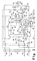
- Figure 2 is a schematic flow diagram of another preferred embodiment of the liquid nitrogen production system of this invention wherein the cold vapor is helium-containing vapor from a helium rejection unit integrated with a nitrogen rejection unit.
- stream 200 comprising methane and nitrogen is cooled and generally partially condensed by passage through heat exchanger 201.
- Stream 200 may contain from 5 to 80 mole percent nitrogen and may be at any pressure, such as from 5.86 to 138 bar (85 to 2000 pounds per square inch absolute (psia)) or more.
- Stream 200 may contain other components in relatively small amounts. The other components include carbon dioxide and higher hydrocarbons such as ethane, propane, i-butane, and n-butane.
- Cooled stream 202 is reduced in pressure by passage through valve 203.
- the pressure reduction through valve 203 generally causes some of stream 202 to vaporize and lowers the temperature of the feed stream.
- Resulting two-phase stream 204 is passed into phase separator 205 wherein it is divided into a vapor portion and a liquid portion.
- the vapor portion which has a greater concentration of nitrogen than does stream 200, is passed as stream 206 through heat exchanger 207 wherein it is condensed.
- the condensed stream 208 is subcooled by passage through subcooler 209.
- Subcooled stream 210 is reduced in pressure by passage through valve 211 and the resulting stream 212 is introduced into column 213 which is operating as a pressure within the range of from 1.03 to 13.8 bar (15 to 200 psia).
- Column 213 may be the column of a single column NRU, one of the columns of a double column NRU, or it may be the upper column of a modified double column NRU as in the embodiment illustrated in Figure 1.
- stream 212 and the other feed stream into column 213 which will be described later are separated by cryogenic rectification into nitrogen-enriched vapor and methane-enriched liquid.
- Stream 212 serves to provide liquid reflux for this cryogenic rectification.
- the liquid portion from phase separator 205 which has a greater concentration of methane than does stream 200, is passed as stream 214 from phase separator 205 and is subcooled by passage through heat exchanger 215.
- Resulting subcooled stream 216 is passed through valve 250 and introduced into column 213 as feed for the aforesaid cryogenic separation into nitrogen-enriched vapor end methane-enriched liquid.
- Methane-enriched liquid is removed from column 213 as stream 217, is pumped to a higher pressure through pump 218, and the resulting stream 219 is warmed by passage through heat exchanger 215 to form stream 220, further warmed by passage through heat exchanger 201 to form stream 221 and recovered as product methane.
- stream 221 has a methane concentration of at least 80 mole percent and typically the methane concentration of stream 221 will be about 95 mole percent or greater.
- Reboiler duty for column 213 is provided by withdrawal of methane-enriched liquid stream 222 and vaporization of this stream by indirect heat exchange with condensing pressurized nitrogen-enriched vapor in heat exchanger 207, as will be more fully described later, as well as vapor stream 206 from phase separator 205. Resulting stream 223 is returned to column 213 for vapor upflow for the column.
- Nitrogen-enriched vapor is removed from column 213 as stream 224.
- This stream serves to provide the cold vapor for the subcooling of the liquid nitrogen.
- Stream 224 is warmed by indirect heat exchange through subcooler 209.
- the resulting stream 225 is divided into streams 226 and 227.
- Stream 226 is warmed by passage through heat exchanger 215 to form stream 228 and further warmed by passage through heat exchanger 201 to form stream 229 which may be recovered, reinjected into an oil or gas reservoir for enhanced hydrocarbon recovery, or simply released to the atmosphere.
- Nitrogen-enriched vapor stream 227 is warmed by passage through heat exchanger 230.
- Resulting warmed stream 231 is increased in pressure, generally to a pressure within the range of from 8.96 to 24.1 bar (130 to 350 psia), by passage through compressor 232 and cooled to remove heat of compression through cooler 233.
- Resulting pressurized nitrogen-enriched vapor 234 is cooled by passage through heat exchanger 230 to produce pressurized nitrogen-enriched vapor stream 235.
- Stream 235 is condensed to produce liquid nitrogen by passage through reboiler 207 by indirect heat exchange with methane-enriched liquid taken as stream 222 from column 213 as was previously described.
- Liquid nitrogen is withdrawn from reboiler 207 as stream 236 and passed to subcooler 209 wherein it is subcooled by indirect heat exchange with cold vapor 224 which generally has a nitrogen concentration greater than 95 mole percent.
- the resulting subcooled liquid nitrogen is passed as stream 237 from subcooler 209 through valve 238 and recovered as product liquid nitrogen in stream 239.
- the production of liquid nitrogen takes advantages of the excess refrigeration available in the process due to the pressure let down of process streams which produces Joule-Thompson refrigeration.
- the subcooling of the liquid nitrogen against cold vapor reduces the amount of nitrogen lost as flash-off vapor.
- FIG. 2 illustrates another embodiment of the invention wherein the cold vapor is helium-containing vapor.
- feed introduced into the column comprising nitrogen and methane is passed into column 106.
- the nitrogen concentration within the feed will be within the range of from 5 to 80 mole percent and the methane concentration within the feed will be within the range of from 20 to 95 mole percent.
- Column 106 may be the column of a single column NRU, one of the columns of a double column NRU, or it may be the upper column of a modified double column NRU as in the embodiment illustrated in Figure 2.
- Column 106 generally is operating at a pressure within the range of from 10.3 to 13.8 bar (150 to 200 psia).
- the feed is separated by cryogenic rectification into a nitrogen-enriched vapor, having a nitrogen concentration which exceeds that of the feed, and into a methane-enriched liquid having a methane concentration which exceeds that of the feed.
- FIG. 2 is another preferred embodiment wherein the NRU system which produces the liquid nitrogen product is integrated with a helium rejection unit (HRU) which produces the helium for the downstream requisite subcooling.
- stream 301 which, for example, may be taken from an upstream stripping column and which contains helium in addition to nitrogen and methane, is cooled and partially condensed by passage through heat exchanger 101.
- Resulting stream 302 is passed through valve 102 and emerges as stream 309 which is passed into phase separator 103.
- Liquid comprising nitrogen and methane is passed out of separator 103 as stream 311 and cooled by passage through heat exchanger 104.
- Resulting stream 313 is passed through valve 105 and emerges as stream 316 which is the feed into NRU column 106.
- Nitrogen-enriched vapor is withdrawn from column 106 as stream 431 which generally has a nitrogen concentration greater than 95 mole percent, is warmed by passage through heat exchangers 109, 104 and 101 and passed out of the system as stream 432. Some of the nitrogen-enriched vapor withdrawn from column 106 and exiting heat exchanger 109, shown in Figure 2 as stream 440, is warmed by passage through heat exchanger 119. Resulting warmed stream 441 is increased in pressure, generally to a pressure within the range of from 8.96 to 33.8 bar (130 to 490 psia), by passage through compressor 117 and cooled to remove heat of compression through cooler 118. Resulting pressurized nitrogen-enriched vapor 443 is cooled by passage through heat exchanger 119 to produce pressurized nitrogen-enriched vapor stream 444.
- Stream 444 is condensed to produce liquid nitrogen by passage through reboiler 107 by indirect heat exchange with methane-enriched liquid taken as stream 411 from column 106.
- the methane-enriched liquid vaporizes by the heat exchange in reboiler 107 and resulting methane-enriched vapor is passed back into column 106 as stream 412 to serve as vapor upflow for the cryogenic rectification.
- Methane liquid generally having a methane concentration within the range of from 90 to 100 mole percent is withdrawn from column 106 as stream 414. This methane liquid is preferably pumped to a higher pressure by passage through liquid pump 116 as illustrated in Figure 2.
- Resulting stream 415 is passed through and heat exchangers 104 and 101 wherein it is warmed and preferably vaporized.
- Resulting stream 418 may be recovered as product methane.
- Liquid nitrogen is taken from reboiler 107 as stream 445 and subcooled by indirect heat exchange with cold vapor in subcooler 120.
- the cold vapor has a helium concentration within the range of from 25 to 100 mole percent, preferably within the range of from 50 to 100 mole percent.
- the resulting subcooled liquid nitrogen is passed as stream 446 from subcooler 120 through valve 124 and recovered as liquid nitrogen product in stream 447.
- the production of liquid nitrogen takes advantage of the excess refrigeration available in the process due to the pressure let down of process streams which produces Joule-Thompson refrigeration.
- the subcooling of the liquid nitrogen against cold helium-containing vapor reduces the amount of nitrogen lost as flash-off vapor.
- the embodiment illustrated in the Figure 2 is a particularly preferred embodiment wherein the NRU is integrated with an HRU and the helium-containing cold vapor employed to subcool the liquid nitrogen is produced by the HRU.
- stream 309 is separated in phase separator 103 into a first fluid enriched in nitrogen and methane which is ultimately passed as feed into column 106, and into a second fluid enriched in helium.
- This second fluid is ultimately employed as the aforesaid helium-containing cold vapor.
- this second fluid undergoes a series of partial condensations prior to being used as the helium-containing cold vapor in subcooler 120.
- helium-containing vapor or second fluid 321 is passed from the vapor side of phase separator 103 through reboiler 107 wherein it is partially condensed. Resulting two phase stream 323 is passed into phase separator 108 and liquid is passed in stream 324 from phase separator 108 through heat exchanger 109. Resulting stream 325 is divided into two portions. A first stream 330 is flashed through valve 110 and passed as two phase stream 327 into column 106. Second stream 331 is throttled across valve 111 and resulting stream 542 is vaporized by passage through heat exchanger 112. Resulting stream 543 is passed into column 106 as additional feed.
- Helium-containing vapor is withdrawn from the vapor-side of phase separator 108 as stream 501 and partially condensed by passage through heat exchanger 112. The resulting fluid is passed out of heat exchanger 112 as stream 502, through valve 113, and as stream 503 into phase separator 114. Liquid is withdrawn from the liquid side of separator 114 as stream 511 passed through valve 115 and passed as stream 512 into the upper portion of column 106 as reflux.
- Helium-containing vapor is withdrawn from the vapor side of separator 114 as stream 521 and employed as the aforesaid helium-containing cold vapor in subcooler 120.
- Resulting stream 522 is warmed by passage through heat exchanger 101 and removed from the system as stream 524.
- Stream 524 may be recovered as crude helium for further processing in a helium refinery.
- the cold vapor employed for the subcooling of the liquid nitrogen will have a temperature generally within the range of from 60 to 125 degrees Kelvin.
- the cold vapor is helium-containing cold vapor, its temperature will generally be in the lower portion of this range.
- the subcooling of the liquid nitrogen by the helium-containing cold vapor need not take place in a separate subcooler but rather these fluids could be passed in countercurrent indirect heat exchange relation through, for example, heat exchanger 109 which would then be the subcooler of the invention.
- the methane-enriched liquid employed to liquefy the nitrogen-enriched vapor need not be taken from the bottom of the column but may be taken from any suitable point in the column.
Description
- This invention relates generally to hydrocarbon processing employing nitrogen rejection systems integrated with a helium processing system.
- One problem often encountered in the production of natural gas from underground reservoirs is nitrogen contamination. The nitrogen may be naturally occurring and/or may have been injected into the reservoir as part of an enhanced oil recovery (EOR) or enhanced gas recovery (EGR) operation. Natural gases which contain a significant amount of nitrogen may not be saleable, since they do not meet minimum heating value specifications and/or exceed maximum inert content requirements. As a result, the feed gas will generally undergo processing, wherein heavier components such as natural gas liquids are initially removed, and then the remaining stream containing primarily nitrogen and methane is separated cryogenically. A common process for separation of nitrogen from natural gas employs a single column or a double column distillation cycle wherein the feed is separated into a nitrogen-enriched vapor and methane-enriched liquid.
- Liquid nitrogen is a desirable product in that it may be employed to provide refrigeration for a process such as a freezing process, or may be stored for subsequent vaporization and use for inerting, nitrogenation or other purposes. The nitrogen generated as a result of a hydrocarbon nitrogen rejection operation is a convenient source of nitrogen. However, production and recovery of nitrogen as liquid is costly because considerable additional equipment is required to use excess refrigeration in the process to condense nitrogen without upsetting the stability and separation efficiency of the process.
- A method for producing nitrogen according to the preamble of claim 1 is known from US-A-4 878 932. The nitrogen-enriched vapor withdrawn from the column is warmed by indirect heat exchange by subsequently passing through three heat exchangers prior to being recovered as product.
- It is an object of this invention to provide a system for the production of liquid nitrogen which is effectively employed in conjunction with a hydrocarbon processing system using a nitrogen rejection unit.
- The above and other objects of which will become apparent to one skilled in the art upon a reading of this disclosure are attained by the present invention, one aspect of which is:
- A method for producing liquid nitrogen comprising:
- (A) passing a feed comprising nitrogen and methane into a column and separating the feed in the column into a nitrogen-enriched vapor and a methane-enriched liquid;
- (B) withdrawing nitrogen-enriched vapor from the column; and
- (C) recovering nitrogen as product;
- (D) in step (B) the pressure of said nitrogen-enriched vapor is increased to produce pressurized nitrogen-enriched vapor;
- (E) said pressurized nitrogen-enriched vapor is condensed by indirect heat exchange with methane-enriched liquid to produce liquid nitrogen; and
- (F) said nitrogen is subcooled by indirect heat exchange with cold vapor prior to being recovered as a liquid product.
- Another aspect of the invention is:
- Apparatus for producing liquid nitrogen according to the methods of claims 1 to 5 comprising:
- (A) a column and means for providing feed into the column;
- (B) a compressor and means for passing vapor from the column to the compressor;
- (C) a reboiler and means for passing vapor from the compressor to the reboiler;
- (D) a subcooler and means for passing liquid from the reboiler to the subcooler; and
- (E) means for recovering liquid from the subcooler.
- The term "column" is used herein to mean a distillation, rectification or fractionation column, i.e., a contacting column or zone wherein liquid and vapor phases are countercurrently contacted to effect separation of a fluid mixture, as for example, by contacting of the vapor and liquid phases on a series of vertically spaced trays or plates mounted within the column, or on packing elements, or a combination thereof. For an expanded discussion of fractionation columns see the Chemical Engineers's Handbook, Fifth Edition, edited by R. H. Perry and C. H. Chilton, Mc-Graw Hill Book Company, New York Section 13, "Distillation" B. D. Smith et al., page 13-3, The Continuous Distillation Process.
- The term "double column", is used herein to mean a high pressure column having its upper end in heat exchange relation with the lower end of a low pressure column. An expanded discussion of double columns appears in Ruheman, "The Separation of Gases" Oxford University Press, 1949, Chapter VII, Commercial Air Separation.
- The terms "nitrogen rejection unit" and "NRU" are used herein to mean a facility wherein nitrogen and methane are separated by cryogenic rectification, comprising a column and the attendant interconnecting equipment such as liquid pumps, phase separators, piping, valves and heat exchangers.
- The term "indirect heat exchange" is used herein to mean the bringing of two fluid streams into heat exchange relation without any physical contact or intermixing of the fluids with each other.
- As used herein the term "phase separator" means a device, in which a two phase fluid separates into vapor and liquid at the vapor side and liquid side respectively.
- As used herein, the term "compressor" means a device for increasing the pressure of a gas.
- As used herein, the term "subcooler" means a device in which a liquid is cooled to a temperature lower than that liquid's saturation temperature for the existing pressure.
- As used herein, the term "liquid nitrogen" means a liquid having a nitrogen concentration of at least 95 mole percent.
- As used herein, the term "reboiler" means a heat exchange device which generates column upflow vapor from column liquid. A reboiler may be physically within or outside a column.
- Figure 1 is a schematic flow diagram of one preferred embodiment of the liquid nitrogen production system of this invention wherein the cold vapor is low pressure nitrogen vapor from a nitrogen rejection unit.
- Figure 2 is a schematic flow diagram of another preferred embodiment of the liquid nitrogen production system of this invention wherein the cold vapor is helium-containing vapor from a helium rejection unit integrated with a nitrogen rejection unit.
- The invention will be described in detail with reference to the Drawings.
- Referring now to Figure 1,
stream 200 comprising methane and nitrogen is cooled and generally partially condensed by passage throughheat exchanger 201.Stream 200 may contain from 5 to 80 mole percent nitrogen and may be at any pressure, such as from 5.86 to 138 bar (85 to 2000 pounds per square inch absolute (psia)) or more. Stream 200 may contain other components in relatively small amounts. The other components include carbon dioxide and higher hydrocarbons such as ethane, propane, i-butane, and n-butane. - Cooled
stream 202 is reduced in pressure by passage throughvalve 203. The pressure reduction throughvalve 203 generally causes some ofstream 202 to vaporize and lowers the temperature of the feed stream. Resulting two-phase stream 204 is passed intophase separator 205 wherein it is divided into a vapor portion and a liquid portion. - The vapor portion, which has a greater concentration of nitrogen than does
stream 200, is passed asstream 206 throughheat exchanger 207 wherein it is condensed. The condensedstream 208 is subcooled by passage throughsubcooler 209.Subcooled stream 210 is reduced in pressure by passage throughvalve 211 and the resultingstream 212 is introduced intocolumn 213 which is operating as a pressure within the range of from 1.03 to 13.8 bar (15 to 200 psia).Column 213 may be the column of a single column NRU, one of the columns of a double column NRU, or it may be the upper column of a modified double column NRU as in the embodiment illustrated in Figure 1. - Within
column 213stream 212 and the other feed stream intocolumn 213 which will be described later are separated by cryogenic rectification into nitrogen-enriched vapor and methane-enriched liquid. Stream 212 serves to provide liquid reflux for this cryogenic rectification. The liquid portion fromphase separator 205, which has a greater concentration of methane than doesstream 200, is passed asstream 214 fromphase separator 205 and is subcooled by passage throughheat exchanger 215. Resultingsubcooled stream 216 is passed throughvalve 250 and introduced intocolumn 213 as feed for the aforesaid cryogenic separation into nitrogen-enriched vapor end methane-enriched liquid. - Methane-enriched liquid is removed from
column 213 asstream 217, is pumped to a higher pressure throughpump 218, and the resultingstream 219 is warmed by passage throughheat exchanger 215 to formstream 220, further warmed by passage throughheat exchanger 201 to formstream 221 and recovered as product methane. Generally stream 221 has a methane concentration of at least 80 mole percent and typically the methane concentration ofstream 221 will be about 95 mole percent or greater. - Reboiler duty for
column 213 is provided by withdrawal of methane-enrichedliquid stream 222 and vaporization of this stream by indirect heat exchange with condensing pressurized nitrogen-enriched vapor inheat exchanger 207, as will be more fully described later, as well asvapor stream 206 fromphase separator 205. Resultingstream 223 is returned tocolumn 213 for vapor upflow for the column. - Nitrogen-enriched vapor is removed from
column 213 asstream 224. This stream serves to provide the cold vapor for the subcooling of the liquid nitrogen.Stream 224 is warmed by indirect heat exchange throughsubcooler 209. The resultingstream 225 is divided intostreams Stream 226 is warmed by passage throughheat exchanger 215 to formstream 228 and further warmed by passage throughheat exchanger 201 to formstream 229 which may be recovered, reinjected into an oil or gas reservoir for enhanced hydrocarbon recovery, or simply released to the atmosphere. - Nitrogen-enriched
vapor stream 227 is warmed by passage throughheat exchanger 230. Resulting warmedstream 231 is increased in pressure, generally to a pressure within the range of from 8.96 to 24.1 bar (130 to 350 psia), by passage throughcompressor 232 and cooled to remove heat of compression through cooler 233. Resulting pressurized nitrogen-enrichedvapor 234 is cooled by passage throughheat exchanger 230 to produce pressurized nitrogen-enrichedvapor stream 235. -
Stream 235 is condensed to produce liquid nitrogen by passage throughreboiler 207 by indirect heat exchange with methane-enriched liquid taken asstream 222 fromcolumn 213 as was previously described. Liquid nitrogen is withdrawn fromreboiler 207 asstream 236 and passed to subcooler 209 wherein it is subcooled by indirect heat exchange withcold vapor 224 which generally has a nitrogen concentration greater than 95 mole percent. The resulting subcooled liquid nitrogen is passed asstream 237 fromsubcooler 209 throughvalve 238 and recovered as product liquid nitrogen instream 239. The production of liquid nitrogen takes advantages of the excess refrigeration available in the process due to the pressure let down of process streams which produces Joule-Thompson refrigeration. The subcooling of the liquid nitrogen against cold vapor reduces the amount of nitrogen lost as flash-off vapor. - Figure 2 illustrates another embodiment of the invention wherein the cold vapor is helium-containing vapor. Referring now to Figure 2, feed introduced into the column comprising nitrogen and methane is passed into
column 106. Typically the nitrogen concentration within the feed will be within the range of from 5 to 80 mole percent and the methane concentration within the feed will be within the range of from 20 to 95 mole percent.Column 106 may be the column of a single column NRU, one of the columns of a double column NRU, or it may be the upper column of a modified double column NRU as in the embodiment illustrated in Figure 2.Column 106 generally is operating at a pressure within the range of from 10.3 to 13.8 bar (150 to 200 psia). - Within
column 106 the feed is separated by cryogenic rectification into a nitrogen-enriched vapor, having a nitrogen concentration which exceeds that of the feed, and into a methane-enriched liquid having a methane concentration which exceeds that of the feed. - The embodiment illustrated in Figure 2 is another preferred embodiment wherein the NRU system which produces the liquid nitrogen product is integrated with a helium rejection unit (HRU) which produces the helium for the downstream requisite subcooling. In this
embodiment stream 301, which, for example, may be taken from an upstream stripping column and which contains helium in addition to nitrogen and methane, is cooled and partially condensed by passage throughheat exchanger 101. Resultingstream 302 is passed throughvalve 102 and emerges asstream 309 which is passed intophase separator 103. Liquid comprising nitrogen and methane is passed out ofseparator 103 asstream 311 and cooled by passage throughheat exchanger 104. Resultingstream 313 is passed throughvalve 105 and emerges asstream 316 which is the feed intoNRU column 106. - Nitrogen-enriched vapor is withdrawn from
column 106 asstream 431 which generally has a nitrogen concentration greater than 95 mole percent, is warmed by passage throughheat exchangers stream 432. Some of the nitrogen-enriched vapor withdrawn fromcolumn 106 and exitingheat exchanger 109, shown in Figure 2 asstream 440, is warmed by passage throughheat exchanger 119. Resulting warmedstream 441 is increased in pressure, generally to a pressure within the range of from 8.96 to 33.8 bar (130 to 490 psia), by passage throughcompressor 117 and cooled to remove heat of compression through cooler 118. Resulting pressurized nitrogen-enrichedvapor 443 is cooled by passage throughheat exchanger 119 to produce pressurized nitrogen-enrichedvapor stream 444. -
Stream 444 is condensed to produce liquid nitrogen by passage throughreboiler 107 by indirect heat exchange with methane-enriched liquid taken asstream 411 fromcolumn 106. The methane-enriched liquid vaporizes by the heat exchange inreboiler 107 and resulting methane-enriched vapor is passed back intocolumn 106 asstream 412 to serve as vapor upflow for the cryogenic rectification. Methane liquid, generally having a methane concentration within the range of from 90 to 100 mole percent is withdrawn fromcolumn 106 asstream 414. This methane liquid is preferably pumped to a higher pressure by passage throughliquid pump 116 as illustrated in Figure 2. Resultingstream 415 is passed through andheat exchangers stream 418 may be recovered as product methane. - Liquid nitrogen is taken from
reboiler 107 asstream 445 and subcooled by indirect heat exchange with cold vapor insubcooler 120. The cold vapor has a helium concentration within the range of from 25 to 100 mole percent, preferably within the range of from 50 to 100 mole percent. The resulting subcooled liquid nitrogen is passed asstream 446 fromsubcooler 120 throughvalve 124 and recovered as liquid nitrogen product instream 447. The production of liquid nitrogen takes advantage of the excess refrigeration available in the process due to the pressure let down of process streams which produces Joule-Thompson refrigeration. The subcooling of the liquid nitrogen against cold helium-containing vapor reduces the amount of nitrogen lost as flash-off vapor. - As mentioned, the embodiment illustrated in the Figure 2 is a particularly preferred embodiment wherein the NRU is integrated with an HRU and the helium-containing cold vapor employed to subcool the liquid nitrogen is produced by the HRU. As previously described,
stream 309 is separated inphase separator 103 into a first fluid enriched in nitrogen and methane which is ultimately passed as feed intocolumn 106, and into a second fluid enriched in helium. This second fluid is ultimately employed as the aforesaid helium-containing cold vapor. In the embodiment illustrated in Figure 2 this second fluid undergoes a series of partial condensations prior to being used as the helium-containing cold vapor insubcooler 120. - Referring back now to Figure 2, helium-containing vapor or
second fluid 321 is passed from the vapor side ofphase separator 103 throughreboiler 107 wherein it is partially condensed. Resulting twophase stream 323 is passed intophase separator 108 and liquid is passed instream 324 fromphase separator 108 throughheat exchanger 109. Resultingstream 325 is divided into two portions. Afirst stream 330 is flashed throughvalve 110 and passed as twophase stream 327 intocolumn 106.Second stream 331 is throttled acrossvalve 111 and resultingstream 542 is vaporized by passage throughheat exchanger 112. Resultingstream 543 is passed intocolumn 106 as additional feed. - Helium-containing vapor is withdrawn from the vapor-side of
phase separator 108 asstream 501 and partially condensed by passage throughheat exchanger 112. The resulting fluid is passed out ofheat exchanger 112 asstream 502, throughvalve 113, and asstream 503 intophase separator 114. Liquid is withdrawn from the liquid side ofseparator 114 asstream 511 passed throughvalve 115 and passed asstream 512 into the upper portion ofcolumn 106 as reflux. Helium-containing vapor is withdrawn from the vapor side ofseparator 114 asstream 521 and employed as the aforesaid helium-containing cold vapor insubcooler 120. Resultingstream 522 is warmed by passage throughheat exchanger 101 and removed from the system asstream 524.Stream 524 may be recovered as crude helium for further processing in a helium refinery. - In the practice of this invention the cold vapor employed for the subcooling of the liquid nitrogen will have a temperature generally within the range of from 60 to 125 degrees Kelvin. When the cold vapor is helium-containing cold vapor, its temperature will generally be in the lower portion of this range.
- Although the invention has been described in detail with reference to a certain preferred embodiments, the subcooling of the liquid nitrogen by the helium-containing cold vapor need not take place in a separate subcooler but rather these fluids could be passed in countercurrent indirect heat exchange relation through, for example,
heat exchanger 109 which would then be the subcooler of the invention. In addition, the methane-enriched liquid employed to liquefy the nitrogen-enriched vapor need not be taken from the bottom of the column but may be taken from any suitable point in the column.
Claims (9)
- A method for producing liquid nitrogen comprising:(A) passing a feed (216, 316) comprising nitrogen and methane into a column (106, 213) and separating the feed in the column into a nitrogen-enriched vapor (224, 431) and a methane-enriched liquid (217, 222; 411, 414);(B) withdrawing nitrogen-enriched vapor (224, 431) from the column (106, 213); and(C) recovering nitrogen as product (239, 447);characterized in that(D) in step (B) the pressure of said nitrogen-enriched vapor (224, 431) is increased to produce pressurized nitrogen-enriched vapor (234, 443);(E) said pressurized nitrogen-enriched vapor (234, 443) is condensed by indirect heat exchange with methane-enriched liquid (222, 411) to produce liquid nitrogen (237, 446); and(F) said nitrogen (237, 446) is subcooled by indirect heat exchange with cold vapor (224, 521) prior to being recovered as liquid product (239, 447).
- The method of claim 1 wherein the cold vapor (224) has a nitrogen concentration greater than 95 mole percent:
- The method of claim 1 further comprising providing a stream (301) containing nitrogen, methane and helium, separating this stream into a first fluid (311) enriched in nitrogen and methane and into a second fluid (321) enriched in helium, employing the first fluid as said feed (316) passed into the column (106), and employing the second fluid as said cold vapor (521) having a helium concentration within the range from 25 to 100 mole percent.
- The method of claim 3 further comprising partially condensing the second fluid (321), employing resulting vapor as said helium containing vapor (521), and passing resulting liquid (324, 511) into the column (106).
- The method of claim 4 wherein the second fluid (321) is partially condensed by indirect heat exchange with methane-enriched liquid (411).
- Apparatus for producing liquid nitrogen according to the methods of claims 1 to 5 comprising(A) a column (106, 213) and means for providing feed into the column;(B) a compressor (117, 232) and means for passing vapor from the column (106, 213) to the compressor;(C) a reboiler (107, 207) and means for passing vapor from the compressor (117, 232) to the reboiler;(D) a subcooler (120, 209) and means for passing liquid from the reboiler (107, 207) to the subcooler; and(E) means for recovering liquid from the subcooler (120, 209).
- The apparatus of claim 6 further comprising a phase separator (103, 205), means for passing fluid from the lower portion of the phase separator as feed into the column (106, 213) and means for passing fluid from the upper portion of the phase separator to the subcooler (120, 209).
- The apparatus of claim 7 wherein the means for passing the fluid from the upper portion of the phase separator (103) to the subcooler (120) includes at least one other phase separator (108, 114) and at least one heat exchanger (107, 112).
- The apparatus of claim 8 wherein said at least one heat exchanger includes said reboiler (107).
Applications Claiming Priority (2)
| Application Number | Priority Date | Filing Date | Title |
|---|---|---|---|
| US08/088,499 US5339641A (en) | 1993-07-07 | 1993-07-07 | Cryogenic liquid nitrogen production system |
| US88499 | 1998-06-01 |
Publications (2)
| Publication Number | Publication Date |
|---|---|
| EP0633437A1 EP0633437A1 (en) | 1995-01-11 |
| EP0633437B1 true EP0633437B1 (en) | 1997-04-09 |
Family
ID=22211723
Family Applications (1)
| Application Number | Title | Priority Date | Filing Date |
|---|---|---|---|
| EP94110470A Expired - Lifetime EP0633437B1 (en) | 1993-07-07 | 1994-07-06 | Cryogenic liquid nitrogen production system and apparatus |
Country Status (8)
| Country | Link |
|---|---|
| US (1) | US5339641A (en) |
| EP (1) | EP0633437B1 (en) |
| BR (1) | BR9402647A (en) |
| CA (1) | CA2127523C (en) |
| DE (1) | DE69402474T2 (en) |
| ES (1) | ES2100002T3 (en) |
| NO (1) | NO305727B1 (en) |
| ZA (1) | ZA944891B (en) |
Families Citing this family (12)
| Publication number | Priority date | Publication date | Assignee | Title |
|---|---|---|---|---|
| US5638698A (en) * | 1996-08-22 | 1997-06-17 | Praxair Technology, Inc. | Cryogenic system for producing nitrogen |
| US5771714A (en) * | 1997-08-01 | 1998-06-30 | Praxair Technology, Inc. | Cryogenic rectification system for producing higher purity helium |
| US6411061B1 (en) | 1999-12-14 | 2002-06-25 | Delphi Technologies, Inc. | High performance brush motor driver in conjuction with low cost SR motor driver |
| DE10055321A1 (en) * | 2000-11-08 | 2002-05-16 | Gea Happel Klimatechnik | Method of condensing gases involves condensing gas mixture to allow separation of lower condensation temperature gas |
| GB0116960D0 (en) * | 2001-07-11 | 2001-09-05 | Boc Group Plc | Nitrogen rejection method and apparatus |
| US20080314079A1 (en) * | 2007-06-19 | 2008-12-25 | Air Products And Chemicals, Inc. | Nitrogen Rejection Column Reboiler Configuration |
| US20100077796A1 (en) * | 2008-09-30 | 2010-04-01 | Sarang Gadre | Hybrid Membrane/Distillation Method and System for Removing Nitrogen from Methane |
| FR2936864B1 (en) * | 2008-10-07 | 2010-11-26 | Technip France | PROCESS FOR THE PRODUCTION OF LIQUID AND GASEOUS NITROGEN CURRENTS, A HELIUM RICH GASEOUS CURRENT AND A DEAZOTE HYDROCARBON CURRENT, AND ASSOCIATED PLANT. |
| EP2350546A1 (en) * | 2008-10-07 | 2011-08-03 | Exxonmobil Upstream Research Company | Helium recovery from natural gas integrated with ngl recovery |
| WO2014178058A1 (en) | 2013-05-01 | 2014-11-06 | Fertilesafe Ltd | Devices and methods for producing liquid air |
| FR3035656B1 (en) * | 2015-04-30 | 2019-03-22 | L'air Liquide, Societe Anonyme Pour L'etude Et L'exploitation Des Procedes Georges Claude | PRODUCTION OF HELIUM FROM A GASEOUS CURRENT CONTAINING HYDROGEN |
| US10215488B2 (en) | 2016-02-11 | 2019-02-26 | Air Products And Chemicals, Inc. | Treatment of nitrogen-rich natural gas streams |
Family Cites Families (14)
| Publication number | Priority date | Publication date | Assignee | Title |
|---|---|---|---|---|
| US3324626A (en) * | 1964-12-03 | 1967-06-13 | Sinclair Research Inc | Process for the recovery of helium |
| US3531943A (en) * | 1965-10-23 | 1970-10-06 | Aerojet General Co | Cryogenic process for separation of a natural gas with a high nitrogen content |
| DE2734080A1 (en) * | 1977-07-28 | 1979-02-15 | Linde Ag | METHOD FOR SEPARATING METHANE FROM A RAW GAS CONTAINING METHANE |
| US4415345A (en) * | 1982-03-26 | 1983-11-15 | Union Carbide Corporation | Process to separate nitrogen from natural gas |
| US4501600A (en) * | 1983-07-15 | 1985-02-26 | Union Carbide Corporation | Process to separate nitrogen from natural gas |
| US4592767A (en) * | 1985-05-29 | 1986-06-03 | Union Carbide Corporation | Process for separating methane and nitrogen |
| US4664686A (en) * | 1986-02-07 | 1987-05-12 | Union Carbide Corporation | Process to separate nitrogen and methane |
| US4734115A (en) * | 1986-03-24 | 1988-03-29 | Air Products And Chemicals, Inc. | Low pressure process for C3+ liquids recovery from process product gas |
| US4710212A (en) * | 1986-09-24 | 1987-12-01 | Union Carbide Corporation | Process to produce high pressure methane gas |
| US4732598A (en) * | 1986-11-10 | 1988-03-22 | Air Products And Chemicals, Inc. | Dephlegmator process for nitrogen rejection from natural gas |
| US4878932A (en) * | 1989-03-21 | 1989-11-07 | Union Carbide Corporation | Cryogenic rectification process for separating nitrogen and methane |
| US4948404A (en) * | 1989-08-03 | 1990-08-14 | Phillips Petroleum Company | Liquid nitrogen by-product production in an NGL plant |
| US5026408A (en) * | 1990-06-01 | 1991-06-25 | Union Carbide Industrial Gases Technology Corporation | Methane recovery process for the separation of nitrogen and methane |
| US5041149A (en) * | 1990-10-18 | 1991-08-20 | Union Carbide Industrial Gases Technology Corporation | Separation of nitrogen and methane with residue turboexpansion |
-
1993
- 1993-07-07 US US08/088,499 patent/US5339641A/en not_active Expired - Lifetime
-
1994
- 1994-07-06 CA CA002127523A patent/CA2127523C/en not_active Expired - Fee Related
- 1994-07-06 DE DE69402474T patent/DE69402474T2/en not_active Expired - Fee Related
- 1994-07-06 EP EP94110470A patent/EP0633437B1/en not_active Expired - Lifetime
- 1994-07-06 ES ES94110470T patent/ES2100002T3/en not_active Expired - Lifetime
- 1994-07-06 NO NO942556A patent/NO305727B1/en not_active IP Right Cessation
- 1994-07-06 BR BR9402647A patent/BR9402647A/en not_active IP Right Cessation
- 1994-07-06 ZA ZA944891A patent/ZA944891B/en unknown
Also Published As
| Publication number | Publication date |
|---|---|
| DE69402474D1 (en) | 1997-05-15 |
| NO942556D0 (en) | 1994-07-06 |
| ZA944891B (en) | 1995-02-20 |
| EP0633437A1 (en) | 1995-01-11 |
| CA2127523A1 (en) | 1995-01-08 |
| US5339641A (en) | 1994-08-23 |
| DE69402474T2 (en) | 1997-10-23 |
| CA2127523C (en) | 1997-07-01 |
| ES2100002T3 (en) | 1997-06-01 |
| NO942556L (en) | 1995-01-09 |
| NO305727B1 (en) | 1999-07-12 |
| BR9402647A (en) | 1995-04-04 |
Similar Documents
| Publication | Publication Date | Title |
|---|---|---|
| CA2012611C (en) | Cryogenic rectification process for separating nitrogen and methane | |
| US4411677A (en) | Nitrogen rejection from natural gas | |
| EP0231949B2 (en) | Process to separate nitrogen and methane | |
| US4710212A (en) | Process to produce high pressure methane gas | |
| US6662589B1 (en) | Integrated high pressure NGL recovery in the production of liquefied natural gas | |
| US5051120A (en) | Feed processing for nitrogen rejection unit | |
| US5983665A (en) | Production of refrigerated liquid methane | |
| US20080016910A1 (en) | Integrated NGL recovery in the production of liquefied natural gas | |
| US5041149A (en) | Separation of nitrogen and methane with residue turboexpansion | |
| US4479871A (en) | Process to separate natural gas liquids from nitrogen-containing natural gas | |
| US4592767A (en) | Process for separating methane and nitrogen | |
| US5329775A (en) | Cryogenic helium production system | |
| US5017204A (en) | Dephlegmator process for the recovery of helium | |
| US5564290A (en) | Cryogenic rectification system with dual phase turboexpansion | |
| EP0633437B1 (en) | Cryogenic liquid nitrogen production system and apparatus | |
| US4732598A (en) | Dephlegmator process for nitrogen rejection from natural gas | |
| EP0742415B1 (en) | Process for removing nitrogen from LNG | |
| CA1269039A (en) | Method and apparatus for purification of high n.sub.2 content gas | |
| US5026408A (en) | Methane recovery process for the separation of nitrogen and methane | |
| US5802871A (en) | Dephlegmator process for nitrogen removal from natural gas | |
| US5771714A (en) | Cryogenic rectification system for producing higher purity helium | |
| CA1295932C (en) | Process to produce cold helium gas for liquefaction | |
| GB2304401A (en) | Recompression cycle for recovery of natural gas liquids | |
| US5386691A (en) | Cryogenic air separation system with kettle vapor bypass |
Legal Events
| Date | Code | Title | Description |
|---|---|---|---|
| PUAI | Public reference made under article 153(3) epc to a published international application that has entered the european phase |
Free format text: ORIGINAL CODE: 0009012 |
|
| AK | Designated contracting states |
Kind code of ref document: A1 Designated state(s): DE ES GB IT NL |
|
| 17P | Request for examination filed |
Effective date: 19950217 |
|
| 17Q | First examination report despatched |
Effective date: 19960311 |
|
| GRAG | Despatch of communication of intention to grant |
Free format text: ORIGINAL CODE: EPIDOS AGRA |
|
| GRAH | Despatch of communication of intention to grant a patent |
Free format text: ORIGINAL CODE: EPIDOS IGRA |
|
| GRAH | Despatch of communication of intention to grant a patent |
Free format text: ORIGINAL CODE: EPIDOS IGRA |
|
| GRAA | (expected) grant |
Free format text: ORIGINAL CODE: 0009210 |
|
| ITF | It: translation for a ep patent filed |
Owner name: 0403;01RMFBARZANO' E ZANARDO ROMA S.P.A. |
|
| AK | Designated contracting states |
Kind code of ref document: B1 Designated state(s): DE ES GB IT NL |
|
| REF | Corresponds to: |
Ref document number: 69402474 Country of ref document: DE Date of ref document: 19970515 |
|
| REG | Reference to a national code |
Ref country code: ES Ref legal event code: FG2A Ref document number: 2100002 Country of ref document: ES Kind code of ref document: T3 |
|
| PLBE | No opposition filed within time limit |
Free format text: ORIGINAL CODE: 0009261 |
|
| STAA | Information on the status of an ep patent application or granted ep patent |
Free format text: STATUS: NO OPPOSITION FILED WITHIN TIME LIMIT |
|
| 26N | No opposition filed | ||
| PGFP | Annual fee paid to national office [announced via postgrant information from national office to epo] |
Ref country code: GB Payment date: 19990622 Year of fee payment: 6 Ref country code: NL Payment date: 19990622 Year of fee payment: 6 |
|
| PGFP | Annual fee paid to national office [announced via postgrant information from national office to epo] |
Ref country code: DE Payment date: 19990623 Year of fee payment: 6 |
|
| PGFP | Annual fee paid to national office [announced via postgrant information from national office to epo] |
Ref country code: ES Payment date: 19990715 Year of fee payment: 6 |
|
| PG25 | Lapsed in a contracting state [announced via postgrant information from national office to epo] |
Ref country code: GB Free format text: LAPSE BECAUSE OF NON-PAYMENT OF DUE FEES Effective date: 20000706 |
|
| PG25 | Lapsed in a contracting state [announced via postgrant information from national office to epo] |
Ref country code: ES Free format text: LAPSE BECAUSE OF NON-PAYMENT OF DUE FEES Effective date: 20000707 |
|
| PG25 | Lapsed in a contracting state [announced via postgrant information from national office to epo] |
Ref country code: NL Free format text: LAPSE BECAUSE OF NON-PAYMENT OF DUE FEES Effective date: 20010201 |
|
| GBPC | Gb: european patent ceased through non-payment of renewal fee |
Effective date: 20000706 |
|
| NLV4 | Nl: lapsed or anulled due to non-payment of the annual fee |
Effective date: 20010201 |
|
| PG25 | Lapsed in a contracting state [announced via postgrant information from national office to epo] |
Ref country code: DE Free format text: LAPSE BECAUSE OF NON-PAYMENT OF DUE FEES Effective date: 20010501 |
|
| REG | Reference to a national code |
Ref country code: ES Ref legal event code: FD2A Effective date: 20010810 |
|
| PG25 | Lapsed in a contracting state [announced via postgrant information from national office to epo] |
Ref country code: IT Free format text: LAPSE BECAUSE OF NON-PAYMENT OF DUE FEES Effective date: 20050706 |