EP0632674B1 - Method of producing a diaphragm for use with an electro-acoustic transducer - Google Patents
Method of producing a diaphragm for use with an electro-acoustic transducer Download PDFInfo
- Publication number
- EP0632674B1 EP0632674B1 EP94304667A EP94304667A EP0632674B1 EP 0632674 B1 EP0632674 B1 EP 0632674B1 EP 94304667 A EP94304667 A EP 94304667A EP 94304667 A EP94304667 A EP 94304667A EP 0632674 B1 EP0632674 B1 EP 0632674B1
- Authority
- EP
- European Patent Office
- Prior art keywords
- diaphragm
- molding
- edge
- edge portion
- cavity
- Prior art date
- Legal status (The legal status is an assumption and is not a legal conclusion. Google has not performed a legal analysis and makes no representation as to the accuracy of the status listed.)
- Expired - Lifetime
Links
Images


Classifications
-
- H—ELECTRICITY
- H04—ELECTRIC COMMUNICATION TECHNIQUE
- H04R—LOUDSPEAKERS, MICROPHONES, GRAMOPHONE PICK-UPS OR LIKE ACOUSTIC ELECTROMECHANICAL TRANSDUCERS; ELECTRIC HEARING AIDS; PUBLIC ADDRESS SYSTEMS
- H04R31/00—Apparatus or processes specially adapted for the manufacture of transducers or diaphragms therefor
- H04R31/003—Apparatus or processes specially adapted for the manufacture of transducers or diaphragms therefor for diaphragms or their outer suspension
-
- B—PERFORMING OPERATIONS; TRANSPORTING
- B29—WORKING OF PLASTICS; WORKING OF SUBSTANCES IN A PLASTIC STATE IN GENERAL
- B29C—SHAPING OR JOINING OF PLASTICS; SHAPING OF MATERIAL IN A PLASTIC STATE, NOT OTHERWISE PROVIDED FOR; AFTER-TREATMENT OF THE SHAPED PRODUCTS, e.g. REPAIRING
- B29C45/00—Injection moulding, i.e. forcing the required volume of moulding material through a nozzle into a closed mould; Apparatus therefor
- B29C45/16—Making multilayered or multicoloured articles
- B29C45/1635—Making multilayered or multicoloured articles using displaceable mould parts, e.g. retractable partition between adjacent mould cavities
- B29C45/1639—Removable partitions between adjacent mould cavity portions
-
- H—ELECTRICITY
- H04—ELECTRIC COMMUNICATION TECHNIQUE
- H04R—LOUDSPEAKERS, MICROPHONES, GRAMOPHONE PICK-UPS OR LIKE ACOUSTIC ELECTROMECHANICAL TRANSDUCERS; ELECTRIC HEARING AIDS; PUBLIC ADDRESS SYSTEMS
- H04R3/00—Circuits for transducers
-
- H—ELECTRICITY
- H04—ELECTRIC COMMUNICATION TECHNIQUE
- H04R—LOUDSPEAKERS, MICROPHONES, GRAMOPHONE PICK-UPS OR LIKE ACOUSTIC ELECTROMECHANICAL TRANSDUCERS; ELECTRIC HEARING AIDS; PUBLIC ADDRESS SYSTEMS
- H04R7/00—Diaphragms for electromechanical transducers; Cones
- H04R7/16—Mounting or tensioning of diaphragms or cones
- H04R7/18—Mounting or tensioning of diaphragms or cones at the periphery
- H04R7/20—Securing diaphragm or cone resiliently to support by flexible material, springs, cords, or strands
-
- H—ELECTRICITY
- H04—ELECTRIC COMMUNICATION TECHNIQUE
- H04R—LOUDSPEAKERS, MICROPHONES, GRAMOPHONE PICK-UPS OR LIKE ACOUSTIC ELECTROMECHANICAL TRANSDUCERS; ELECTRIC HEARING AIDS; PUBLIC ADDRESS SYSTEMS
- H04R2231/00—Details of apparatus or processes specially adapted for the manufacture of transducers or diaphragms therefor covered by H04R31/00, not provided for in its subgroups
- H04R2231/003—Manufacturing aspects of the outer suspension of loudspeaker or microphone diaphragms or of their connecting aspects to said diaphragms
-
- H—ELECTRICITY
- H04—ELECTRIC COMMUNICATION TECHNIQUE
- H04R—LOUDSPEAKERS, MICROPHONES, GRAMOPHONE PICK-UPS OR LIKE ACOUSTIC ELECTROMECHANICAL TRANSDUCERS; ELECTRIC HEARING AIDS; PUBLIC ADDRESS SYSTEMS
- H04R2307/00—Details of diaphragms or cones for electromechanical transducers, their suspension or their manufacture covered by H04R7/00 or H04R31/003, not provided for in any of its subgroups
- H04R2307/029—Diaphragms comprising fibres
-
- Y—GENERAL TAGGING OF NEW TECHNOLOGICAL DEVELOPMENTS; GENERAL TAGGING OF CROSS-SECTIONAL TECHNOLOGIES SPANNING OVER SEVERAL SECTIONS OF THE IPC; TECHNICAL SUBJECTS COVERED BY FORMER USPC CROSS-REFERENCE ART COLLECTIONS [XRACs] AND DIGESTS
- Y10—TECHNICAL SUBJECTS COVERED BY FORMER USPC
- Y10T—TECHNICAL SUBJECTS COVERED BY FORMER US CLASSIFICATION
- Y10T29/00—Metal working
- Y10T29/49—Method of mechanical manufacture
- Y10T29/49002—Electrical device making
- Y10T29/49005—Acoustic transducer
Definitions
- the present invention relates to a method of producing a diaphragm for use with an electro-acoustic transducer and, more particularly, to a method of producing a diaphragm for use with an electro-acoustic transducer by using synthetic resin materials.
- diaphragm As background to the invention a known method of producing a diaphragm for use with an electro-acoustic transducer will be described below with reference to Figures 1a to 1d and Figures 2a to 2c of the accompanying drawings.
- the above-mentioned diaphragm for use with an electro-acoustic transducer will be referred to hereinafter simply as "diaphragm”.
- a member 31 of substantially truncated cone configuration shown in FIGURE 1a is produced.
- the substantially truncated cone-shaped member 31 is produced by some suitable methods, such as sheet-making of paper and pulp, pressing of polymer film under heating or injection-molding of olefin thermoplastic resin.
- the substantially truncated cone-shaped member 31 is cut out at its portion shown by a one-dot chain line in FIGURE 1a to provide an outer diameter portion 32 and a bottom portion 33.
- the member 31 is manufactured as a cone-shaped diaphragm member 34 shown in FIGURE 1b.
- a member 37 of substantially saucer configuration shown in FIGURE 1c is produced by heating and molding a material, such as cotton cloth, rubber, polyurethan foam, elastomer or the like.
- the substantially saucer-shaped member 37 is cut out at its positions of diameters ⁇ A and ⁇ B shown by one-dot chain lines in FIGURE 1c to provide an outer peripheral portion and an inner peripheral portion.
- the substantially saucer-shaped member 37 is manufactured as an annular-shaped edge member 38 shown in FIGURE 1d.
- the edge member 38 includes an edge portion 38a of substantially U-shaped cross section.
- the diaphragm member 34 is coated at its outer surface portion of the outer peripheral side with an adhesive 35 as shown in FIGURE 2a.
- the edge member 38 is positioned on a mold 41 by engaging the edge portion 38a of the edge member 38 with a protrusion 41a of the mold 41 of the molds 40 and 41. Under this condition, an opening portion 34a of the diaphragm member 34 is fitted onto a columnar portion 41b by downwardly inserting the diaphragm member 34 into the mold 41.
- the diaphragm member 34 is positioned on the mold 41. Subsequently, the mold is closed by lowering the mold 40 of the molds 40, 41 in FIGURE 2b, and the diaphragm 34 and the edge member 38 are pressed. In this case, the molds 40, 41 are heated at a predetermined temperature, the adhesive 35 is cured under pressure produced when the molds 40, 41 are pressed. Consequently, as shown in FIGURE 2c, the diaphragm member 34 and the edge member 38 are joined together.
- the diaphragm member 34 and the edge member 38 are produced separately, and the diaphragm member 34 and the edge member 38 are manufactured as the predetermined shapes, whereafter the diaphragm member 34 and the edge member 38 are bonded together by the adhesive 35.
- a pre-treatment should be carried out in order to improve an adhesive property.
- the pre-treatment after the diaphragm member 34 and the edge member 38 are manufactured as the predetermined shapes, either or both of the diaphragm member 34 and the edge member 38 are coated with a primer, whereafter the adhesive 35 is coated on the diaphragm member 34 and the diaphragm member 34 and the edge member 38 are bonded together by means of the adhesive 35. Therefore, the number of manufacturing processes is increased, which unavoidably increases the manufacturing cost of the diaphragm.
- the diaphragm member 34 and the edge member 38 should be bonded under the condition that a center of the diaphragm member 34 and a center of the edge member 38 are coincident with each other. If the center of the diaphragm member 34 and the center of the edge member 38 are displaced from each other after the diaphragm member 34 and the edge member 38 are bonded together, then the diaphragm cannot be vibrated correctly. Particularly, in the speaker apparatus of dynamic type, when the diaphragm is displaced in position, a voice coil bobbin that is attached to the diaphragm member also is displaced in position. There is then the new problem that a magnetic circuit is disturbed by the voice coil bobbin.
- the acoustic characteristic of the diaphragm and the quality of the diaphragm are influenced by the cured state of the adhesive and the types of the adhesives or the joined state of the diaphragm member and the edge member.
- the characteristic of the diaphragm thus mass-produced tends to become irregular. Therefore, it becomes impossible to obtain a diaphragm of high reliability.
- the diaphragm thus produced is used, it becomes impossible to mass-produce speaker apparatus of uniform tone quality.
- US-A-3,961,378, on which the two part form of claim 1 is based, discloses a method of molding a diaphragm for use with an electro-acoustic transducer and having a diaphragm portion and an edge portion joined by mutually overlying portions at an outer peripheral side of the diaphragm portion.
- the method comprises: a first step of molding the diaphragm portion in a first cavity; and a second step of molding in a second cavity the edge portion to the molded diaphragm portion to join the mutually overlying portions of the diaphragm portion and the edge portion.
- the diaphragm portion After the diaphragm portion has been pre-molded in the first step, it is interposed in position in another mold defining the second cavity to perform the second molding step.
- JP-A-58,201,496 discloses a method of molding a diaphragm for use with an electro-acoustic transducer and having a diaphragm portion and an edge portion joined by mutually overlying portions at an outer peripheral side of the diaphragm portion.
- the method comprises: a first step of molding the diaphragm portion in a first cavity; and a second step of molding in a second cavity the edge portion to the molded diaphragm portion to join the mutually overlying portions of the diaphragm portion and the edge portion.
- the upper side of the first cavity for the first molding step is defined by a first die. After the first molding step, the first die is removed and replaced by a different second die defining the second cavity to perform the second molding step.
- GB-A-2,228,391 discloses a method of molding a diaphragm for use with an electrode-acoustic transducer and having a diaphragm portion and an edge portion joined edge-to-edge at an outer peripheral edge of the diaphragm portion.
- the method comprises: a first step of molding the edge portion in a first cavity; and a second step of molding a second cavity the diaphragm portion to the edge portion to join the edges of the diaphragm portion and the edge portion.
- the method is performed using a mold having a movable mold member which is movable from a first position, where the movable mold member closes off the second cavity, to a second position, where the movable mold member opens to define the second cavity.
- the first molding step is performed with the movable mold member in its first position and the second molding step is performed with the movable mold member in its second position.
- a method of molding a diaphragm for use with an electro-acoustic transducer said diaphragm having a diaphragm portion and an edge portion joined by mutually overlying portions at an outer peripheral side of the diaphragm portion, the method comprising:
- the diaphragm portion and the edge portion of the diaphragm for use with an electro-acoustic transducer are integrally molded by dichromatic molding, it becomes possible to mold respective portions of the edge portion and the diaphragm portion by materials selected to provide desirable characteristics for the respective portions. Further, since the edge portion and the diaphragm portion are integrally molded together, it becomes possible to simplify the manufacturing process of the diaphragm. Also, it becomes possible to prevent the edge portion and the diaphragm portion from being detached as occurs when an adhesive for bonding the edge portion and the diaphragm portion is deteriorated.
- edge portion and the diaphragm portion are molded integrally, it is possible to prevent the center of the edge portion and the center of the diaphragm portion from being displaced from each other.
- a substance, such as an adhesive or the like is not interposed between the edge portion and the diaphragm portion, it is possible to avoid a frequency characteristic from being deteriorated.
- diaphragm A method of producing a diaphragm for use with an electro-acoustic transducer (referred to hereinafter simply as “diaphragm") according to an embodiment of the present invention will be described below with reference to the drawings.
- FIGURE 3a shows a cross section of a diaphragm obtained by the method according to the embodiment of the present invention.
- a cone-shaped diaphragm portion 1 includes at one end thereof a joint portion 1a whose inner surface of large diameter opening portion is joined with an edge portion, which will be described later on, and also includes on the other end thereof an attachment portion 1b of the small-diameter opening portion to which a voice coil bobbin (not shown) is attached.
- the diaphragm portion 1 is formed by injection molding of polypropylene (PP) or polyolefin resin.
- An edge portion 2 includes a displacement portion 2a of substantially U-shaped cross section and a joined portion 2b which is joined to the joint portion 1a of the diaphragm portion 1.
- the joint portion 1a of the diaphragm portion 1 and the joined portion 2b of the edge portion 2 are joined together by molding which will be described later on, thereby constructing a joint portion 4 which joins the diaphragm portion 1 and the edge portion 2.
- the diaphragm portion 1 can be translated by the displacement portion 2a of the edge portion 2 in the upper and lower direction in FIGURE 3a.
- a gasket portion 3 is integrally provided on the outer peripheral side of the edge portion 2 through the edge portion 2 and a thin portion.
- the gasket portion 3 is attached to the upper surface of the frame of the speaker apparatus (not shown).
- the edge portion 2 and the gasket portion 3 are integrally molded together by using saturated thermoplastic elastomer.
- the saturated thermoplastic elastomer can be molded by injection molding and extrusion molding by a standard plastic molding machine and can be melted with the material of the diaphragm portion 1, i.e., polypropylene satisfactorily.
- a voice coil bobbin 20 is joined to the attachment portion 1b of the diaphragm portion 1.
- the voice coil bobbin 20 is inserted into a gap of a magnetic circuit 21.
- the magnetic circuit 21 includes a permanent magnet 21a, a yoke 21b having a center pole 21c and a top plate 21d.
- the top plate 21d is disposed in an opposing relation to a voice coil 20a wound around the voice coil bobbin 20.
- the voice coil 20a is supplied with an input signal through a litz wire (not shown).
- the permanent magnet 21a is disposed between the yoke 21b and the top plate 21d.
- a frame 22 is attached on the top plate 21d, and the frame 22 has on its upper surface portion bonded the gasket portion 3 by an adhesive 24.
- a damper 23 is disposed between (i) the frame 22 and (ii) either the joined portion of the attachment portion 1b of the diaphragm portion 1 and the voice coil bobbin 20 or a nearby position.
- the damper 23 and the displacement portion 2a of the edge portion 2 support the diaphragm such that the diaphragm can be slid in the upper and lower direction shown in FIGURE 3b.
- the diaphragm is vibrated by a driving force generated by the magnetic circuit 21 and the voice coil 20a of the voice coil bobbin 20 in the upper and lower direction shown in FIGURE 3b.
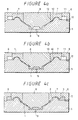
- FIGURE 4a shows a cross section of a molding metallic mold.
- the molding metallic mold comprises a first metallic mold 5, a second metallic mold 6 and a third metallic mold 7 of a core-back type.
- the first and second metallic molds 5 and 6 constitute a first cavity 8 by which the diaphragm portion 1 is molded.
- the first metallic mold 5 includes a primary gate 9 through which a molding material of the diaphragm portion 1 is injected into the first cavity 8.
- the first and third metallic molds 5 and 7 constitute a second cavity 10 by which the edge portion 2 is molded.
- the inner peripheral portion of the third metallic mold 7 forms a part of the first cavity 8 which molds the diaphragm portion 1.
- the first, second and third metallic molds 5, 6 and 7 constitute a third cavity 11 which molds the gasket portion 3.
- the second metallic mold 6 includes a secondary gate 12 through which the molding material of the edge portion 2 and the gasket portion 3 are injected into the second and third cavities 10 and 11.
- the diaphragm is molded according to the following processes.
- the diaphragm portion 1 is molded by injecting the molding material made of polypropylene into the first cavity 8 from the primary gate 9.
- the third metallic mold 7 is brought in contact with the first metallic mold 5 at a portion shown by reference numeral 13 in FIGURES 4a and 4b and the first cavity 8 is formed of the first, second and third metallic molds 5, 6 and 7 so that the first cavity 8 and the second cavity 10 are isolated from each other, thereby preventing the molding material injected into the first cavity 8 from being flowed into the second cavity 10.
- the edge portion 2 and the gasket portion 3 are molded before the molding material that was injected into the first cavity 8 to mold the diaphragm portion 1 is solidified completely.
- the third metallic mold 7 is slid backwardly within 10 seconds, for example, as shown in FIGURE 4c, and the edge portion 2 and the gasket portion 3 are molded by injecting the molding material made of saturated thermoplastic elastomer into the second and third cavities 10, 11 from the secondary gate 12. At that time, the molding material that was injected into the second cavity 10 is brought in contact with the joint portion 1a of the diaphragm portion 1 that was previously molded within the first cavity 8.
- the molding material injected into the second cavity 10 and which is in contact with the joint portion 1a of the diaphragm portion 1 is melted with the material of the diaphragm portion 1 and therefore the edge portion 2 and the diaphragm portion 1 are combined under the condition that the molding material is fully solidified. In this way, the molding operation of the diaphragm portion 1, the edge portion 2 and the gasket portion 3 is ended.
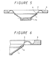
- the diaphragm taken out from the molding metallic mold includes a base portion 1c to close the opening portion of the attachment portion 1b as shown in FIGURE 5.
- the base portion 1c is cut out from the diaphragm at the position shown by a one-dot chain line in FIGURE 5 so that the diaphragm in which the diaphragm portion 1, the edge portion 2 and the gasket portion 3 are molded integrally as shown in FIGURE 3a is produced.
- the diaphragm thus molded and produced according to the present invention can solve the problem that the center of the diaphragm portion 1 and the center of the edge portion 2 are displaced from each other unlike the diaphragm produced according to the processes shown in FIGURES 1a to 1d and FIGURES 2a to 2c. Moreover, the quality of the mass-produced diaphragms can be kept constant. Further, the bonding of the edge portion, the gasket portion or the like need not be carried out and therefore the number of processes required when an electro-acoustic transducer like the speaker apparatus is assembled can be reduced, thereby the manufacturing cost being decreased.
- the third metallic mold 7 constructing a part of the first cavity 8 includes concave and convex surfaces. Then, when the diaphragm portion 1 is molded by the first cavity 8, the diaphragm portion 1 has at its portion corresponding to the concave and convex surfaces of the third metallic mold 7 formed concave and convex portions.
- the edge portion 2 is molded by the secondary molding, the molding material of the edge portion 2 is melted with the concave and convex portions of the diaphragm portion 1 and united with the diaphragm portion 1.
- an area of the joint portion 4 in which the diaphragm 1 and the edge portion 2 are melted with each other can be increased and a mechanical strength of the joint portion 4 can be improved.
- diaphragm portion 1 is made of polypropylene (PP) as described above, the present invention is not limited thereto and olefin thermoplastic resins can be widely applied to the diaphragm portion 1.
- PP polypropylene
- the material of the edge portion 2 and the gasket portion 3 is not limited to the aforesaid materials and olefin elastomer and synthetic rubber may be used.
- the present invention is not limited thereto and the following variants are also possible. That is, the edge portion 2 and the gasket portion 3 may be molded prior to the diaphragm portion 1 and the diaphragm portion 1 is molded later. Furthermore, the edge portion 2 and the gasket portion 3 may be molded by different kinds of materials according to dichromatic molding, thereby enlarging a scope in which the materials of the gasket portion 3 can be selected.
Landscapes
- Engineering & Computer Science (AREA)
- Physics & Mathematics (AREA)
- Acoustics & Sound (AREA)
- Signal Processing (AREA)
- Manufacturing & Machinery (AREA)
- Mechanical Engineering (AREA)
- Multimedia (AREA)
- Diaphragms For Electromechanical Transducers (AREA)
- Injection Moulding Of Plastics Or The Like (AREA)
Description
- The present invention relates to a method of producing a diaphragm for use with an electro-acoustic transducer and, more particularly, to a method of producing a diaphragm for use with an electro-acoustic transducer by using synthetic resin materials.
- As background to the invention a known method of producing a diaphragm for use with an electro-acoustic transducer will be described below with reference to Figures 1a to 1d and Figures 2a to 2c of the accompanying drawings. The above-mentioned diaphragm for use with an electro-acoustic transducer will be referred to hereinafter simply as "diaphragm".
- Initially, a
member 31 of substantially truncated cone configuration shown in FIGURE 1a is produced. The substantially truncated cone-shaped member 31 is produced by some suitable methods, such as sheet-making of paper and pulp, pressing of polymer film under heating or injection-molding of olefin thermoplastic resin. The substantially truncated cone-shaped member 31 is cut out at its portion shown by a one-dot chain line in FIGURE 1a to provide anouter diameter portion 32 and abottom portion 33. As a result, themember 31 is manufactured as a cone-shaped diaphragm member 34 shown in FIGURE 1b. - A
member 37 of substantially saucer configuration shown in FIGURE 1c is produced by heating and molding a material, such as cotton cloth, rubber, polyurethan foam, elastomer or the like. The substantially saucer-shaped member 37 is cut out at its positions of diameters A and B shown by one-dot chain lines in FIGURE 1c to provide an outer peripheral portion and an inner peripheral portion. - As a consequence, the substantially saucer-
shaped member 37 is manufactured as an annular-shaped edge member 38 shown in FIGURE 1d. Theedge member 38 includes anedge portion 38a of substantially U-shaped cross section. To join thediaphragm member 34 and theedge member 38 thus formed, thediaphragm member 34 is coated at its outer surface portion of the outer peripheral side with an adhesive 35 as shown in FIGURE 2a. Then, theedge member 38 is positioned on amold 41 by engaging theedge portion 38a of theedge member 38 with aprotrusion 41a of themold 41 of themolds opening portion 34a of thediaphragm member 34 is fitted onto acolumnar portion 41b by downwardly inserting thediaphragm member 34 into themold 41. Thediaphragm member 34 is positioned on themold 41. Subsequently, the mold is closed by lowering themold 40 of themolds diaphragm 34 and theedge member 38 are pressed. In this case, themolds adhesive 35 is cured under pressure produced when themolds diaphragm member 34 and theedge member 38 are joined together. - According to the method of producing a diaphragm shown in FIGURES 1a to 1d and FIGURES 2a to 2c, the
diaphragm member 34 and theedge member 38 are produced separately, and thediaphragm member 34 and theedge member 38 are manufactured as the predetermined shapes, whereafter thediaphragm member 34 and theedge member 38 are bonded together by the adhesive 35. - When however the
diaphragm member 34 is made of olefin thermoplastic resin and theedge member 38 is made of synthetic rubber or elastomer, a pre-treatment should be carried out in order to improve an adhesive property. In the pre-treatment, after thediaphragm member 34 and theedge member 38 are manufactured as the predetermined shapes, either or both of thediaphragm member 34 and theedge member 38 are coated with a primer, whereafter the adhesive 35 is coated on thediaphragm member 34 and thediaphragm member 34 and theedge member 38 are bonded together by means of the adhesive 35. Therefore, the number of manufacturing processes is increased, which unavoidably increases the manufacturing cost of the diaphragm. - When the
diaphragm member 34 and theedge member 38 are bonded together, thediaphragm member 34 and theedge member 38 should be bonded under the condition that a center of thediaphragm member 34 and a center of theedge member 38 are coincident with each other. If the center of thediaphragm member 34 and the center of theedge member 38 are displaced from each other after thediaphragm member 34 and theedge member 38 are bonded together, then the diaphragm cannot be vibrated correctly. Particularly, in the speaker apparatus of dynamic type, when the diaphragm is displaced in position, a voice coil bobbin that is attached to the diaphragm member also is displaced in position. There is then the new problem that a magnetic circuit is disturbed by the voice coil bobbin. - From an acoustic characteristic standpoint of the diaphragm, since the adhesive is interposed at the portion in which the outer peripheral edge of the diaphragm member and the inner peripheral edge of the edge member are bonded, the acoustic characteristic of the diaphragm and the quality of the diaphragm are influenced by the cured state of the adhesive and the types of the adhesives or the joined state of the diaphragm member and the edge member. As a result, the characteristic of the diaphragm thus mass-produced tends to become irregular. Therefore, it becomes impossible to obtain a diaphragm of high reliability. Moreover, when the diaphragm thus produced is used, it becomes impossible to mass-produce speaker apparatus of uniform tone quality.
- US-A-3,961,378, on which the two part form of
claim 1 is based, discloses a method of molding a diaphragm for use with an electro-acoustic transducer and having a diaphragm portion and an edge portion joined by mutually overlying portions at an outer peripheral side of the diaphragm portion. The method comprises:
a first step of molding the diaphragm portion in a first cavity; and a second step of molding in a second cavity the edge portion to the molded diaphragm portion to join the mutually overlying portions of the diaphragm portion and the edge portion. After the diaphragm portion has been pre-molded in the first step, it is interposed in position in another mold defining the second cavity to perform the second molding step. - JP-A-58,201,496 discloses a method of molding a diaphragm for use with an electro-acoustic transducer and having a diaphragm portion and an edge portion joined by mutually overlying portions at an outer peripheral side of the diaphragm portion. The method comprises: a first step of molding the diaphragm portion in a first cavity; and a second step of molding in a second cavity the edge portion to the molded diaphragm portion to join the mutually overlying portions of the diaphragm portion and the edge portion. The upper side of the first cavity for the first molding step is defined by a first die. After the first molding step, the first die is removed and replaced by a different second die defining the second cavity to perform the second molding step.
- GB-A-2,228,391 discloses a method of molding a diaphragm for use with an electrode-acoustic transducer and having a diaphragm portion and an edge portion joined edge-to-edge at an outer peripheral edge of the diaphragm portion. The method comprises: a first step of molding the edge portion in a first cavity; and a second step of molding a second cavity the diaphragm portion to the edge portion to join the edges of the diaphragm portion and the edge portion. The method is performed using a mold having a movable mold member which is movable from a first position, where the movable mold member closes off the second cavity, to a second position, where the movable mold member opens to define the second cavity. The first molding step is performed with the movable mold member in its first position and the second molding step is performed with the movable mold member in its second position.
- According to the present invention, there is provided a method of molding a diaphragm for use with an electro-acoustic transducer, said diaphragm having a diaphragm portion and an edge portion joined by mutually overlying portions at an outer peripheral side of the diaphragm portion, the method comprising:
- a first step of molding in a first cavity a first one of the diaphragm portion and the edge portion; and
- a second step of molding in a second cavity the second one of the diaphragm portion and the edge portion to the first one of said molded diaphragm portion and edge portion to join said mutually overlying portions of the diaphragm portion and the edge portion at said outer peripheral side of the diaphragm portion; characterised in that
- the method is performed using a mold having a movable mold member which is movable from a first position, where the movable mold member closes off the second cavity and overlaps the first cavity to define the part of the first cavity which molds the overlying portion of the first one of the diaphragm portion and the edge portion, to a second position, where the movable mold member defines the part of the second cavity which molds the overlying portion of the second one of the diaphragm portion and the edge portion, and
- the first molding step is performed with the movable mold member in its first position and the second molding step is performed with the movable mold member in its second position.
-
- Since the diaphragm portion and the edge portion of the diaphragm for use with an electro-acoustic transducer are integrally molded by dichromatic molding, it becomes possible to mold respective portions of the edge portion and the diaphragm portion by materials selected to provide desirable characteristics for the respective portions. Further, since the edge portion and the diaphragm portion are integrally molded together, it becomes possible to simplify the manufacturing process of the diaphragm. Also, it becomes possible to prevent the edge portion and the diaphragm portion from being detached as occurs when an adhesive for bonding the edge portion and the diaphragm portion is deteriorated.
Furthermore, since the edge portion and the diaphragm portion are molded integrally, it is possible to prevent the center of the edge portion and the center of the diaphragm portion from being displaced from each other. According to the present invention, since a substance, such as an adhesive or the like, is not interposed between the edge portion and the diaphragm portion, it is possible to avoid a frequency characteristic from being deteriorated. - The present invention will be more readily understood with reference to the accompanying drawings, wherein:
- FIGURES 1a through 1d show manufacturing processes of
a diaphragm member and an edge member of a diaphragm for an
electro-acoustic transducer according to the prior art, in which:
- FIGURE 1a is a cross-sectional view showing a cross section of a member of substantially truncated cone configuration obtained after the manufacturing process;
- FIGURE 1b is a cross-sectional view showing a cross section of a cone-shaped diaphragm member;
- FIGURE 1c is a cross-sectional view showing a cross section of a substantially saucer-shaped member; and
- FIGURE 1d is a cross-sectional view showing a cross section of an edge member;
- FIGURES 2a to 2c show manufacturing processes of a
diaphragm, in which:
- FIGURE 2a is a cross-sectional view showing the state that an adhesive is coated on the diaphragm member;
- FIGURE 2b is a cross-sectional view showing the state that the diaphragm member and the edge member are attached to the molds; and
- FIGURE 2c is a cross-sectional view showing the diaphragm obtained after the molds were bonded;
- FIGURES 3a and 3b show a diaphragm obtained with the method according to the present invention and for use with an
electro-acoustic transducer
as well as a speaker apparatus using said diaphragm,
in which:
- FIGURE 3a is a cross-sectional view showing a cross section of the diaphragm; and
- FIGURE 3b is a cross-sectional view schematically showing an arrangement of a speaker apparatus serving as the electro-acoustic transducer using the diaphragm;
- FIGURES 4a to 4c are cross-sectional views showing the
molding processes of the diaphragm according to the present
invention;
- FIGURE 4a is a cross-sectional view used to explain a schematic arrangement of a molding metallic mold;
- FIGURE 4b is a cross-sectional view showing the state that a diaphragm portion is molded; and
- FIGURE 4c is a cross-sectional view showing the state that an edge portion and a gasket portion are molded;
- FIGURE 5 is a cross-sectional view showing a diaphragm taken out from the molding metallic mold; and
- FIGURE 6 is an enlarged fragmentary cross-sectional view showing a joined portion of the diaphragm according to the present invention.
-
- A method of producing a diaphragm for use with an electro-acoustic transducer (referred to hereinafter simply as "diaphragm") according to an embodiment of the present invention will be described below with reference to the drawings.
- The embodiment of the present invention will be described hereinafter on the assumption that the diaphragm is used as the diaphragm of the speaker apparatus.
- FIGURE 3a shows a cross section of a diaphragm obtained by the method according to the embodiment of the present invention. As shown in FIGURE 3a, there is provided a cone-shaped
diaphragm portion 1. The cone-shapeddiaphragm portion 1 includes at one end thereof ajoint portion 1a whose inner surface of large diameter opening portion is joined with an edge portion, which will be described later on, and also includes on the other end thereof anattachment portion 1b of the small-diameter opening portion to which a voice coil bobbin (not shown) is attached. Thediaphragm portion 1 is formed by injection molding of polypropylene (PP) or polyolefin resin. - An
edge portion 2 includes adisplacement portion 2a of substantially U-shaped cross section and a joinedportion 2b which is joined to thejoint portion 1a of thediaphragm portion 1. Thejoint portion 1a of thediaphragm portion 1 and the joinedportion 2b of theedge portion 2 are joined together by molding which will be described later on, thereby constructing ajoint portion 4 which joins thediaphragm portion 1 and theedge portion 2. Thediaphragm portion 1 can be translated by thedisplacement portion 2a of theedge portion 2 in the upper and lower direction in FIGURE 3a. - A
gasket portion 3 is integrally provided on the outer peripheral side of theedge portion 2 through theedge portion 2 and a thin portion. Thegasket portion 3 is attached to the upper surface of the frame of the speaker apparatus (not shown). - The
edge portion 2 and thegasket portion 3 are integrally molded together by using saturated thermoplastic elastomer. The saturated thermoplastic elastomer can be molded by injection molding and extrusion molding by a standard plastic molding machine and can be melted with the material of thediaphragm portion 1, i.e., polypropylene satisfactorily. - An arrangement of a speaker apparatus using the diaphragm thus arranged will be described below with reference to FIGURE 3b.
- As shown in FIGURE 3b, a
voice coil bobbin 20 is joined to theattachment portion 1b of thediaphragm portion 1. Thevoice coil bobbin 20 is inserted into a gap of amagnetic circuit 21. Themagnetic circuit 21 includes apermanent magnet 21a, ayoke 21b having acenter pole 21c and atop plate 21d. Thetop plate 21d is disposed in an opposing relation to avoice coil 20a wound around thevoice coil bobbin 20. Thevoice coil 20a is supplied with an input signal through a litz wire (not shown). Thepermanent magnet 21a is disposed between theyoke 21b and thetop plate 21d. Aframe 22 is attached on thetop plate 21d, and theframe 22 has on its upper surface portion bonded thegasket portion 3 by an adhesive 24. Adamper 23 is disposed between (i) theframe 22 and (ii) either the joined portion of theattachment portion 1b of thediaphragm portion 1 and thevoice coil bobbin 20 or a nearby position. Thedamper 23 and thedisplacement portion 2a of theedge portion 2 support the diaphragm such that the diaphragm can be slid in the upper and lower direction shown in FIGURE 3b. As a consequence, the diaphragm is vibrated by a driving force generated by themagnetic circuit 21 and thevoice coil 20a of thevoice coil bobbin 20 in the upper and lower direction shown in FIGURE 3b. - A method of molding the above-mentioned diaphragm will be described with reference to FIGURES 4a to 4c.
- FIGURE 4a shows a cross section of a molding metallic mold. As shown in FIGURE 4a, the molding metallic mold comprises a first
metallic mold 5, a secondmetallic mold 6 and a thirdmetallic mold 7 of a core-back type. The first and secondmetallic molds first cavity 8 by which thediaphragm portion 1 is molded. The firstmetallic mold 5 includes aprimary gate 9 through which a molding material of thediaphragm portion 1 is injected into thefirst cavity 8. - The first and third
metallic molds second cavity 10 by which theedge portion 2 is molded. The inner peripheral portion of the thirdmetallic mold 7 forms a part of thefirst cavity 8 which molds thediaphragm portion 1. The first, second and thirdmetallic molds third cavity 11 which molds thegasket portion 3. The secondmetallic mold 6 includes asecondary gate 12 through which the molding material of theedge portion 2 and thegasket portion 3 are injected into the second andthird cavities - The diaphragm is molded according to the following processes.
- Initially, the
diaphragm portion 1 is molded by injecting the molding material made of polypropylene into thefirst cavity 8 from theprimary gate 9. At that time, the thirdmetallic mold 7 is brought in contact with the firstmetallic mold 5 at a portion shown byreference numeral 13 in FIGURES 4a and 4b and thefirst cavity 8 is formed of the first, second and thirdmetallic molds first cavity 8 and thesecond cavity 10 are isolated from each other, thereby preventing the molding material injected into thefirst cavity 8 from being flowed into thesecond cavity 10. - After the
diaphragm portion 1 is molded, theedge portion 2 and thegasket portion 3 are molded before the molding material that was injected into thefirst cavity 8 to mold thediaphragm portion 1 is solidified completely. Specifically, after thediaphragm portion 1 is molded, the thirdmetallic mold 7 is slid backwardly within 10 seconds, for example, as shown in FIGURE 4c, and theedge portion 2 and thegasket portion 3 are molded by injecting the molding material made of saturated thermoplastic elastomer into the second andthird cavities secondary gate 12. At that time, the molding material that was injected into thesecond cavity 10 is brought in contact with thejoint portion 1a of thediaphragm portion 1 that was previously molded within thefirst cavity 8. The molding material injected into thesecond cavity 10 and which is in contact with thejoint portion 1a of thediaphragm portion 1 is melted with the material of thediaphragm portion 1 and therefore theedge portion 2 and thediaphragm portion 1 are combined under the condition that the molding material is fully solidified. In this way, the molding operation of thediaphragm portion 1, theedge portion 2 and thegasket portion 3 is ended. - After the
diaphragm portion 1, theedge portion 2 and thegasket portion 3 are solidified since theedge portion 2 and thegasket portion 3 were molded, the molding metallic mold is opened and the diaphragm is detached from the molding metallic mold. The diaphragm taken out from the molding metallic mold includes abase portion 1c to close the opening portion of theattachment portion 1b as shown in FIGURE 5. Thebase portion 1c is cut out from the diaphragm at the position shown by a one-dot chain line in FIGURE 5 so that the diaphragm in which thediaphragm portion 1, theedge portion 2 and thegasket portion 3 are molded integrally as shown in FIGURE 3a is produced. - The diaphragm thus molded and produced according to the present invention can solve the problem that the center of the
diaphragm portion 1 and the center of theedge portion 2 are displaced from each other unlike the diaphragm produced according to the processes shown in FIGURES 1a to 1d and FIGURES 2a to 2c. Moreover, the quality of the mass-produced diaphragms can be kept constant. Further, the bonding of the edge portion, the gasket portion or the like need not be carried out and therefore the number of processes required when an electro-acoustic transducer like the speaker apparatus is assembled can be reduced, thereby the manufacturing cost being decreased. - In the diaphragm according to the present invention, the third
metallic mold 7 constructing a part of thefirst cavity 8 includes concave and convex surfaces. Then, when thediaphragm portion 1 is molded by thefirst cavity 8, thediaphragm portion 1 has at its portion corresponding to the concave and convex surfaces of the thirdmetallic mold 7 formed concave and convex portions. When theedge portion 2 is molded by the secondary molding, the molding material of theedge portion 2 is melted with the concave and convex portions of thediaphragm portion 1 and united with thediaphragm portion 1. Thus, as shown in FIGURE 6, an area of thejoint portion 4 in which thediaphragm 1 and theedge portion 2 are melted with each other can be increased and a mechanical strength of thejoint portion 4 can be improved. - While the
diaphragm portion 1 is made of polypropylene (PP) as described above, the present invention is not limited thereto and olefin thermoplastic resins can be widely applied to thediaphragm portion 1. - The material of the
edge portion 2 and thegasket portion 3 is not limited to the aforesaid materials and olefin elastomer and synthetic rubber may be used. - Further, while the
diaphragm portion 1 is molded prior to theedge portion 2 and thegasket portion 3 according to the molding method of the present invention, the present invention is not limited thereto and the following variants are also possible. That is, theedge portion 2 and thegasket portion 3 may be molded prior to thediaphragm portion 1 and thediaphragm portion 1 is molded later. Furthermore, theedge portion 2 and thegasket portion 3 may be molded by different kinds of materials according to dichromatic molding, thereby enlarging a scope in which the materials of thegasket portion 3 can be selected. - Having described a preferred embodiment of the invention with reference to the accompanying drawings, it is to be understood that the invention is not limited thereto and that various changes and modifications could be effected therein by one skilled in the art without departing from the scope of the invention as defined in the appended claims.
Claims (5)
- A method of molding a diaphragm for use with an electro-acoustic transducer, said diaphragm having a diaphragm portion (1) and an edge portion (2) joined by mutually overlying portions (1a, 2b) at an outer peripheral side of the diaphragm portion (1), the method comprising:characterised in thata first step of molding in a first cavity (8) a first one of the diaphragm portion (1) and the edge portion (2); anda second step of molding in a second cavity (10) the second one of the diaphragm portion (1) and the edge portion (2) to the first one of said molded diaphragm portion (1) and edge portion (2) to join said mutually overlying portions (1a, 2b) of the diaphragm portion (1) and the edge portion (2) at said outer peripheral side of the diaphragm portion (1);the method is performed using a mold (5, 6, 7) having a movable mold member (7) which is movable from a first position, where the movable mold member (7) closes off the second cavity (10) and overlaps the first cavity (8) to define the part of the first cavity (8) which molds the overlying portion (1a; 2b) of the first one of the diaphragm portion (1) and the edge portion (2), to a second position, where the movable mold member (7) defines the part of the second cavity (10) which molds the overlying portion (2b; 1a) of the second one of the diaphragm portion (1) and the edge portion (2), andthe first molding step is performed with the movable mold member (7) in its first position and the second molding step is performed with the movable mold member in its second position.
- A method according to claim 1, wherein the second molding step is performed before the molding material injected into the first cavity (8) in the first molding step has solidified completely.
- A method according to claim 1 or 2, wherein a supporting portion (3) for supporting said edge portion is molded together with the edge portion (2) by the one of the first or second molding steps in which the edge portion (2) is molded.
- A method according to claim 3, wherein the supporting portion is a gasket (3).
- A method according to any one of the preceding claims, wherein the first one of the diaphragm portion (1) and the edge portion (2) is the diaphragm portion (1) and the second one of the diaphragm portion (1) and the edge portion (2) is the edge portion (2).
Applications Claiming Priority (3)
| Application Number | Priority Date | Filing Date | Title |
|---|---|---|---|
| JP5157420A JPH0715793A (en) | 1993-06-28 | 1993-06-28 | Speaker diaphragm and method of forming the same |
| JP157420/93 | 1993-06-28 | ||
| JP15742093 | 1993-06-28 |
Publications (2)
| Publication Number | Publication Date |
|---|---|
| EP0632674A1 EP0632674A1 (en) | 1995-01-04 |
| EP0632674B1 true EP0632674B1 (en) | 2001-08-22 |
Family
ID=15649247
Family Applications (1)
| Application Number | Title | Priority Date | Filing Date |
|---|---|---|---|
| EP94304667A Expired - Lifetime EP0632674B1 (en) | 1993-06-28 | 1994-06-27 | Method of producing a diaphragm for use with an electro-acoustic transducer |
Country Status (7)
| Country | Link |
|---|---|
| US (1) | US5521886A (en) |
| EP (1) | EP0632674B1 (en) |
| JP (1) | JPH0715793A (en) |
| KR (1) | KR100339678B1 (en) |
| CN (1) | CN1071986C (en) |
| CA (1) | CA2126526C (en) |
| DE (1) | DE69428009T2 (en) |
Cited By (1)
| Publication number | Priority date | Publication date | Assignee | Title |
|---|---|---|---|---|
| EP4520783A4 (en) * | 2022-05-16 | 2025-07-16 | Lg Electronics Inc | CELLULOSE COMPOSITE PELLETS, MEMBRANE AND ACOUSTIC SYSTEM |
Families Citing this family (60)
| Publication number | Priority date | Publication date | Assignee | Title |
|---|---|---|---|---|
| JP3158023B2 (en) * | 1995-10-03 | 2001-04-23 | フオスター電機株式会社 | Method for manufacturing edge for speaker |
| IT1281924B1 (en) * | 1995-12-22 | 1998-03-03 | Sipe Srl | METHOD FOR MAKING AND APPLYING THE SUSPENSION RING EDGE OF THE SPEAKER MEMBRANES |
| AT403751B (en) * | 1996-06-19 | 1998-05-25 | Akg Akustische Kino Geraete | METHOD FOR PRODUCING A MEMBRANE FOR AN ELECTROACOUSTIC TRANSDUCER |
| US6563930B1 (en) * | 1996-12-04 | 2003-05-13 | Murata Manufacturing Co., Ltd. | Speaker |
| US6332508B1 (en) | 1997-03-12 | 2001-12-25 | Siegfried Schriever | Loudspeaker and method for producing the same |
| US5894264A (en) * | 1997-07-18 | 1999-04-13 | Caterpillar Inc. | Apparatus for generating an audible tone |
| US5953436A (en) * | 1997-07-18 | 1999-09-14 | Caterpillar Inc. | Apparatus for generating an audible tone |
| JP3299709B2 (en) * | 1998-01-09 | 2002-07-08 | 松下電器産業株式会社 | Chloroprene synthetic rubber adhesive composition and method for producing speaker |
| GB2326373B (en) * | 1998-08-20 | 2000-01-19 | Kurt Mueller | Speaker cone |
| JP3508834B2 (en) * | 1999-04-22 | 2004-03-22 | 株式会社ケンウッド | Speaker diaphragm |
| JP2001036988A (en) * | 1999-07-21 | 2001-02-09 | Mitsubishi Electric Corp | Speaker device |
| JP4484312B2 (en) * | 2000-05-01 | 2010-06-16 | 株式会社デンソー | Resin molded product consisting of hard molded resin part and soft member part |
| WO2003009640A2 (en) * | 2001-07-19 | 2003-01-30 | Koninklijke Philips Electronics N.V. | Electroacoustic transducer comprising a membrane with an improved pleats area |
| GB0219106D0 (en) * | 2002-08-16 | 2002-09-25 | Kh Technology Corp | Improvements in loudspeakers |
| US7548632B2 (en) * | 2004-03-31 | 2009-06-16 | Panasonic Corporation | Speaker, module using the same, electronic equipment and device, and speaker producing method |
| JP4414809B2 (en) * | 2004-04-26 | 2010-02-10 | パイオニア株式会社 | Method for manufacturing diaphragm for electroacoustic transducer |
| JP4563112B2 (en) * | 2004-08-25 | 2010-10-13 | フォスター電機株式会社 | Method for manufacturing edge for electroacoustic transducer and edge produced thereby |
| WO2006073604A1 (en) * | 2004-11-22 | 2006-07-13 | Harman International Industries, Incorporated | Loudspeaker plastic cone body |
| JP2006144200A (en) | 2004-11-24 | 2006-06-08 | Brother Ind Ltd | Embroidery frame |
| JP2006287830A (en) * | 2005-04-05 | 2006-10-19 | Foster Electric Co Ltd | Method for manufacturing diaphragm for electroacoustic transducer and diaphragm for electroacoustic transducer |
| ATE479292T1 (en) * | 2005-05-25 | 2010-09-15 | Nxp Bv | IMPROVED MEMBRANE FOR AN ELECTROACOUSTIC TRANSDUCER |
| GB2427378A (en) * | 2005-06-17 | 2006-12-27 | Metflex Prec Mouldings Ltd | Moulding speaker cone constructions |
| JP4658705B2 (en) * | 2005-06-24 | 2011-03-23 | 岐阜プラスチック工業株式会社 | Method for molding synthetic resin injection molded product and injection mold apparatus |
| JP4553377B2 (en) * | 2005-08-23 | 2010-09-29 | パイオニア株式会社 | Method for manufacturing diaphragm for electroacoustic transducer, and diaphragm for electroacoustic transducer |
| US8077903B2 (en) * | 2005-10-25 | 2011-12-13 | Mckenzie Mark Douglas | Method and apparatus for controlling material vibration modes in polymer and paper high performance speaker diaphragms |
| JP4611887B2 (en) * | 2005-12-26 | 2011-01-12 | パイオニア株式会社 | Manufacturing method of speaker edge |
| CN1992996B (en) * | 2005-12-30 | 2012-02-29 | 丁轶 | Detachable supporting structure for loudspeaker diaphragm |
| JP4569477B2 (en) | 2006-01-17 | 2010-10-27 | パナソニック株式会社 | Speaker |
| US20080118090A1 (en) * | 2006-11-22 | 2008-05-22 | Daniel John Sheehan | Surround attachment |
| CN101855670A (en) | 2007-09-13 | 2010-10-06 | 哈曼国际工业有限公司 | Loudspeaker cone shell |
| US8516681B2 (en) * | 2008-10-27 | 2013-08-27 | Panasonic Corporation | Loud speaker manufacturing method |
| JP2010263281A (en) * | 2009-04-30 | 2010-11-18 | Panasonic Corp | Speaker diaphragm and speaker using the same |
| JP5471435B2 (en) * | 2009-12-28 | 2014-04-16 | パナソニック株式会社 | Speaker diaphragm, speaker using the same, and portable terminal device |
| JP2011211572A (en) * | 2010-03-30 | 2011-10-20 | Panasonic Corp | Diaphragm for loudspeaker, and loudspeaker using the same |
| WO2011122673A1 (en) * | 2010-03-30 | 2011-10-06 | 株式会社ブリヂストン | Method for manufacturing acoustic diaphragm |
| JP2011211573A (en) * | 2010-03-30 | 2011-10-20 | Panasonic Corp | Diaphragm for loudspeaker, and loudspeaker using the same |
| US8452037B2 (en) | 2010-05-05 | 2013-05-28 | Apple Inc. | Speaker clip |
| JP5565573B2 (en) * | 2010-06-25 | 2014-08-06 | オンキヨー株式会社 | Speaker diaphragm and speaker equipped with the speaker diaphragm |
| WO2012155726A1 (en) * | 2011-05-19 | 2012-11-22 | Huang Xinmin | Vibrating plate device of electromagnetic vibrator and manufacture method thereof |
| US8989428B2 (en) | 2011-08-31 | 2015-03-24 | Apple Inc. | Acoustic systems in electronic devices |
| US9820033B2 (en) | 2012-09-28 | 2017-11-14 | Apple Inc. | Speaker assembly |
| US9357299B2 (en) | 2012-11-16 | 2016-05-31 | Apple Inc. | Active protection for acoustic device |
| US9788122B2 (en) * | 2012-12-26 | 2017-10-10 | Xin Min HUANG | Vibrating panel device for electromagnetic vibrator and manufacture method thereof |
| US20150078611A1 (en) * | 2013-09-16 | 2015-03-19 | Apple Inc. | Joint speaker surround and gasket, and methods of manufacture thereof |
| US9451354B2 (en) | 2014-05-12 | 2016-09-20 | Apple Inc. | Liquid expulsion from an orifice |
| FR3035295B1 (en) * | 2015-04-15 | 2017-04-21 | Focal Jmlab | SUSPENSION DEVICE FOR SPEAKER, METHOD OF MANUFACTURE AND SPEAKER THEREFOR |
| US9900698B2 (en) | 2015-06-30 | 2018-02-20 | Apple Inc. | Graphene composite acoustic diaphragm |
| CN105554676B (en) * | 2015-11-20 | 2019-04-23 | 广东方振新材料精密组件有限公司 | A kind of horn vibration film and its moulding process |
| CN106973354B (en) * | 2017-04-12 | 2018-11-30 | 歌尔股份有限公司 | The processing method of acoustical device |
| US11307661B2 (en) | 2017-09-25 | 2022-04-19 | Apple Inc. | Electronic device with actuators for producing haptic and audio output along a device housing |
| US10757491B1 (en) | 2018-06-11 | 2020-08-25 | Apple Inc. | Wearable interactive audio device |
| US10873798B1 (en) | 2018-06-11 | 2020-12-22 | Apple Inc. | Detecting through-body inputs at a wearable audio device |
| US11334032B2 (en) | 2018-08-30 | 2022-05-17 | Apple Inc. | Electronic watch with barometric vent |
| US11561144B1 (en) | 2018-09-27 | 2023-01-24 | Apple Inc. | Wearable electronic device with fluid-based pressure sensing |
| CN110049425A (en) * | 2019-03-13 | 2019-07-23 | 东莞涌韵音膜有限公司 | Forming process of moving coil speaker unit with micro-diaphragm |
| CN113994345A (en) | 2019-04-17 | 2022-01-28 | 苹果公司 | Wireless locatable tag |
| JP2021164045A (en) * | 2020-03-31 | 2021-10-11 | パナソニックIpマネジメント株式会社 | Speaker diaphragm, speaker, speaker diaphragm manufacturing method, electronic device, and mobile device |
| US12256032B2 (en) | 2021-03-02 | 2025-03-18 | Apple Inc. | Handheld electronic device |
| CN113547694B (en) * | 2021-06-15 | 2023-09-08 | 江苏新泉模具有限公司 | In-mold decoration process for inverted packaging of automobile interior trim product |
| CN116100712A (en) * | 2022-12-08 | 2023-05-12 | 中国船舶重工集团公司第七一五研究所 | A high-efficiency and low-loss metal cover plate vulcanization mold and method |
Family Cites Families (8)
| Publication number | Priority date | Publication date | Assignee | Title |
|---|---|---|---|---|
| US3961378A (en) * | 1973-01-19 | 1976-06-08 | White Stanley F | Cone construction for loudspeaker |
| DE7925593U1 (en) * | 1979-09-10 | 1980-02-28 | Deutsche Semperit Gmbh, 8000 Muenchen | SPEAKER MEMBRANE |
| JPS58201496A (en) * | 1982-05-20 | 1983-11-24 | Sanyo Electric Co Ltd | Manufacture of diaphragm for speaker |
| JPH02209215A (en) * | 1989-02-10 | 1990-08-20 | Pioneer Electron Corp | Die device of diaphragm for speaker |
| JPH02260799A (en) * | 1989-03-30 | 1990-10-23 | Pioneer Electron Corp | Speaker and its manufacture |
| CA2066262C (en) * | 1990-05-26 | 1996-02-27 | Shinichiro Kitanishi | Piezoelectric sound generator and method of its manufacture |
| EP0492914A3 (en) * | 1990-12-20 | 1992-10-21 | Leach, Patrick Arthur | Loudspeaker cone and surround assembly |
| EP0552040B1 (en) * | 1992-01-15 | 1996-01-03 | Patrick Arthur Leach | Method and apparatus for making a loudspeaker cone and surround assembly |
-
1993
- 1993-06-28 JP JP5157420A patent/JPH0715793A/en active Pending
-
1994
- 1994-06-22 CA CA002126526A patent/CA2126526C/en not_active Expired - Fee Related
- 1994-06-27 CN CN94108926A patent/CN1071986C/en not_active Expired - Fee Related
- 1994-06-27 EP EP94304667A patent/EP0632674B1/en not_active Expired - Lifetime
- 1994-06-27 DE DE69428009T patent/DE69428009T2/en not_active Expired - Fee Related
- 1994-06-27 KR KR1019940014787A patent/KR100339678B1/en not_active Expired - Fee Related
- 1994-06-28 US US08/266,981 patent/US5521886A/en not_active Expired - Fee Related
Cited By (1)
| Publication number | Priority date | Publication date | Assignee | Title |
|---|---|---|---|---|
| EP4520783A4 (en) * | 2022-05-16 | 2025-07-16 | Lg Electronics Inc | CELLULOSE COMPOSITE PELLETS, MEMBRANE AND ACOUSTIC SYSTEM |
Also Published As
| Publication number | Publication date |
|---|---|
| JPH0715793A (en) | 1995-01-17 |
| US5521886A (en) | 1996-05-28 |
| DE69428009T2 (en) | 2002-04-18 |
| DE69428009D1 (en) | 2001-09-27 |
| CN1071986C (en) | 2001-09-26 |
| CA2126526C (en) | 2002-10-29 |
| KR100339678B1 (en) | 2002-11-16 |
| CN1105500A (en) | 1995-07-19 |
| EP0632674A1 (en) | 1995-01-04 |
| CA2126526A1 (en) | 1994-12-29 |
Similar Documents
| Publication | Publication Date | Title |
|---|---|---|
| US5521886A (en) | Diaphragm for use with an electro-acoustic transducer and method of producing the same | |
| US6757404B2 (en) | Loud speaker, diaphragm and process for making the diaphragm | |
| US6171534B1 (en) | Method of making a speaker cone and surround assembly | |
| JP4148211B2 (en) | Speaker device | |
| JP2002218590A (en) | Micro speaker magnetic circuit | |
| JP3246183B2 (en) | Vibration member for speaker and method of manufacturing the same | |
| EP0492914A2 (en) | Loudspeaker cone and surround assembly | |
| JP5309811B2 (en) | Speaker diaphragm, speaker using the same, and method for manufacturing speaker diaphragm | |
| JP3972303B2 (en) | Mold for forming diaphragm and method for manufacturing diaphragm | |
| JP3044831B2 (en) | Speaker manufacturing method | |
| JP2010287989A (en) | Member for loudspeaker and method of manufacturing the same | |
| GB2322589A (en) | Moulding loudspeaker cone surround assembly | |
| JPH10210593A (en) | Diaphragm for speaker and its manufacture | |
| JP2004179792A (en) | Speaker | |
| JP2838721B2 (en) | Speaker | |
| JPH01200900A (en) | Speaker diaphragm and its manufacture | |
| KR100635257B1 (en) | Method for manufacturing vibrating body of electro-acoustic converter, molding apparatus therefor, vibrating body and electro-acoustic converting device produced by the same | |
| WO2022102260A1 (en) | Speaker and method of producing the same | |
| KR200378486Y1 (en) | One body plastic apparatus of edge and cone paper of speaker for audio | |
| KR100676399B1 (en) | speaker | |
| GB2251204A (en) | Loudspeakers | |
| JPH06270196A (en) | Integrally molding method for cone and edge for speaker | |
| JP2002354594A (en) | Method for manufacturing diaphragm for speaker and diaphragm for speaker | |
| JPH09109155A (en) | Manufacture of engaging cover and mold used therefor | |
| JPH07111689A (en) | Speaker gasket |
Legal Events
| Date | Code | Title | Description |
|---|---|---|---|
| PUAI | Public reference made under article 153(3) epc to a published international application that has entered the european phase |
Free format text: ORIGINAL CODE: 0009012 |
|
| AK | Designated contracting states |
Kind code of ref document: A1 Designated state(s): DE FR GB |
|
| 17P | Request for examination filed |
Effective date: 19950608 |
|
| 17Q | First examination report despatched |
Effective date: 19981019 |
|
| RTI1 | Title (correction) |
Free format text: METHOD OF PRODUCING A DIAPHRAGM FOR USE WITH AN ELECTRO-ACOUSTIC TRANSDUCER |
|
| RTI1 | Title (correction) |
Free format text: METHOD OF PRODUCING A DIAPHRAGM FOR USE WITH AN ELECTRO-ACOUSTIC TRANSDUCER |
|
| GRAG | Despatch of communication of intention to grant |
Free format text: ORIGINAL CODE: EPIDOS AGRA |
|
| RTI1 | Title (correction) |
Free format text: METHOD OF PRODUCING A DIAPHRAGM FOR USE WITH AN ELECTRO-ACOUSTIC TRANSDUCER |
|
| GRAG | Despatch of communication of intention to grant |
Free format text: ORIGINAL CODE: EPIDOS AGRA |
|
| GRAH | Despatch of communication of intention to grant a patent |
Free format text: ORIGINAL CODE: EPIDOS IGRA |
|
| GRAH | Despatch of communication of intention to grant a patent |
Free format text: ORIGINAL CODE: EPIDOS IGRA |
|
| GRAA | (expected) grant |
Free format text: ORIGINAL CODE: 0009210 |
|
| RAP1 | Party data changed (applicant data changed or rights of an application transferred) |
Owner name: TANAKA KOGYO CORPORATION LIMITED Owner name: SONY CORPORATION |
|
| AK | Designated contracting states |
Kind code of ref document: B1 Designated state(s): DE FR GB |
|
| REF | Corresponds to: |
Ref document number: 69428009 Country of ref document: DE Date of ref document: 20010927 |
|
| REG | Reference to a national code |
Ref country code: GB Ref legal event code: IF02 |
|
| ET | Fr: translation filed | ||
| PLBE | No opposition filed within time limit |
Free format text: ORIGINAL CODE: 0009261 |
|
| STAA | Information on the status of an ep patent application or granted ep patent |
Free format text: STATUS: NO OPPOSITION FILED WITHIN TIME LIMIT |
|
| 26N | No opposition filed | ||
| PGFP | Annual fee paid to national office [announced via postgrant information from national office to epo] |
Ref country code: DE Payment date: 20030710 Year of fee payment: 10 |
|
| PG25 | Lapsed in a contracting state [announced via postgrant information from national office to epo] |
Ref country code: DE Free format text: LAPSE BECAUSE OF NON-PAYMENT OF DUE FEES Effective date: 20050101 |
|
| PGFP | Annual fee paid to national office [announced via postgrant information from national office to epo] |
Ref country code: FR Payment date: 20050608 Year of fee payment: 12 |
|
| PGFP | Annual fee paid to national office [announced via postgrant information from national office to epo] |
Ref country code: GB Payment date: 20050622 Year of fee payment: 12 |
|
| PG25 | Lapsed in a contracting state [announced via postgrant information from national office to epo] |
Ref country code: GB Free format text: LAPSE BECAUSE OF NON-PAYMENT OF DUE FEES Effective date: 20060627 |
|
| GBPC | Gb: european patent ceased through non-payment of renewal fee |
Effective date: 20060627 |
|
| REG | Reference to a national code |
Ref country code: FR Ref legal event code: ST Effective date: 20070228 |
|
| PG25 | Lapsed in a contracting state [announced via postgrant information from national office to epo] |
Ref country code: FR Free format text: LAPSE BECAUSE OF NON-PAYMENT OF DUE FEES Effective date: 20060630 |