EP0631843B1 - Two plane oscillating sander - Google Patents
Two plane oscillating sander Download PDFInfo
- Publication number
- EP0631843B1 EP0631843B1 EP19940304807 EP94304807A EP0631843B1 EP 0631843 B1 EP0631843 B1 EP 0631843B1 EP 19940304807 EP19940304807 EP 19940304807 EP 94304807 A EP94304807 A EP 94304807A EP 0631843 B1 EP0631843 B1 EP 0631843B1
- Authority
- EP
- European Patent Office
- Prior art keywords
- sanding
- head
- sander
- axis
- sander according
- Prior art date
- Legal status (The legal status is an assumption and is not a legal conclusion. Google has not performed a legal analysis and makes no representation as to the accuracy of the status listed.)
- Expired - Lifetime
Links
- 239000004576 sand Substances 0.000 description 4
- 239000003082 abrasive agent Substances 0.000 description 3
- 230000003247 decreasing effect Effects 0.000 description 1
- 230000004048 modification Effects 0.000 description 1
- 238000012986 modification Methods 0.000 description 1
- 230000010355 oscillation Effects 0.000 description 1
- 230000003534 oscillatory effect Effects 0.000 description 1
Images
Classifications
-
- B—PERFORMING OPERATIONS; TRANSPORTING
- B24—GRINDING; POLISHING
- B24B—MACHINES, DEVICES, OR PROCESSES FOR GRINDING OR POLISHING; DRESSING OR CONDITIONING OF ABRADING SURFACES; FEEDING OF GRINDING, POLISHING, OR LAPPING AGENTS
- B24B23/00—Portable grinding machines, e.g. hand-guided; Accessories therefor
- B24B23/04—Portable grinding machines, e.g. hand-guided; Accessories therefor with oscillating grinding tools; Accessories therefor
Definitions
- the present invention relates to a portable oscillating sander of the type including a housing and a sanding head adapted to be attached thereto so as to undergo oscillating relative rotation about a predetermined axis.
- a sanding head according to the preamble of claim 1 and a portable oscillating sander according to the preamble of claim 2 are known, for example, from EP-A-0 333 933.
- sanders of the above type include a triangular sanding head, the lower surface of which is covered with abrasive material.
- the triangular shape of head enables the sander to be used for sanding into a corner.
- the sanding heads are detachable from the sander to enable their replacement either when they are worn out or when a coarser or finer abrasive is required.
- the sanding heads taper from a largest cross-section corresponding to the sanding surface through decreasing cross-sections until the upper surface of the sanding head is reached. This enables the sanding surface to reach right into a corner, for example, unimpeded by the impingement of other regions of the sanding head on the workpiece.
- Such sanders are useful for sanding in one plane only.
- the present invention provides a sanding head for a portable oscillating sander, adapted to be attached thereto so as to undergo oscillating relative rotation about a predetermined axis of the head, the sanding head including a substantially flat sanding surface substantially normal to the said axis and a second sanding surface formed by rotation of a line about an axis substantially coincident with the said predetermined axis.
- the invention also provides a portable oscillating sander including a housing and a sanding head adapted to be attached thereto so as to undergo oscillating relative rotation about a predetermined axis, the sanding head including a substantially flat sanding surface substantially normal to the said axis and a second sanding surface formed by rotation of a line about an axis substantially coincident with the said predetermined axis.
- the substantially flat sanding surface is the equivalent of the sanding surface discussed above with reference to existing portable sanders.
- the second sanding surface is preferably substantially part-conical, and is useful for sanding in a plane lying at an angle to the substantially flat sanding surface, since it is substantially concentric with the oscillating motion of the head.
- the motion of a point on the substantially part-conical sanding surface is, at any instant in time, tangential to the surface and does not possess any component normal to the surface.
- This second sanding surface provides the portable sander according to the invention with a unique capability for sanding in two planes.
- the substantially part-conical sanding surface should be substantially part-cylindrical.
- the substantially flat sanding surface meet the second sanding surface at a substantially part-circular edge.
- the substantially flat sanding surface terminate at a vertex.
- the vertex should lie opposite the substantially part-circular edge. This will enable the sander to be used for sanding into a corner.
- the vertex makes an angle of no more than 90 degrees.
- the head should be substantially symmetric about the plane containing the said predetermined axis and the vertex.
- the substantially flat surface should circumscribe the remainder of the head when viewed along the said predetermined axis.
- the sanding head may be adapted to be attached to the portable oscillating sander in any one of a plurality of angular orientations about the said predetermined axis.
- the sander includes a drive spindle to which the sanding head is adapted to be attached
- this may be achieved by providing the drive spindle with a regular polygonal drive pin which forms a snap-fit in a corresponding bore in the sanding head, or vice versa .
- Figure 1 illustrates a sander 10 comprising a housing 12 and an oscillating head 14.
- the head 14 is driven by a drive mechanism (not shown) and oscillates about an axis 16 in an angular movement.
- the head 14 has a lower, substantially flat sanding surface 18 which is covered with abrasive material and can sand surfaces in a plane substantially perpendicular to the axis 16.
- the sanding head is of a generally tear-drop shape, terminating at one end in a vertex 20 and being provided at its other end with a part-cylindrical surface 26, which is centred on the axis 16.
- Two further vertices 22, 24 are provided, one on each side of the part-cylindrical surface 26. These further vertices 22, 24 can also be employed for sanding into corners using the flat sanding surface 18.
- the part-cylindrical sanding surface 26 is centred on the axis 16 of rotation of the sanding head, it too can be used as a sanding surface and, as is illustrated in Figure 2, this surface is also covered with abrasive material.
- abrasive material During oscillatory motion of the sanding head, there is no movement of any part of the part-cylindrical sanding surface 26 otherwise than tangential to the surface and this enables the surface 26 to be employed for sanding in a plane perpendicular to the flat sanding surface 18.
- the portable oscillating sander according to the invention possesses the unique capability of sanding in two planes.
- the sander can be used to sand simultaneously in two planes and into the corner defined by the two planes, for example where a right-angled corner is required, since the two sanding surfaces 18, 26 meet one another at a part-circular edge 25.
- the sanding head 14 is symmetrical about a plane 27 containing the axis of rotation 16 and the vertex 20.
- the centre of mass of the sanding head lies on the axis of rotation 16. This symmetry prevents excessive vibration of the sander.
- the vertex 20 makes an angle of less than 90 degrees, which enables the flat sanding surface 18 to be used for sanding into a right-angled corner.
- no part of the sanding head 14 projects beyond the extremities of the flat sanding surface 18 when the head is viewed from directly below, i.e. along the axis of rotation 16.
- Figure 4 illustrates a drive mechanism suitable for use in the sander 10.
- the mechanism includes a drive shaft 30 which is rotated about its longitudinal axis by a motor (not shown).
- An eccentric pin 32 on the end of the drive shaft 30, is received in rotational engagement in a bore 35 of an intermediate member 34.
- the intermediate member 34 has a pair of part-cylindrical side surfaces 37, which are engaged within a part-cylindrical recess 38 of a yoke 36 which is free only to rotate about an axis 16.
- the intermediate member 34 oscillates both up and down and from side to side as the shaft 30 rotates. To a small extent, owing to the oscillation of the yoke 36, the intermediate member also oscillates longitudinally along the eccentric pin 32. The movement of the intermediate member 34 is translated into oscillating rotation of the yoke 36 about the axis 16.
- the yoke 36 is provided with a drive spindle 41 having a square drive pin 40, centred on the axis 16 and which is a snap-fit in a corresponding bore 42 of the head 14, as illustrated in figure 2. Accordingly, the head 14 can be pulled off the drive pin 40 and reconnected in different angular orientations as suits the user.
Landscapes
- Engineering & Computer Science (AREA)
- Mechanical Engineering (AREA)
- Finish Polishing, Edge Sharpening, And Grinding By Specific Grinding Devices (AREA)
- Grinding-Machine Dressing And Accessory Apparatuses (AREA)
Description
- The present invention relates to a portable oscillating sander of the type including a housing and a sanding head adapted to be attached thereto so as to undergo oscillating relative rotation about a predetermined axis. A sanding head according to the preamble of claim 1 and a portable oscillating sander according to the preamble of claim 2 are known, for example, from EP-A-0 333 933.
- Typically, sanders of the above type include a triangular sanding head, the lower surface of which is covered with abrasive material. The triangular shape of head enables the sander to be used for sanding into a corner. The sanding heads are detachable from the sander to enable their replacement either when they are worn out or when a coarser or finer abrasive is required.
- Typically, the sanding heads taper from a largest cross-section corresponding to the sanding surface through decreasing cross-sections until the upper surface of the sanding head is reached. This enables the sanding surface to reach right into a corner, for example, unimpeded by the impingement of other regions of the sanding head on the workpiece. Such sanders are useful for sanding in one plane only.
- It is an object of the present invention to provide a portable oscillating sander which is capable of sanding in two planes and also to provide a sanding head for such a sander.
- Accordingly, the present invention provides a sanding head for a portable oscillating sander, adapted to be attached thereto so as to undergo oscillating relative rotation about a predetermined axis of the head, the sanding head including a substantially flat sanding surface substantially normal to the said axis and a second sanding surface formed by rotation of a line about an axis substantially coincident with the said predetermined axis.
- The invention also provides a portable oscillating sander including a housing and a sanding head adapted to be attached thereto so as to undergo oscillating relative rotation about a predetermined axis, the sanding head including a substantially flat sanding surface substantially normal to the said axis and a second sanding surface formed by rotation of a line about an axis substantially coincident with the said predetermined axis.
- It will be understood that the substantially flat sanding surface is the equivalent of the sanding surface discussed above with reference to existing portable sanders. The second sanding surface is preferably substantially part-conical, and is useful for sanding in a plane lying at an angle to the substantially flat sanding surface, since it is substantially concentric with the oscillating motion of the head. The motion of a point on the substantially part-conical sanding surface is, at any instant in time, tangential to the surface and does not possess any component normal to the surface. This second sanding surface provides the portable sander according to the invention with a unique capability for sanding in two planes.
- Where the second sanding plane is required to be normal to the first, the substantially part-conical sanding surface should be substantially part-cylindrical. On the other hand, it may in some instances be useful to provide a second sanding surface which is part-spherical (i.e. barrel-shaped) or part-inverse-spherical (i.e. hourglass shaped), depending on the surfaces to be sanded.
- To enable the sander to sand in two surfaces simultaneously and into the corner defined by the two surfaces, it is preferred that the substantially flat sanding surface meet the second sanding surface at a substantially part-circular edge.
- As with existing portable sanders, it is preferred that the substantially flat sanding surface terminate at a vertex. The vertex should lie opposite the substantially part-circular edge. This will enable the sander to be used for sanding into a corner.
- Since it is more likely that the sander would be required to sand into a right-angled corner than any other angle, it is preferred that the vertex makes an angle of no more than 90 degrees.
- For reduced vibration, the head should be substantially symmetric about the plane containing the said predetermined axis and the vertex.
- As with existing sanders, to allow the substantially flat sanding surface to get right into corners etc., unobstructed by other parts of the sanding head, the substantially flat surface should circumscribe the remainder of the head when viewed along the said predetermined axis.
- For ease of use, the sanding head may be adapted to be attached to the portable oscillating sander in any one of a plurality of angular orientations about the said predetermined axis.
- Where the sander includes a drive spindle to which the sanding head is adapted to be attached, this may be achieved by providing the drive spindle with a regular polygonal drive pin which forms a snap-fit in a corresponding bore in the sanding head, or vice versa.
- The present invention will now be described with reference to the accompanying drawings, wherein:
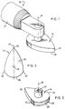
- Figure 1 is a perspective view of a sander;
- Figure 2 is a perspective view of the sanding head of the sander of Figure 1;
- Figure 3 is a schematic plan view from below of the sanding head of Figure 2; and
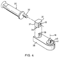
- Figure 4 is a perspective view of a drive mechanism suitable for use in the sander of Figure 1.
- Figure 1 illustrates a
sander 10 comprising ahousing 12 and an oscillatinghead 14. Thehead 14 is driven by a drive mechanism (not shown) and oscillates about anaxis 16 in an angular movement. Thehead 14 has a lower, substantiallyflat sanding surface 18 which is covered with abrasive material and can sand surfaces in a plane substantially perpendicular to theaxis 16. - As can been seen from Figures 2 and 3, the sanding head is of a generally tear-drop shape, terminating at one end in a
vertex 20 and being provided at its other end with a part-cylindrical surface 26, which is centred on theaxis 16. Twofurther vertices cylindrical surface 26. Thesefurther vertices flat sanding surface 18. - Since the part-
cylindrical sanding surface 26 is centred on theaxis 16 of rotation of the sanding head, it too can be used as a sanding surface and, as is illustrated in Figure 2, this surface is also covered with abrasive material. During oscillatory motion of the sanding head, there is no movement of any part of the part-cylindrical sanding surface 26 otherwise than tangential to the surface and this enables thesurface 26 to be employed for sanding in a plane perpendicular to theflat sanding surface 18. Thus, the portable oscillating sander according to the invention possesses the unique capability of sanding in two planes. - Furthermore, the sander can be used to sand simultaneously in two planes and into the corner defined by the two planes, for example where a right-angled corner is required, since the two
sanding surfaces circular edge 25. - As is evident from figure 3, the
sanding head 14 is symmetrical about aplane 27 containing the axis ofrotation 16 and thevertex 20. In addition, the centre of mass of the sanding head lies on the axis ofrotation 16. This symmetry prevents excessive vibration of the sander. It can also be seen that thevertex 20 makes an angle of less than 90 degrees, which enables theflat sanding surface 18 to be used for sanding into a right-angled corner. Again as illustrated in Figure 3, no part of thesanding head 14 projects beyond the extremities of theflat sanding surface 18 when the head is viewed from directly below, i.e. along the axis ofrotation 16. - Figure 4 illustrates a drive mechanism suitable for use in the
sander 10. The mechanism includes adrive shaft 30 which is rotated about its longitudinal axis by a motor (not shown). Aneccentric pin 32, on the end of thedrive shaft 30, is received in rotational engagement in abore 35 of anintermediate member 34. Theintermediate member 34 has a pair of part-cylindrical side surfaces 37, which are engaged within a part-cylindrical recess 38 of ayoke 36 which is free only to rotate about anaxis 16. Theintermediate member 34 oscillates both up and down and from side to side as theshaft 30 rotates. To a small extent, owing to the oscillation of theyoke 36, the intermediate member also oscillates longitudinally along theeccentric pin 32. The movement of theintermediate member 34 is translated into oscillating rotation of theyoke 36 about theaxis 16. - The
yoke 36 is provided with adrive spindle 41 having asquare drive pin 40, centred on theaxis 16 and which is a snap-fit in acorresponding bore 42 of thehead 14, as illustrated in figure 2. Accordingly, thehead 14 can be pulled off thedrive pin 40 and reconnected in different angular orientations as suits the user. - It will of course be appreciated that the present invention has been described above purely by way of example and that modifications of detail may be made without departing from its scope which is defined by the appended claims.
Claims (12)
- A sanding head for a portable oscillating sander, adapted to be attached thereto so as to undergo oscillating relative rotation about a predetermined axis of the head, the sanding head including a substantially flat sanding surface substantially normal to the said axis, characterised by a second sanding surface formed by rotation of a line about an axis substantially coincident with the said predetermined axis.
- A portable oscillating sander including a housing and a sanding head adapted to be attached thereto so as to undergo oscillating relative rotation about a predetermined axis, the sanding head including a substantially flat sanding surface substantially normal to the said axis, characterised by a second sanding surface formed by rotation of a line about an axis substantially coincident with the said predetermined axis.
- A sanding head according to claim 1 or a sander according to claim 2, wherein the said second sanding surface is substantially part-conical.
- A sanding head or a sander according to claim 3 wherein the substantially part-conical surface is substantially part-cylindrical.
- A sanding head or sander according to any preceding claim wherein the substantially flat sanding surface meets the second sanding surface at a substantially part-circular edge.
- A sanding head or sander according to claim 5 wherein the substantially flat sanding surface terminates at a vertex which opposes the substantially part-circular edge.
- A sanding head or sander according to claim 6, wherein the head is substantially symmetric about the plane containing the said predetermined axis and the vertex.
- A sanding head or sander according to claim 6 or claim 7, in which the vertex makes an angle of no more than 90 degrees.
- A sanding head or sander according to any preceding claim wherein the substantially flat surface circumscribes the remainder of the head when viewed along the said predetermined axis.
- A sanding head or sander according to any preceding claim wherein the head is adapted to be attached to the portable oscillating sander in any one of a plurality of angular orientations about the said predetermined axis.
- A sander according to any preceding claim including a drive spindle to which the sanding head is adapted to be attached.
- A sander according to claim 11 wherein the drive spindle includes a regular polygonal drive pin which forms a snap-fit in a corresponding bore in the sanding head, or vice versa.
Applications Claiming Priority (2)
| Application Number | Priority Date | Filing Date | Title |
|---|---|---|---|
| GB9313610 | 1993-07-01 | ||
| GB939313610A GB9313610D0 (en) | 1993-07-01 | 1993-07-01 | Two plane oscillating sander |
Publications (2)
| Publication Number | Publication Date |
|---|---|
| EP0631843A1 EP0631843A1 (en) | 1995-01-04 |
| EP0631843B1 true EP0631843B1 (en) | 1997-12-29 |
Family
ID=10738122
Family Applications (1)
| Application Number | Title | Priority Date | Filing Date |
|---|---|---|---|
| EP19940304807 Expired - Lifetime EP0631843B1 (en) | 1993-07-01 | 1994-06-30 | Two plane oscillating sander |
Country Status (3)
| Country | Link |
|---|---|
| EP (1) | EP0631843B1 (en) |
| DE (1) | DE69407493T2 (en) |
| GB (1) | GB9313610D0 (en) |
Cited By (1)
| Publication number | Priority date | Publication date | Assignee | Title |
|---|---|---|---|---|
| US7438629B2 (en) | 1995-02-09 | 2008-10-21 | Black & Decker Inc. | In-line sander |
Families Citing this family (11)
| Publication number | Priority date | Publication date | Assignee | Title |
|---|---|---|---|---|
| EP0726121A3 (en) * | 1995-02-09 | 1996-10-02 | Porter Cable Corp | In-line sander system |
| US5743791A (en) * | 1995-02-09 | 1998-04-28 | Porter Cable Corporation | Sanding system |
| GB2305876A (en) * | 1995-10-04 | 1997-04-23 | Black & Decker Inc | Detail sanding platen having detachable portion adjacent pointed tip for replacement when worn |
| DE19809937A1 (en) * | 1998-03-07 | 1999-09-09 | Fein C & E | Grinder |
| US6569002B2 (en) | 1999-12-10 | 2003-05-27 | Porter-Cable/Delta | Hand-held oscillating spindle sander |
| JP4866569B2 (en) | 2005-05-27 | 2012-02-01 | 日東工器株式会社 | Polishing tool |
| DE202010017513U1 (en) * | 2010-12-20 | 2012-06-01 | Robert Bosch Gmbh | Grinding plate device for a hand-held grinder |
| US10883579B2 (en) | 2013-12-20 | 2021-01-05 | Robert Bosch Tool Corporation | Oscillating mechanism for a power tool |
| CN112440167A (en) * | 2019-08-30 | 2021-03-05 | 盐城市盐龙水务有限公司 | Wall grinds paper-back edition and puts for building decoration |
| CN113199359A (en) * | 2021-04-21 | 2021-08-03 | 深圳市古安泰自动化技术有限公司 | Visual polisher |
| WO2023140873A1 (en) * | 2022-01-21 | 2023-07-27 | Michael Kettner | Adaptable sanding apparatus and method |
Family Cites Families (4)
| Publication number | Priority date | Publication date | Assignee | Title |
|---|---|---|---|---|
| DE8433109U1 (en) * | 1984-11-13 | 1985-02-21 | Dijs, Johan Daniel, 6101 Fränkisch-Crumbach | ORBITAL GRINDERS |
| EP0333933B1 (en) * | 1988-03-22 | 1993-09-15 | Maeda Kiko Company Limited | Sanding apparatus |
| DE3840974A1 (en) * | 1988-12-06 | 1990-06-07 | Fein C & E | OSCILLATION DRIVE |
| DE4023054A1 (en) * | 1990-07-20 | 1992-01-23 | Stenzel Gmbh | Internal corners grinding machine - has mechanism to convert vertical oscillation of grinding head into horizontal oscillation |
-
1993
- 1993-07-01 GB GB939313610A patent/GB9313610D0/en active Pending
-
1994
- 1994-06-30 EP EP19940304807 patent/EP0631843B1/en not_active Expired - Lifetime
- 1994-06-30 DE DE1994607493 patent/DE69407493T2/en not_active Expired - Lifetime
Cited By (1)
| Publication number | Priority date | Publication date | Assignee | Title |
|---|---|---|---|---|
| US7438629B2 (en) | 1995-02-09 | 2008-10-21 | Black & Decker Inc. | In-line sander |
Also Published As
| Publication number | Publication date |
|---|---|
| DE69407493T2 (en) | 1998-05-20 |
| EP0631843A1 (en) | 1995-01-04 |
| GB9313610D0 (en) | 1993-08-18 |
| DE69407493D1 (en) | 1998-02-05 |
Similar Documents
| Publication | Publication Date | Title |
|---|---|---|
| US5123216A (en) | Portable grinder | |
| EP0631843A1 (en) | Two plane oscillating sander | |
| US4920702A (en) | Portable grinder | |
| US6699111B2 (en) | Hand-guided grinding or sanding device | |
| US5437571A (en) | Detail sander | |
| US5637034A (en) | Detail sander | |
| US4729194A (en) | Balanced orbital sander/grinder | |
| US5533926A (en) | Sandpaper pad and pad support for a detail sander | |
| JPH06320409A (en) | Electric tool | |
| US4744177A (en) | Vibratory abrader | |
| US6846230B2 (en) | Manual machine tool | |
| US3482362A (en) | Double acting sander head | |
| JPH07205013A (en) | Fine grinding machine and its attachment blade | |
| CN110944794B (en) | Grinding tool and its main body and grinding part | |
| GB2337013A (en) | Hand tool having easily separable tool holders | |
| JPH0248154A (en) | Deburring method and device thereof | |
| US4460341A (en) | Dental handpiece | |
| US20030176225A1 (en) | Balanced oscillating tool | |
| JP2003145404A (en) | Electric sander | |
| US7717772B2 (en) | Polishing tool | |
| JPH09150352A (en) | Polishing jig for chisel polishing | |
| US4850149A (en) | Sharpening device | |
| CA1078618A (en) | Drive head | |
| JPH11151652A (en) | Sanda | |
| JP3502194B2 (en) | Sanda |
Legal Events
| Date | Code | Title | Description |
|---|---|---|---|
| PUAI | Public reference made under article 153(3) epc to a published international application that has entered the european phase |
Free format text: ORIGINAL CODE: 0009012 |
|
| AK | Designated contracting states |
Kind code of ref document: A1 Designated state(s): DE FR GB IT |
|
| 17P | Request for examination filed |
Effective date: 19950209 |
|
| GRAG | Despatch of communication of intention to grant |
Free format text: ORIGINAL CODE: EPIDOS AGRA |
|
| 17Q | First examination report despatched |
Effective date: 19970312 |
|
| GRAG | Despatch of communication of intention to grant |
Free format text: ORIGINAL CODE: EPIDOS AGRA |
|
| GRAH | Despatch of communication of intention to grant a patent |
Free format text: ORIGINAL CODE: EPIDOS IGRA |
|
| GRAH | Despatch of communication of intention to grant a patent |
Free format text: ORIGINAL CODE: EPIDOS IGRA |
|
| GRAA | (expected) grant |
Free format text: ORIGINAL CODE: 0009210 |
|
| AK | Designated contracting states |
Kind code of ref document: B1 Designated state(s): DE FR GB IT |
|
| ITF | It: translation for a ep patent filed | ||
| REF | Corresponds to: |
Ref document number: 69407493 Country of ref document: DE Date of ref document: 19980205 |
|
| ET | Fr: translation filed | ||
| PLBQ | Unpublished change to opponent data |
Free format text: ORIGINAL CODE: EPIDOS OPPO |
|
| PLBI | Opposition filed |
Free format text: ORIGINAL CODE: 0009260 |
|
| PLBF | Reply of patent proprietor to notice(s) of opposition |
Free format text: ORIGINAL CODE: EPIDOS OBSO |
|
| 26 | Opposition filed |
Opponent name: C. & E. FEIN GMBH & CO. Effective date: 19980822 |
|
| PLBF | Reply of patent proprietor to notice(s) of opposition |
Free format text: ORIGINAL CODE: EPIDOS OBSO |
|
| PLBF | Reply of patent proprietor to notice(s) of opposition |
Free format text: ORIGINAL CODE: EPIDOS OBSO |
|
| PLBO | Opposition rejected |
Free format text: ORIGINAL CODE: EPIDOS REJO |
|
| PLBN | Opposition rejected |
Free format text: ORIGINAL CODE: 0009273 |
|
| STAA | Information on the status of an ep patent application or granted ep patent |
Free format text: STATUS: OPPOSITION REJECTED |
|
| 27O | Opposition rejected |
Effective date: 20001006 |
|
| REG | Reference to a national code |
Ref country code: GB Ref legal event code: IF02 |
|
| PGFP | Annual fee paid to national office [announced via postgrant information from national office to epo] |
Ref country code: IT Payment date: 20090629 Year of fee payment: 16 |
|
| PGFP | Annual fee paid to national office [announced via postgrant information from national office to epo] |
Ref country code: FR Payment date: 20100630 Year of fee payment: 17 |
|
| PG25 | Lapsed in a contracting state [announced via postgrant information from national office to epo] |
Ref country code: IT Free format text: LAPSE BECAUSE OF NON-PAYMENT OF DUE FEES Effective date: 20100630 |
|
| PGFP | Annual fee paid to national office [announced via postgrant information from national office to epo] |
Ref country code: GB Payment date: 20110628 Year of fee payment: 18 |
|
| PGFP | Annual fee paid to national office [announced via postgrant information from national office to epo] |
Ref country code: DE Payment date: 20110629 Year of fee payment: 18 |
|
| REG | Reference to a national code |
Ref country code: FR Ref legal event code: ST Effective date: 20120229 |
|
| PG25 | Lapsed in a contracting state [announced via postgrant information from national office to epo] |
Ref country code: FR Free format text: LAPSE BECAUSE OF NON-PAYMENT OF DUE FEES Effective date: 20110630 |
|
| GBPC | Gb: european patent ceased through non-payment of renewal fee |
Effective date: 20120630 |
|
| REG | Reference to a national code |
Ref country code: DE Ref legal event code: R119 Ref document number: 69407493 Country of ref document: DE Effective date: 20130101 |
|
| PG25 | Lapsed in a contracting state [announced via postgrant information from national office to epo] |
Ref country code: DE Free format text: LAPSE BECAUSE OF NON-PAYMENT OF DUE FEES Effective date: 20130101 Ref country code: GB Free format text: LAPSE BECAUSE OF NON-PAYMENT OF DUE FEES Effective date: 20120630 |