EP0631438A2 - Television receiver - Google Patents
Television receiver Download PDFInfo
- Publication number
- EP0631438A2 EP0631438A2 EP94304338A EP94304338A EP0631438A2 EP 0631438 A2 EP0631438 A2 EP 0631438A2 EP 94304338 A EP94304338 A EP 94304338A EP 94304338 A EP94304338 A EP 94304338A EP 0631438 A2 EP0631438 A2 EP 0631438A2
- Authority
- EP
- European Patent Office
- Prior art keywords
- vertical
- aspect ratio
- waveform
- signal
- circuit
- Prior art date
- Legal status (The legal status is an assumption and is not a legal conclusion. Google has not performed a legal analysis and makes no representation as to the accuracy of the status listed.)
- Granted
Links
Images


Classifications
-
- H—ELECTRICITY
- H04—ELECTRIC COMMUNICATION TECHNIQUE
- H04N—PICTORIAL COMMUNICATION, e.g. TELEVISION
- H04N7/00—Television systems
- H04N7/01—Conversion of standards, e.g. involving analogue television standards or digital television standards processed at pixel level
-
- H—ELECTRICITY
- H04—ELECTRIC COMMUNICATION TECHNIQUE
- H04N—PICTORIAL COMMUNICATION, e.g. TELEVISION
- H04N7/00—Television systems
- H04N7/01—Conversion of standards, e.g. involving analogue television standards or digital television standards processed at pixel level
- H04N7/0117—Conversion of standards, e.g. involving analogue television standards or digital television standards processed at pixel level involving conversion of the spatial resolution of the incoming video signal
- H04N7/0122—Conversion of standards, e.g. involving analogue television standards or digital television standards processed at pixel level involving conversion of the spatial resolution of the incoming video signal the input and the output signals having different aspect ratios
-
- H—ELECTRICITY
- H04—ELECTRIC COMMUNICATION TECHNIQUE
- H04N—PICTORIAL COMMUNICATION, e.g. TELEVISION
- H04N3/00—Scanning details of television systems; Combination thereof with generation of supply voltages
- H04N3/10—Scanning details of television systems; Combination thereof with generation of supply voltages by means not exclusively optical-mechanical
- H04N3/16—Scanning details of television systems; Combination thereof with generation of supply voltages by means not exclusively optical-mechanical by deflecting electron beam in cathode-ray tube, e.g. scanning corrections
- H04N3/22—Circuits for controlling dimensions, shape or centering of picture on screen
- H04N3/223—Controlling dimensions
-
- H—ELECTRICITY
- H04—ELECTRIC COMMUNICATION TECHNIQUE
- H04N—PICTORIAL COMMUNICATION, e.g. TELEVISION
- H04N3/00—Scanning details of television systems; Combination thereof with generation of supply voltages
- H04N3/10—Scanning details of television systems; Combination thereof with generation of supply voltages by means not exclusively optical-mechanical
- H04N3/16—Scanning details of television systems; Combination thereof with generation of supply voltages by means not exclusively optical-mechanical by deflecting electron beam in cathode-ray tube, e.g. scanning corrections
- H04N3/22—Circuits for controlling dimensions, shape or centering of picture on screen
- H04N3/23—Distortion correction, e.g. for pincushion distortion correction, S-correction
- H04N3/233—Distortion correction, e.g. for pincushion distortion correction, S-correction using active elements
-
- H—ELECTRICITY
- H04—ELECTRIC COMMUNICATION TECHNIQUE
- H04N—PICTORIAL COMMUNICATION, e.g. TELEVISION
- H04N3/00—Scanning details of television systems; Combination thereof with generation of supply voltages
- H04N3/10—Scanning details of television systems; Combination thereof with generation of supply voltages by means not exclusively optical-mechanical
- H04N3/16—Scanning details of television systems; Combination thereof with generation of supply voltages by means not exclusively optical-mechanical by deflecting electron beam in cathode-ray tube, e.g. scanning corrections
- H04N3/27—Circuits special to multi-standard receivers
Definitions
- the present invention relates generally to a television receiver having a display screen with a wide aspect ratio of 16 to 9 and, more particularly, to such a television receiver that can display a video image having a 4 to 3 aspect ratio.
- a television receiver having a display screen with the wide aspect ratio of 16 to 9 has been put into practical use.
- the display of a video signal conformed to a standard aspect ratio of 4 to 3 on a display screen of such a television receiver has been as shown in Figs. 6A to 6C of the accompanying drawings. That is, in the approach resulting in the display of Fig. 6A, portions where no video image is displayed are formed at the right and left ends of the display screen.
- the display of the video signal is expanded such that a horizontal width of the 4 to 3 aspect ratio video image coincides with the horizontal width of the 16 to 9 aspect ratio display screen.
- the portions where no video image is displayed at the right and left ends of the display screen are a disadvantage to the viewer.
- the displaying method of Fig. 6B the upper and lower portions of the video image based on the video signal to be displayed on the display screen are cut off and not seen, so that the viewer is again disadvantaged because he can not see all the video image present in the video signal.
- FIG. 6C there has been proposed another display approach intended as a improvement over the approach of Fig. 6A in which the video image based on the 4 to 3 aspect ratio video signal is expanded in the horizontal direction, so that the video image based on the 4 to 3 aspect ratio video signal coincides with the horizontal and vertical widths of the 16 to 9 aspect ratio display screen. Nevertheless, according to this display method, since the video image on the display screen is compressed in the vertical direction, the visual image looks very unnatural. This system is described in published EP Patent Application 0,551,168, for example.
- Fig. 7A In contrast to the aforesaid various displaying methods, there has been proposed another displaying method resulting in the screen shown in Fig. 7A.
- Fig. 7B representing a conceptual drawing of Fig. 7A, only portions in the vicinity of the right and left ends of the video image on the screen are expanded in the horizontal direction.
- a viewer can see the video image on the screen with little unnatural feeling, because the video image can be displayed naturally at the center portion of the display screen.
- the viewer's visual recognition of the video image becomes weaker at the vicinity of the right and left ends when the viewer looks at the center portion of the display screen.
- a problem to be solved by the present invention is that, according to each of the previously proposed displaying methods as described above, when displaying the video image of the video signal with the standard aspect ratio of 4 to 3 on the display screen with the wide aspect ratio of 16 to 9, there is a fear that the viewer will likely feel the displayed visual image to be unnatural.
- a television receiver wherein, when displaying a video image based on the video signal conformed to the standard aspect ratio of 4 to 3 on a display with the wide aspect ratio of 16 to 9, a horizontal width of the video image of the input video signal screen is made substantially coincident with the horizontal width of the display screen, and the video image based on the input video signal is compressed in the vertical direction at a portion in the vicinity of at least one of the upper and lower edges of the display screen, so that a vertical height of the video image based on the video signal displayed on the display screen is made substantially coincident with the vertical height of the display screen.
- a vertical linearity of the video image on the display screen is changed at the portion in the vicinity of at least one of the upper and lower edges of the display screen so as to be smaller, whereby the video image based on the video signal is compressed in the vertical direction at the portion in the vicinity of at least one of the upper and lower edges of the display screen.
- the video image based on the video signal is compressed in the vertical direction at a portion in the vicinity of at least one of the upper and lower edges of the display screen, so that a vertical height of the video image based on the video signal is made substantially coincident with the vertical height of the display screen, a visual image affecting a viewer with little unnatural feeling can be displayed on the display screen.
- a horizontal width of the video image based on the video signal to be displayed is made substantially coincident with the horizontal width of the display screen. Furthermore, the video image based on the video signal is compressed in the vertical direction in the vicinity of at least one of the upper and lower edges of the display screen, so that a vertical height of the video visual image based on the video signal displayed on the display screen is made substantially coincident with the vertical height of the display screen. In other words, in this case, the video image is compressed only at the portions in the vicinity of the upper and lower edges of the display screen.
- Fig. 1B represents a conceptional drawing of Fig. 1A and the amount of compression is shown by the extent of difference between the rectangles and uniform squares distributed over the face of the screen.
- the video image can be displayed naturally at the center portion of the display screen, so that the viewer can see the visual image on the screen with little unnatural feeling even if the video image moves. This is so because the number of movements of the viewer's view point in the vertical direction is small compared with horizontal view point movements, as described above.
- a drive signal generating circuit 1 for vertical deflection receives a vertical synchronizing signal Vs derived in the known manner from the video signal to be displayed.
- a mode detecting circuit 8 also receives the vertical synchronizing signal Vs, and the mode detecting circuit 8 detects whether the supplied video signal is to be depressed or not.
- the mode detecting circuit 8 outputs a signal fed to a waveform memory 2 via a switch 9.
- the switch 9 can be closed by the viewer when the 4 to 3 aspect ratio signal is to be viewed or the switch 9 can be actuated by the mode detecting circuit 9, as shown by the dashed line in Fig. 2. Alternatively, switch 9 could be eliminated. Then, arbitrary waveform data from a waveform memory 2 is supplied to the drive signal generating circuit 1, and the drive signal generating circuit 1 generates a drive signal Vd for vertical deflection. By arbitrary is meant that the waveform is selected in keeping with practising this invention.
- the drive signal delivered from the drive signal generating circuit 1 is supplied to one end of a vertical deflection yoke 5 through a current limiting resistor 3 and an output amplifier 4.
- the other end of the deflection yoke 5 is grounded through another resistor 6.
- the signal appearing at the connection node between the deflection yoke 5 and the resistor 6 is fed back to the input of the output amplifier 4 through a third resistor 7.
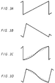
- a drive signal Vd as shown in Fig. 3A, from the drive signal generating circuit 1.
- This is based on the standard waveform data from the waveform memory 2.
- a vertical deflection currently as shown by Fig. 3B is caused to flow through the vertical deflection yoke 5, so that the normal display having the standard vertical linearity characteristic relative to a 16 to 9 aspect ratio is performed.
- Each of the aforesaid displays shown in Figs. 6A and 7A is produced using this standard drive signal Vd.
- a drive signal Vd shown in Fig. 3C is generated from the drive signal generating circuit 1.
- the non-linearity of this signal is based on the so-called arbitrary data from the waveform memory 2.
- a deflection currently as shown by Fig. 3D, is caused to flow through the deflection yoke 5. This results in a display as shown in Fig. 1A in which the visual image based on the video signal is compressed in the vertical direction at the portion in the vicinity of at least one of the upper and lower edges of the 16 to 9 aspect ratio display screen.
- a waveform memory 2 that changes the shape of the waveform of the vertical drive signal in order to correct the vertical linearity of the image on the display screen.
- the vertical linearity of the visual image on the display screen can be changed in the vicinity of at least one of the upper and lower edges of the screen, so as to be smaller in vertical height than it would be otherwise.
- the video image signal is compressed in the vertical direction along at least one of the upper and lower edges of the display screen, so that the vertical height of the video image based on the video signal displayed on the display screen is made substantially coincident with the vertical height of the display screen.
- the video image based on the video signal is compressed in the vertical direction at the portion in the vicinity of at least one of the upper and lower edges of the display screen so that the vertical height of the video image based on the video signal displayed on the display screen is made substantially coincident with the vertical height of the display screen, a visual image affecting a viewer with little unnatural feeling can be displayed on the display screen as a whole.
- the video image of the 4 to 3 aspect ratio video signal is displayed over the entire area of the 16 to 9 aspect ratio display screen and is displayed normally at the center portion thereof, the viewer can see the visual image with little unnatural feeling.
- most ordinary images are symmetrical with respect to a center line running vertically on the screen but few ordinary images are symmetrical with respect to a center line running horizontally on the screen.
- the viewer sees a visual image with less unnatural feeling, even if the video image is distorted in linearity in the vertical direction.
- the degree of distortion of the vertical linearity of the video image is about 10% or slightly more, in order that the vertical height of the 4 to 3 aspect ratio video image based on the video signal displayed on the 16 to 9 aspect ratio display screen is made substantially coincident with the vertical height of the display screen. This degree of distortion is permissible to television receivers at the initial stage of television broadcasting.
- the amount of curvature of the face plate in the vertical direction is larger than that in the horizontal direction.
- the curvature of the face plate in the vertical direction in a cathode ray tube with the aspect ratio of 16 to 9 is larger than that on a cathode ray tube with the standard aspect ratio of 4 to 3.
- This larger curvature of the face plate in the vertical direction is cancelled by the aforesaid modification of the linearity of the video image in the vertical direction, so that it seems visually as if the curvature of the face plate in the vertical direction is made smaller by the modification. This means that any visual unnatural feeling of the video image is further decreased.
- the video image can be displayed satisfactorily even when the video image based on a video software is displayed with the so-called CinemaScope size without performing any trimming. That is, in some of the previously proposed approaches to displaying such video software, subtitles are displayed at the lower portion of the display screen out of the video image as shown in Fig. 4A by the several circles in the lower cross-hatched portion. In this case, such a display as shown in Fig. 4B can be obtained according to the aforesaid circuit arrangement of the present invention.
- the subtitles are represented in Fig. 4B as the larger sized ovals along the bottom of the screen below the image.
- Fig. 5 shows another embodiment of the circuit arrangement for realizing the aforesaid displays according to the present invention, in which a sawtooth signal of the vertical period is supplied to one input of an error amplifier 12 through a resistor 11. An output signal from the error amplifier 12 is supplied to the input of an output amplifier 14 through a resistor 13, and an output signal from the output amplifier 14 is supplied to one end of the vertical deflection yoke 15.
- the other end of the vertical deflection yoke 15 is grounded through a series connected capacitor 16 and resistor 17. Accordingly, a signal having parabolic-shaped waveform with the vertical period, as shown in Fig. 5, is obtained from the other end of the vertical deflection yoke 15. This signal is fed back to the other input of the error amplifier 12 through a resistor 18, a grounded capacitor 19 and a resistor 20. Further, a sawtooth signal having the vertical period, as shown in Fig. 5, is obtained at the connection mode between the capacitor 16 and the resistor 17. This sawtooth signal is fed back to the other input of the error amplifier 12 through a resistor 21.
- a correction waveform signal having the vertical period is supplied to the other input of the error amplifier 12 through a resistor 22, so that the linearity of the video image on the display screen is changed in the vertical direction just like the example shown in Figs. 3C and 3D.
- This correction waveform is shown connected directly to the other aspect of the error amplifier 12, but it is understood that a switch could be provided along with an aspect ratio or mode detecting circuit.
- the present invention may be modified in the following manner. For example, when the upper half of a person is displayed on the screen, the changing ratio of the linearity of the video image corresponding to the upper half of the video image which corresponds to the face of the person may be made smaller but that corresponding to the lower half of the video image may be made larger. Further, in this case, an amount of the changing ratio of the linearity may be selected to be an arbitrary value.
- the present invention may be modified in a manner that the linearity of the video image in the horizontal direction on the display screen is further changed, as in the example shown in Figs. 7A and 7B, in addition to the aforesaid change in the linearity in the vertical direction.
- the amount of change in the linearity can be decreased.
- the aforesaid change in the linearity of the video image may be performed by modifying the video signal through digital signal processing techniques, instead of changing the actual deflection signal waveform as in the above-described embodiments of the present invention.
Landscapes
- Engineering & Computer Science (AREA)
- Multimedia (AREA)
- Signal Processing (AREA)
- Computer Graphics (AREA)
- Details Of Television Scanning (AREA)
- Television Systems (AREA)
Abstract
Description
- The present invention relates generally to a television receiver having a display screen with a wide aspect ratio of 16 to 9 and, more particularly, to such a television receiver that can display a video image having a 4 to 3 aspect ratio.
- A television receiver having a display screen with the wide aspect ratio of 16 to 9 has been put into practical use. Conventionally, the display of a video signal conformed to a standard aspect ratio of 4 to 3 on a display screen of such a television receiver has been as shown in Figs. 6A to 6C of the accompanying drawings. That is, in the approach resulting in the display of Fig. 6A, portions where no video image is displayed are formed at the right and left ends of the display screen. In the approach resulting in the display of Fig. 6B, the display of the video signal is expanded such that a horizontal width of the 4 to 3 aspect ratio video image coincides with the horizontal width of the 16 to 9 aspect ratio display screen.
- According to the displaying method corresponding to Fig. 6A, however, the portions where no video image is displayed at the right and left ends of the display screen are a disadvantage to the viewer. According to the displaying method of Fig. 6B, the upper and lower portions of the video image based on the video signal to be displayed on the display screen are cut off and not seen, so that the viewer is again disadvantaged because he can not see all the video image present in the video signal.
- Further, as shown in Fig. 6C, there has been proposed another display approach intended as a improvement over the approach of Fig. 6A in which the video image based on the 4 to 3 aspect ratio video signal is expanded in the horizontal direction, so that the video image based on the 4 to 3 aspect ratio video signal coincides with the horizontal and vertical widths of the 16 to 9 aspect ratio display screen. Nevertheless, according to this display method, since the video image on the display screen is compressed in the vertical direction, the visual image looks very unnatural. This system is described in published EP Patent Application 0,551,168, for example.
- In contrast to the aforesaid various displaying methods, there has been proposed another displaying method resulting in the screen shown in Fig. 7A. In this method, as shown by Fig. 7B representing a conceptual drawing of Fig. 7A, only portions in the vicinity of the right and left ends of the video image on the screen are expanded in the horizontal direction. According to this method, a viewer can see the video image on the screen with little unnatural feeling, because the video image can be displayed naturally at the center portion of the display screen. In addition, the viewer's visual recognition of the video image becomes weaker at the vicinity of the right and left ends when the viewer looks at the center portion of the display screen.
- When such a display is performed on the screen, however, if the video image based on the video signal moves to the right or to the left, the moving speed of the video image becomes uneven. As a consequence, a viewer feels very unnatural when watching such a moving image. That is, when such a display is performed on the screen, a viewer can see the video image with little unnatural feeling if the view point of the viewer on the screen is fixed, however, the viewer feels very unnatural as the viewer moves his view point to the right or left.
- According to an investigation that has been performed as to the number of movements of the viewer's view point when the viewer views various kinds of programs found in general television broadcasting, it has been proved, as shown by the table of Fig. 8, that the number of movements of view point in the vertical direction is much less by a factor of two to five than the number of movements in the horizontal direction. The present invention has been made in view of this disparity between changes in horizontal and vertical points of view found in general television program material.
- A problem to be solved by the present invention is that, according to each of the previously proposed displaying methods as described above, when displaying the video image of the video signal with the standard aspect ratio of 4 to 3 on the display screen with the wide aspect ratio of 16 to 9, there is a fear that the viewer will likely feel the displayed visual image to be unnatural.
- Therefore, it is an object of the present invention to provide a television receiver having a 16 to 9 aspect ratio screen that can display video images of 4 to 3 aspect ratio that overcomes the above-noted defects inherent in previously proposed systems.
- According to a first aspect of the present invention, there is provided a television receiver wherein, when displaying a video image based on the video signal conformed to the standard aspect ratio of 4 to 3 on a display with the wide aspect ratio of 16 to 9, a horizontal width of the video image of the input video signal screen is made substantially coincident with the horizontal width of the display screen, and the video image based on the input video signal is compressed in the vertical direction at a portion in the vicinity of at least one of the upper and lower edges of the display screen, so that a vertical height of the video image based on the video signal displayed on the display screen is made substantially coincident with the vertical height of the display screen.
- According to another aspect of the television receiver of the present invention, a vertical linearity of the video image on the display screen is changed at the portion in the vicinity of at least one of the upper and lower edges of the display screen so as to be smaller, whereby the video image based on the video signal is compressed in the vertical direction at the portion in the vicinity of at least one of the upper and lower edges of the display screen.
- According to another aspect of the television receiver of the present invention, there is provided a circuit to change a waveform shape of the signal used for correcting vertical linearity of the display screen, so that the vertical linearity of the visual image on the display screen is changed at the portion in the vicinity of at least one of the upper and lower edges of the display screen, so that the image is smaller at those locations.
- According to a yet further aspect of the above-described television receiver according to the present invention, since the video image based on the video signal is compressed in the vertical direction at a portion in the vicinity of at least one of the upper and lower edges of the display screen, so that a vertical height of the video image based on the video signal is made substantially coincident with the vertical height of the display screen, a visual image affecting a viewer with little unnatural feeling can be displayed on the display screen.
- The invention will be further described by way of non-limitative example, with reference to the accompanying drawings, in which:-
- Fig. 1A and Fig. 1B are diagrams used to explain an example of a display of a television receiver according to the present invention;
- Fig. 2 is a circuit arrangement for realizing the display shown in Fig. 1A according to an embodiment of the present invention;
- Figs. 3A to 3D are waveform diagrams used to explain the operation of the circuit of Fig. 2;
- Figs. 4A to 4C are diagrams used to explain a display of the television receiver according to another embodiment of the present invention;
- Fig. 5 is a circuit arrangement for realizing the display shown in Figs. 4A to 4C according to another embodiment of the present invention;
- Figs. 6A to 6C are diagrams used to explain examples of a display according to a previously proposed television receiver;
- Fig. 7A and Fig. 7B are diagram used to explain an example of a display according to a previously proposed television receiver; and
- Fig. 8 is a table used to explain the present invention.
- According to the present invention, as shown in Fig. 1A, a horizontal width of the video image based on the video signal to be displayed is made substantially coincident with the horizontal width of the display screen. Furthermore, the video image based on the video signal is compressed in the vertical direction in the vicinity of at least one of the upper and lower edges of the display screen, so that a vertical height of the video visual image based on the video signal displayed on the display screen is made substantially coincident with the vertical height of the display screen. In other words, in this case, the video image is compressed only at the portions in the vicinity of the upper and lower edges of the display screen. Fig. 1B represents a conceptional drawing of Fig. 1A and the amount of compression is shown by the extent of difference between the rectangles and uniform squares distributed over the face of the screen.
- According to this displaying method, the video image can be displayed naturally at the center portion of the display screen, so that the viewer can see the visual image on the screen with little unnatural feeling even if the video image moves. This is so because the number of movements of the viewer's view point in the vertical direction is small compared with horizontal view point movements, as described above.
- The circuit of Fig. 2 is employed in order to realize the displaying shown in Figs. 1A and 1B. In Fig. 2, a drive
signal generating circuit 1 for vertical deflection receives a vertical synchronizing signal Vs derived in the known manner from the video signal to be displayed. Amode detecting circuit 8 also receives the vertical synchronizing signal Vs, and themode detecting circuit 8 detects whether the supplied video signal is to be depressed or not. When the vertical signal is detected to belong to a signal to be depressed, that is, when the signal being input is of the standard aspect ratio of 4 to 3, themode detecting circuit 8 outputs a signal fed to awaveform memory 2 via aswitch 9. Theswitch 9 can be closed by the viewer when the 4 to 3 aspect ratio signal is to be viewed or theswitch 9 can be actuated by themode detecting circuit 9, as shown by the dashed line in Fig. 2. Alternatively,switch 9 could be eliminated. Then, arbitrary waveform data from awaveform memory 2 is supplied to the drivesignal generating circuit 1, and the drivesignal generating circuit 1 generates a drive signal Vd for vertical deflection. By arbitrary is meant that the waveform is selected in keeping with practising this invention. - The drive signal delivered from the drive
signal generating circuit 1 is supplied to one end of avertical deflection yoke 5 through a current limitingresistor 3 and anoutput amplifier 4. The other end of thedeflection yoke 5 is grounded through anotherresistor 6. The signal appearing at the connection node between thedeflection yoke 5 and theresistor 6 is fed back to the input of theoutput amplifier 4 through a third resistor 7. - According to the thus constituted circuit arrangement, when performing a normal display on the display screen in accordance with the waveform data from the
waveform memory 2, there is generated a drive signal Vd, as shown in Fig. 3A, from the drivesignal generating circuit 1. This is based on the standard waveform data from thewaveform memory 2. A vertical deflection currently as shown by Fig. 3B is caused to flow through thevertical deflection yoke 5, so that the normal display having the standard vertical linearity characteristic relative to a 16 to 9 aspect ratio is performed. Each of the aforesaid displays shown in Figs. 6A and 7A is produced using this standard drive signal Vd. On the other hand, when the mode switching signal from themode detecting circuit 8 is applied through closedswitch 9 to thewaveform memory 2 to change the waveform data delivered to the vertical drive signal generating circuit, a drive signal Vd shown in Fig. 3C, is generated from the drivesignal generating circuit 1. The non-linearity of this signal is based on the so-called arbitrary data from thewaveform memory 2. Then, in response to the drive signal Vd a deflection currently, as shown by Fig. 3D, is caused to flow through thedeflection yoke 5. This results in a display as shown in Fig. 1A in which the visual image based on the video signal is compressed in the vertical direction at the portion in the vicinity of at least one of the upper and lower edges of the 16 to 9 aspect ratio display screen. - According to this circuit arrangement of Fig. 2 there is provided a
waveform memory 2 that changes the shape of the waveform of the vertical drive signal in order to correct the vertical linearity of the image on the display screen. When the waveform is changed by using this waveform data approach, the vertical linearity of the visual image on the display screen can be changed in the vicinity of at least one of the upper and lower edges of the screen, so as to be smaller in vertical height than it would be otherwise. As a consequence, the video image signal is compressed in the vertical direction along at least one of the upper and lower edges of the display screen, so that the vertical height of the video image based on the video signal displayed on the display screen is made substantially coincident with the vertical height of the display screen. - As described above, according to the aforesaid circuit arrangement, since the video image based on the video signal is compressed in the vertical direction at the portion in the vicinity of at least one of the upper and lower edges of the display screen so that the vertical height of the video image based on the video signal displayed on the display screen is made substantially coincident with the vertical height of the display screen, a visual image affecting a viewer with little unnatural feeling can be displayed on the display screen as a whole.
- That is, in the aforesaid circuit arrangement, since the horizontal linearity of the video image displayed on the display screen is always kept normal, a viewer can see the video image on the screen without any unnatural feeling even if the viewer's view point moves in the horizontal direction. In contrast, the viewer can see the video image on the screen with little unnatural feeling even if the viewer's view point is occasionally shifted in the vertical direction, because the number of movements of viewer's view point in the vertical direction is small as described above.
- Furthermore, since the video image of the 4 to 3 aspect ratio video signal is displayed over the entire area of the 16 to 9 aspect ratio display screen and is displayed normally at the center portion thereof, the viewer can see the visual image with little unnatural feeling. In general, most ordinary images are symmetrical with respect to a center line running vertically on the screen but few ordinary images are symmetrical with respect to a center line running horizontally on the screen. Thus, the viewer sees a visual image with less unnatural feeling, even if the video image is distorted in linearity in the vertical direction. Further, the degree of distortion of the vertical linearity of the video image is about 10% or slightly more, in order that the vertical height of the 4 to 3 aspect ratio video image based on the video signal displayed on the 16 to 9 aspect ratio display screen is made substantially coincident with the vertical height of the display screen. This degree of distortion is permissible to television receivers at the initial stage of television broadcasting.
- Furthermore, in the ordinary cathode ray tube the amount of curvature of the face plate in the vertical direction is larger than that in the horizontal direction. Moreover, the curvature of the face plate in the vertical direction in a cathode ray tube with the aspect ratio of 16 to 9 is larger than that on a cathode ray tube with the standard aspect ratio of 4 to 3. This larger curvature of the face plate in the vertical direction is cancelled by the aforesaid modification of the linearity of the video image in the vertical direction, so that it seems visually as if the curvature of the face plate in the vertical direction is made smaller by the modification. This means that any visual unnatural feeling of the video image is further decreased.
- According to the aforesaid circuit arrangement, the video image can be displayed satisfactorily even when the video image based on a video software is displayed with the so-called CinemaScope size without performing any trimming. That is, in some of the previously proposed approaches to displaying such video software, subtitles are displayed at the lower portion of the display screen out of the video image as shown in Fig. 4A by the several circles in the lower cross-hatched portion. In this case, such a display as shown in Fig. 4B can be obtained according to the aforesaid circuit arrangement of the present invention. The subtitles are represented in Fig. 4B as the larger sized ovals along the bottom of the screen below the image.
- Accordingly, in this case, although the subtitles are slightly flattened by the vertical compression, such subtitles can be read without any difficulty and, hence, the viewer can enjoy the video software satisfactorily. In contrast, when such the software is displayed according to the conventional enlarging displaying method, both the upper portion of the video image and the subtitles are cut off and not fully displayed on the screen, as shown in Fig. 4C.
- Fig. 5 shows another embodiment of the circuit arrangement for realizing the aforesaid displays according to the present invention, in which a sawtooth signal of the vertical period is supplied to one input of an
error amplifier 12 through aresistor 11. An output signal from theerror amplifier 12 is supplied to the input of anoutput amplifier 14 through aresistor 13, and an output signal from theoutput amplifier 14 is supplied to one end of thevertical deflection yoke 15. - The other end of the
vertical deflection yoke 15 is grounded through a series connectedcapacitor 16 andresistor 17. Accordingly, a signal having parabolic-shaped waveform with the vertical period, as shown in Fig. 5, is obtained from the other end of thevertical deflection yoke 15. This signal is fed back to the other input of theerror amplifier 12 through aresistor 18, a groundedcapacitor 19 and aresistor 20. Further, a sawtooth signal having the vertical period, as shown in Fig. 5, is obtained at the connection mode between thecapacitor 16 and theresistor 17. This sawtooth signal is fed back to the other input of theerror amplifier 12 through aresistor 21. - According to this circuit arrangement, a correction waveform signal having the vertical period, as shown in Fig. 5, is supplied to the other input of the
error amplifier 12 through aresistor 22, so that the linearity of the video image on the display screen is changed in the vertical direction just like the example shown in Figs. 3C and 3D. This correction waveform is shown connected directly to the other aspect of theerror amplifier 12, but it is understood that a switch could be provided along with an aspect ratio or mode detecting circuit. - Although in the above-described embodiments the linearity of the video image in the vertical direction on the display screen is changed, so that a video image is symmetrical about the center line running horizontally on the screen, the present invention may be modified in the following manner. For example, when the upper half of a person is displayed on the screen, the changing ratio of the linearity of the video image corresponding to the upper half of the video image which corresponds to the face of the person may be made smaller but that corresponding to the lower half of the video image may be made larger. Further, in this case, an amount of the changing ratio of the linearity may be selected to be an arbitrary value.
- Furthermore, the present invention may be modified in a manner that the linearity of the video image in the horizontal direction on the display screen is further changed, as in the example shown in Figs. 7A and 7B, in addition to the aforesaid change in the linearity in the vertical direction. In this case, the amount of change in the linearity can be decreased. The aforesaid change in the linearity of the video image may be performed by modifying the video signal through digital signal processing techniques, instead of changing the actual deflection signal waveform as in the above-described embodiments of the present invention.
- Although the present invention has been described hereinabove with reference to the preferred embodiment, it is to be understood that the invention is not limited to such illustrative embodiment alone, and various modifications may be contrived without departing from the scope thereof as defined by the attached claims.
Claims (12)
- A signal generating circuit for a television display apparatus including a display of a first aspect ratio, the circuit comprising:
an input terminal for receiving one of a video signal of the first aspect ratio and a video signal of a second, different aspect ratio;
a vertical scanning circuit for scanning a vertical scanning height of said video signal to display a video signal received at said input terminal;
characterised by
control means for controlling said vertical scanning circuit to depress said vertical scanning height along at least one of upper and lower edges of a vertical height of said display when said video signal of a second aspect ratio is received at said input terminal. - A circuit according to claim 1, wherein a vertical linearity of a vertical deflection waveform of said vertical scanning circuit is changed at the upper and lower edges of said display so as to be compressed in the vertical direction by said control means.
- A circuit according to claim 2, wherein said vertical linearity is a symmetrical curve over a vertical scanning interval.
- A circuit according to claim 3, wherein said control means comprises a waveform memory for producing data of said symmetrical curve fed to said vertical scanning circuit.
- A circuit according to claim 1, 2, 3 or 4, further comprising a mode detecting circuit for detecting the aspect ratio of the circuit video signal and producing a control signal to be fed to said control means to depress said vertical scanning height according to the detected aspect ratio.
- A circuit according to claim 5, further comprising a switch for selectively connecting said control signal from said mode detecting circuit to said control means.
- A circuit according to claim 1, wherein said vertical scanning circuit comprises an error amplifier receiving at one input a linear sawtooth vertical deflection signal for producing a vertical deflection signal fed to a vertical deflection coil of said vertical scanning circuit, and said control means comprises a capacitor connected to said deflection coil for connecting said deflection coil to ground through a resistor and feedback means for connecting a parabolic waveform signal developed at a connection node between said deflection coil and said capacitor back to a second input of said error amplifier, and wherein said control means further comprises a nonlinear correction waveform signal connected to said second input of said error amplifier.
- A television display apparatus including a signal generating circuit according to any one of the preceding claims.
- A method of displaying a video signal having a 4 to 3 aspect ratio on a video display screen having a 16 to 9 aspect ratio, comprising the steps of:
detecting whether an input video signal for display has the 4 to 3 aspect ratio;
generating a nonlinear correction waveform;
generating a nonlinear vertical deflection waveform from a linear vertical deflection waveform for the 16 to 9 aspect ratio display screen and the generated nonlinear correction waveform;
feeding the generated nonlinear vertical deflection waveform to a vertical deflection coil; and
compressing a video image along the top and bottom edges of the display screen using the nonlinear vertical deflection waveform. - A method according to claim 9, wherein the step of generating a nonlinear correction waveform includes the step of reading out waveform data from a waveform memory in response to said detecting the 4 to 3 aspect ratio of the input video signal.
- A method according to claim 9 or 10, wherein the step of generating a nonlinear correction waveform includes providing a symmetrical sinusoidal waveform over a vertical deflection period.
- A method according to claim 9, wherein said step of generating a nonlinear correction waveform includes the steps of connecting a nonlinear correction waveform signal to a first input of an error amplifier that receives at another input a sawtooth vertical deflection signal and further comprising the step of feeding back to the first input of the error amplifier a parabolic waveform at a connection point between a capacitor and a vertical deflection coil that receives the nonlinear vertical deflection waveform developed by the error amplifier.
Applications Claiming Priority (3)
| Application Number | Priority Date | Filing Date | Title |
|---|---|---|---|
| JP155659/93 | 1993-06-25 | ||
| JP5155659A JPH0715704A (en) | 1993-06-25 | 1993-06-25 | Image receiver |
| JP15565993 | 1993-06-25 |
Publications (3)
| Publication Number | Publication Date |
|---|---|
| EP0631438A2 true EP0631438A2 (en) | 1994-12-28 |
| EP0631438A3 EP0631438A3 (en) | 1995-09-06 |
| EP0631438B1 EP0631438B1 (en) | 1999-08-18 |
Family
ID=15610797
Family Applications (1)
| Application Number | Title | Priority Date | Filing Date |
|---|---|---|---|
| EP94304338A Expired - Lifetime EP0631438B1 (en) | 1993-06-25 | 1994-06-15 | Television receiver |
Country Status (5)
| Country | Link |
|---|---|
| US (1) | US5436669A (en) |
| EP (1) | EP0631438B1 (en) |
| JP (1) | JPH0715704A (en) |
| KR (1) | KR100312146B1 (en) |
| DE (1) | DE69420085T2 (en) |
Cited By (3)
| Publication number | Priority date | Publication date | Assignee | Title |
|---|---|---|---|---|
| DE19717140A1 (en) * | 1997-04-23 | 1998-10-29 | Thomson Brandt Gmbh | Video picture format conversion method |
| WO2005096624A1 (en) * | 2004-03-01 | 2005-10-13 | Thomson Licensing S.A. | Non-linear aspect ratio conversion |
| US6965383B2 (en) * | 2001-12-11 | 2005-11-15 | Lecroy Corporation | Scaling persistence data with interpolation |
Families Citing this family (9)
| Publication number | Priority date | Publication date | Assignee | Title |
|---|---|---|---|---|
| JP2759727B2 (en) * | 1992-04-22 | 1998-05-28 | 日本ビクター株式会社 | Display device |
| JPH07250256A (en) * | 1994-03-08 | 1995-09-26 | Sony Corp | Video equipment and video non-linear processing circuit |
| JPH07298160A (en) * | 1994-04-25 | 1995-11-10 | Hitachi Ltd | Television receiver incorporating video cd reproducing device |
| KR100283574B1 (en) * | 1996-08-27 | 2001-03-02 | 윤종용 | Monitor screen size control circuit and its control method |
| US6191820B1 (en) * | 1998-04-28 | 2001-02-20 | Lg Electronics Inc. | Device and method for converting aspect ratio of video signal |
| CN101365077B (en) * | 2008-09-28 | 2012-06-20 | 华为终端有限公司 | Image scaling method and device |
| US20100123822A1 (en) * | 2008-11-14 | 2010-05-20 | General Instrument Corporation | Method for Converting Between Display Information Scales |
| CN102243858B (en) * | 2011-08-16 | 2012-11-28 | 青岛海信信芯科技有限公司 | Display method and display device |
| JP2015026891A (en) * | 2013-07-24 | 2015-02-05 | ソニー株式会社 | Image processing device and storage medium |
Citations (2)
| Publication number | Priority date | Publication date | Assignee | Title |
|---|---|---|---|---|
| EP0567301A2 (en) * | 1992-04-22 | 1993-10-27 | Victor Company Of Japan, Limited | Display device |
| GB2269955A (en) * | 1992-08-07 | 1994-02-23 | British Broadcasting Corp | Method of showing 16:9 pictures on 4:3 displays |
Family Cites Families (7)
| Publication number | Priority date | Publication date | Assignee | Title |
|---|---|---|---|---|
| US4414571A (en) * | 1980-10-09 | 1983-11-08 | Matsushita Electric Industrial Co., Ltd. | Television receiver |
| GB8304754D0 (en) * | 1983-02-21 | 1983-03-23 | Rca Corp | Variable picture size circuit |
| GB8518803D0 (en) * | 1985-07-25 | 1985-08-29 | Rca Corp | Locating target patterns within images |
| GB8602644D0 (en) * | 1986-02-04 | 1986-03-12 | British Broadcasting Corp | Video systems |
| US4730215A (en) * | 1986-05-30 | 1988-03-08 | Rca Corporation | Compatible wide screen television system with variable image compression/expansion |
| JP3072900B2 (en) * | 1988-08-10 | 2000-08-07 | ソニー株式会社 | Blanking circuit of television receiver |
| NL8901374A (en) * | 1989-05-31 | 1990-12-17 | Philips Nv | A COMBINATION OF A VIDEO TUNER, A VIDEO SIGNAL DISPLAY AND AN IMAGE DISPLAY. |
-
1993
- 1993-06-25 JP JP5155659A patent/JPH0715704A/en active Pending
-
1994
- 1994-06-15 DE DE69420085T patent/DE69420085T2/en not_active Expired - Lifetime
- 1994-06-15 EP EP94304338A patent/EP0631438B1/en not_active Expired - Lifetime
- 1994-06-24 US US08/265,036 patent/US5436669A/en not_active Expired - Lifetime
- 1994-06-24 KR KR1019940014558A patent/KR100312146B1/en not_active IP Right Cessation
Patent Citations (2)
| Publication number | Priority date | Publication date | Assignee | Title |
|---|---|---|---|---|
| EP0567301A2 (en) * | 1992-04-22 | 1993-10-27 | Victor Company Of Japan, Limited | Display device |
| GB2269955A (en) * | 1992-08-07 | 1994-02-23 | British Broadcasting Corp | Method of showing 16:9 pictures on 4:3 displays |
Cited By (3)
| Publication number | Priority date | Publication date | Assignee | Title |
|---|---|---|---|---|
| DE19717140A1 (en) * | 1997-04-23 | 1998-10-29 | Thomson Brandt Gmbh | Video picture format conversion method |
| US6965383B2 (en) * | 2001-12-11 | 2005-11-15 | Lecroy Corporation | Scaling persistence data with interpolation |
| WO2005096624A1 (en) * | 2004-03-01 | 2005-10-13 | Thomson Licensing S.A. | Non-linear aspect ratio conversion |
Also Published As
| Publication number | Publication date |
|---|---|
| EP0631438B1 (en) | 1999-08-18 |
| KR100312146B1 (en) | 2001-12-28 |
| US5436669A (en) | 1995-07-25 |
| JPH0715704A (en) | 1995-01-17 |
| EP0631438A3 (en) | 1995-09-06 |
| KR960003376A (en) | 1996-01-26 |
| DE69420085D1 (en) | 1999-09-23 |
| DE69420085T2 (en) | 2000-02-10 |
Similar Documents
| Publication | Publication Date | Title |
|---|---|---|
| US4951149A (en) | Television system with variable aspect picture ratio | |
| EP0631438B1 (en) | Television receiver | |
| US5249049A (en) | Managing letterbox displays | |
| CA2039143C (en) | Convergence control system for multiple vertical formats | |
| KR0151556B1 (en) | Side by side picture display with reduced cropping | |
| EP0567301A2 (en) | Display device | |
| MY105289A (en) | Vertical zoom and panning for television. | |
| EP0136824B1 (en) | Automatic contrast reduction circuit for a teletext or monitor operation | |
| EP0685139B1 (en) | Adaptive letterbox detection | |
| US8120706B1 (en) | Video system and method for automatic size and position adjustment according to the incoming stream | |
| KR100276575B1 (en) | Managing letterbox display | |
| JP3080985B2 (en) | Raster correction circuit for television equipment | |
| JP3526916B2 (en) | Vertical deflection device having vertical reduction mode | |
| EP0746146B1 (en) | Correction of horizontal and vertical deflection waveforms | |
| US5835813A (en) | Picture display apparatus in which the lower part of the picture is shifted | |
| KR0163716B1 (en) | Tv receiver | |
| JPH07303242A (en) | Television receiver | |
| JPH07307902A (en) | Television receiver | |
| US20040004452A1 (en) | Multi standard television display | |
| JPH08251438A (en) | Video signal processor | |
| KR19990031447A (en) | Wide screen up / down adjustment method | |
| JPS638674B2 (en) | ||
| JPH10257345A (en) | Television receiver | |
| JPH0251985A (en) | Television signal system converter | |
| JPH0865595A (en) | Image processor, image processing method and television receiver |
Legal Events
| Date | Code | Title | Description |
|---|---|---|---|
| PUAI | Public reference made under article 153(3) epc to a published international application that has entered the european phase |
Free format text: ORIGINAL CODE: 0009012 |
|
| AK | Designated contracting states |
Kind code of ref document: A2 Designated state(s): DE FR GB |
|
| PUAL | Search report despatched |
Free format text: ORIGINAL CODE: 0009013 |
|
| AK | Designated contracting states |
Kind code of ref document: A3 Designated state(s): DE FR GB |
|
| 17P | Request for examination filed |
Effective date: 19951011 |
|
| 17Q | First examination report despatched |
Effective date: 19980306 |
|
| GRAG | Despatch of communication of intention to grant |
Free format text: ORIGINAL CODE: EPIDOS AGRA |
|
| GRAG | Despatch of communication of intention to grant |
Free format text: ORIGINAL CODE: EPIDOS AGRA |
|
| GRAH | Despatch of communication of intention to grant a patent |
Free format text: ORIGINAL CODE: EPIDOS IGRA |
|
| GRAH | Despatch of communication of intention to grant a patent |
Free format text: ORIGINAL CODE: EPIDOS IGRA |
|
| GRAA | (expected) grant |
Free format text: ORIGINAL CODE: 0009210 |
|
| AK | Designated contracting states |
Kind code of ref document: B1 Designated state(s): DE FR GB |
|
| REF | Corresponds to: |
Ref document number: 69420085 Country of ref document: DE Date of ref document: 19990923 |
|
| ET | Fr: translation filed | ||
| PLBE | No opposition filed within time limit |
Free format text: ORIGINAL CODE: 0009261 |
|
| STAA | Information on the status of an ep patent application or granted ep patent |
Free format text: STATUS: NO OPPOSITION FILED WITHIN TIME LIMIT |
|
| 26N | No opposition filed | ||
| REG | Reference to a national code |
Ref country code: GB Ref legal event code: IF02 |
|
| PGFP | Annual fee paid to national office [announced via postgrant information from national office to epo] |
Ref country code: DE Payment date: 20130620 Year of fee payment: 20 Ref country code: GB Payment date: 20130619 Year of fee payment: 20 |
|
| PGFP | Annual fee paid to national office [announced via postgrant information from national office to epo] |
Ref country code: FR Payment date: 20130703 Year of fee payment: 20 |
|
| REG | Reference to a national code |
Ref country code: DE Ref legal event code: R071 Ref document number: 69420085 Country of ref document: DE |
|
| REG | Reference to a national code |
Ref country code: GB Ref legal event code: PE20 Expiry date: 20140614 |
|
| PG25 | Lapsed in a contracting state [announced via postgrant information from national office to epo] |
Ref country code: GB Free format text: LAPSE BECAUSE OF EXPIRATION OF PROTECTION Effective date: 20140614 |
|
| PG25 | Lapsed in a contracting state [announced via postgrant information from national office to epo] |
Ref country code: DE Free format text: LAPSE BECAUSE OF EXPIRATION OF PROTECTION Effective date: 20140617 |