EP0631432B1 - Video camera with electronical picture stabilizer - Google Patents
Video camera with electronical picture stabilizer Download PDFInfo
- Publication number
- EP0631432B1 EP0631432B1 EP19940110045 EP94110045A EP0631432B1 EP 0631432 B1 EP0631432 B1 EP 0631432B1 EP 19940110045 EP19940110045 EP 19940110045 EP 94110045 A EP94110045 A EP 94110045A EP 0631432 B1 EP0631432 B1 EP 0631432B1
- Authority
- EP
- European Patent Office
- Prior art keywords
- motion vector
- value
- correlative
- average
- detection areas
- Prior art date
- Legal status (The legal status is an assumption and is not a legal conclusion. Google has not performed a legal analysis and makes no representation as to the accuracy of the status listed.)
- Expired - Lifetime
Links
Images


Classifications
-
- H—ELECTRICITY
- H04—ELECTRIC COMMUNICATION TECHNIQUE
- H04N—PICTORIAL COMMUNICATION, e.g. TELEVISION
- H04N5/00—Details of television systems
- H04N5/14—Picture signal circuitry for video frequency region
- H04N5/144—Movement detection
- H04N5/145—Movement estimation
-
- H—ELECTRICITY
- H04—ELECTRIC COMMUNICATION TECHNIQUE
- H04N—PICTORIAL COMMUNICATION, e.g. TELEVISION
- H04N23/00—Cameras or camera modules comprising electronic image sensors; Control thereof
-
- H—ELECTRICITY
- H04—ELECTRIC COMMUNICATION TECHNIQUE
- H04N—PICTORIAL COMMUNICATION, e.g. TELEVISION
- H04N23/00—Cameras or camera modules comprising electronic image sensors; Control thereof
- H04N23/60—Control of cameras or camera modules
- H04N23/68—Control of cameras or camera modules for stable pick-up of the scene, e.g. compensating for camera body vibrations
- H04N23/681—Motion detection
- H04N23/6811—Motion detection based on the image signal
-
- H—ELECTRICITY
- H04—ELECTRIC COMMUNICATION TECHNIQUE
- H04N—PICTORIAL COMMUNICATION, e.g. TELEVISION
- H04N23/00—Cameras or camera modules comprising electronic image sensors; Control thereof
- H04N23/60—Control of cameras or camera modules
- H04N23/68—Control of cameras or camera modules for stable pick-up of the scene, e.g. compensating for camera body vibrations
- H04N23/682—Vibration or motion blur correction
- H04N23/683—Vibration or motion blur correction performed by a processor, e.g. controlling the readout of an image memory
Definitions
- the present invention relates to a video camera. More specifically, the present invention relates to a compact video camera with electronic picture stabilizer, which is utilized as a camcorder, for example.
- One example of a method for detecting an unintentional motion component of an image sensing device is disclosed in, for example, the 2 ⁇ th image engineering conference in 1989 by Matsushita Electric Industrial Corporation.
- this prior art method by utilizing a motion vector obtained by a representative point matching method disclosed in, for example, JP-A- 61(1986)-2 ⁇ 1581, the motion component of the image sensing device is detected according to image information.
- an electronic picture stabilization is performed on the basis of a whole motion vector obtained from the image information.
- the whole motion vector is evaluated by averaging the portion motion vectors of the four detection areas, or the whole motion vector is evaluated by averaging portion motion vectors of two portion motion vectors having intermediate values of the four portion motion vectors, whereby the electronic picture stabilization is performed on the basis of the whole motion vector thus evaluated.
- an electronic picture stabilizer for electronically stabilizing the picture taken by the camera against unintentional motion by using a whole motion vector
- EP-A-0 392 671 discloses an image motion vector detector including means for detecting motion vectors in motion vector detection regions defined in the whole or part of a picture frame, means for judging the reliability of the motion vector in each region and means for outputting a representative value of a set of reliable motion vectors as amotion vector of the frame in case the number of motion vectors judged to be reliable is more than or equal to predetermined number. Vectors in detection regions containing moving image portions are judged to be not reliable.
- a principal object of the present invention is to provide a video camera having a novel electronic picture stabilizer.
- Another object of the present invention is to provide a video camera with electronic picture stabilizer capable of accurately performing the electronic picture stabilization.
- valid detection area determinating means includes first means for evaluating correlative values of pixels at a present field or frame on the basis of an image signal of a last field or frame and an image signal of the present field or frame; means for evaluating an average correlative value that is a mean value of the correlative values; means for evaluating a minimum correlative value that is a minimum value out of the correlative values; means for evaluating a value obtained by dividing the average correlative value by the minimum correlative value; means for evaluating a gradient associated with the minimum correlative value; and means for determined whether or not a motion vector is correctly detected in accordance with whether or not the following conditions are satisfied:
- the threshold values to be compared with the gradient are changed in accordance with the average correlative value.
- the threshold value to be compared with the gradient is set to be large as indicated by the condition (C)
- the threshold value to be compared with the gradient is set to be small as indicated by the condition (D). Therefore, the gradient can be compared with the threshold value in corresponding to a change of the contrast in the screen (the third threshold value or the fourth threshold value), and therefore, determination whether or not an object having repeated pattern exists in the image field becomes to be performed more correctly.
- each of respective detection areas defined within the screen image field is a valid detection area by the valid detection area determinating means through determination whether or not all of the above described conditions are satisfied in respect to the detection area.
- first, a first absolute value and a second absolute value are evaluated for each detection area by first calculation means and second calculation means, respectively.
- first calculation means and second calculation means By adding the first absolute value and the second absolute value to each other for each detection area by addition means so as to obtain a first dispersion, and the arbitrary number of the first dispersions are selected by selection means in order of small.
- a whole motion vector is detected on the basis of portion motion vectors of the detection areas representing the selected first dispersions.
- a portion motion vector of an arbitrary invalid detection area is replaced with the whole motion vector of a field or frame before the present field or frame by first replacement means. Thereafter, the portion motion vector of the invalid detection area that is replaced with the whole motion vector and the portion motion vectors of the valid detection areas are utilized for detecting the whole motion vector at the present field or frame according to the above described processing.
- the number of valid detection areas is zero, as the whole motion vector of the present field or frame, a resulted vector by multiplying the whole motion vector evaluated one field or frame before by a predetermined coefficient less than 1 (decimal number less than 1) is utilized.
- a detecting method for detecting the whole motion vector is changed according to the number of valid detection areas, even if a portion motion vector that is not caused by the unintentional motion of the camera is detected in performing the electronic image stabilization, the influence thereof becomes very small, and therefore, it becomes possible to accurately detect an unintentional motion amount. Therefore, the unintentional motion of the camera can be corrected with precision.
- the whole motion vector may be evaluated on the basis of a second dispersion as described in the following. More specifically, first, the second dispersion is evaluated by second dispersion calculation means by utilizing an average vector of the portion motion vectors, that is evaluated by averaging means, and the portion motion vectors of the respective detection areas. A fact that the second dispersion is large indicates that variation of the portion motion vectors is large. This tendency occurs in a case where there is an object which moves in only a portion of the screen. On the other hand, a fact that the second dispersion is small means that the variation of the portion motion vectors is small. This tendency occurs in a case where no moving object exists on the screen, or a case where there is an object which moves all over the screen.
- the whole motion vector by utilizing the portion motion vector of the case where the second dispersion is large the whole motion vector having low reliability is obtained.
- the whole motion vector is evaluated by utilizing the portion motion vector of the case whether the second dispersion is small, the whole motion vector having high reliability is obtained. Therefore, in the case where the second dispersion is large, a value of the whole motion vector is made small by multiplying the average vector of the portion motion vectors by a small coefficient. Furthermore, in the case where the second dispersion is small, a value of the whole motion vector is made large by multiplying the average vector of the portion motion vectors by a large coefficient. That is, the whole motion vector of the case of the large second dispersion is not used as possible, and in contrast, the whole motion vector of the case of the small second dispersion is used as possible.
- a degree of a magnitude of the second dispersion is determined by comparing means, and the whole motion vector is detected in accordance with a comparison result.
- the whole motion vector is detected in accordance with the magnitude of the second dispersion, and therefore, it is possible to more correctly detect the whole motion vector. Accordingly, the unintentional motion amount can be detected with precision.
- a video camera 1 ⁇ of a preferred embodiment shown in Figure 1 includes a solid-state image sensing device 12 such as a CCD (Charge-Coupled Device) which converts an optical signal being inputted from an object (not shown) through a lens 14 into an electric signal.
- the electric signal from the solid-state image sensing device 12 is inputted to a camera circuit 16.
- the camera circuit 16 includes a sample-hold circuit by which the electric signal from the solid-state image sensing device 12 is sampled and held. The level of the electric signal thus sampled and held is adjusted by an AGC (Automatic Gain Control), and synchronization signals are added to the electric signal by a synchronization signal adding circuit (not shown).
- AGC Automatic Gain Control
- the camera circuit 16 converts the electric signal from the solid-state image sensing device 12 into an analog video signal.
- the analog video signal is further converted into a digital video signal by an A/D converter 18.
- the digital video signal is applied to a motion detecting circuit 2 ⁇ .
- the motion detecting circuit 2 ⁇ for example, an LSI "L7A ⁇ 948" manufactured by Sanyo Electric Co., Ltd. may be utilized.
- the digital video signal is written into a field memory 24 field by field.
- the motion detecting circuit 2 ⁇ evaluates, for each of four detection areas A, B, C and D shown in Figure 3, the position of one point having the highest correlation degree (a minimum correlative value) and positions of four points around the one point, and correlative values by utilizing a well-known representative point matching method.
- the position data and the correlative value data are applied to a microcomputer 26.
- the motion detecting circuit 2 ⁇ shown in Figure 1 includes an input end 28 which receives the digital video signal from the A/D converter 18.
- the digital video signal inputted to the input end 28 is applied to the representative point memory 32 and a subtracting circuit 34, respectively, through a filter 3 ⁇ .
- the filter 3 ⁇ is a kind of digital low-pass filter which is utilized for improvement of an S/N ratio so as to secure a significant detection accuracy with a lesser number of representative points.
- the representative point memory 32 stores position data and luminance data of a plurality of representative points within each of the respective detection areas A-D shown in Figure 3.
- each of the detection areas is divided into thirty (3 ⁇ ) regions, and therefore, thirty (3 ⁇ ) representative points are determined, and accordingly, the representative point memory 32 stores the position data and the luminance data of the thirty (3 ⁇ ) representative points.
- Each of the divided regions 42 ( Figure 4) is constituted by 32 pixels in a horizontal direction (X direction) x 16 pixels in a vertical direction (Y direction).
- the subtracting circuit 34 executes subtracting operations of the luminance data of the representative point of the last field read-out the representative point memory 32 and luminance data of all the pixels of the present field applied from the input end 28 via the filter 3 ⁇ , and obtains absolute values of subtraction results. That is, the subtracting circuit 34 evaluates a luminance difference between the luminance data of the present field and the luminance data of the last field, and applies the luminance differences to an accumulating and adding circuit 36.
- the accumulating and adding circuit 36 executes an accumulation and addition of the luminance differences of thirty (3 ⁇ ) in this embodiment obtained by the subtracting circuit 34 of the same position or pixel in the same region 42 so as to output correlative values data.
- the correlative values data is applied to an arithmetic operation circuit 38 which evaluates a minimum correlative value and calculates an average correlative value for each of the detection areas A-D, and evaluates position data of the pixel having the minimum correlative value.
- Data of the minimum correlative value, average correlative value and positions thus obtained by the arithmetic operation circuit 38 is applied to the above described microcomputer 26 from an output end 4 ⁇ .
- arithmetic operations for the correlative values can be performed by the above described LSI "L7A ⁇ 948".
- a motion vector of a whole of a screen i.e. the image field 44 ( Figure 3) (simply called as "whole motion vector") is calculated on the basis of the position data and the correlative value data.
- a deviation of a pixel indicative of the minimum correlative value from the representative point is evaluated on the basis of the position data of that pixel, and the deviation is made as a portion motion vector.
- an internal interpolation is preformed by utilizing the correlative values of the four pixels around the pixel having the minimum correlative value so as to calculate the position data of the pixel having the minimum correlative value.
- the microcomputer 26 further evaluates a propriety of the portion motion vector detected for each detection area, that is, determines whether each of the detection areas is a valid detection area or an invalid detection area on the basis of the status of the image.
- a propriety of the portion motion vector detected for each detection area that is, determines whether each of the detection areas is a valid detection area or an invalid detection area on the basis of the status of the image.
- the change of the correlative value with respect to the coordinate positions becomes similar to Figure 11 (described later).
- conditions (A) - (C) are defined as follows.
- ⁇ , ⁇ , ⁇ , ⁇ , and ⁇ are constant threshold values, and ⁇ ⁇ ⁇ .
- the microcomputer 26 determines whether or not the contrast of the screen is low in accordance with the above described condition (A). The microcomputer 26 further determines whether or not the moving object exists within the detection area on the basis of the above described condition (B). Furthermore, the microcomputer 26 determines whether or not the object having repeated pattern exists in the detection area on the basis of the above described condition (C) at a time that the average correlative value is equal to or larger than the threshold value ⁇ , or the above described condition (D) at a time that the average correlative value is smaller than the threshold value ⁇ .
- the correlative value becomes small.
- the reliability of the detection result is small, and therefore, only when the condition (A) is satisfied, that is, the average correlative value > ⁇ , the detection area is determined as the valid detection area.
- the threshold value ⁇ can be determined through field tests or examinations. Thus, on the basis of the average correlative value, it is determined whether or not the screen has low contrast.
- the correlative value at a portion occupied by the moving object and the correlative value no moving object exists are different from each other.
- Various kinds of correlative values are obtained by the portion occupied by the moving object, and the correlative value from that portion becomes a large value generally (the correlation degree becomes low). Therefore, when the moving object exists within the detection area, there is a possibility that the minimum correlative value becomes large, and the portion motion vector of that detection area may be erroneously detected.
- the microcomputer 26 determines the presence or absence of the moving object by evaluating the value of the average correlative value / the minimum correlative value.
- one point having the minimum correlative value and the correlative values of four points around the one point are utilized so as to detect the object having repeated pattern (stripes, for example).
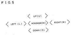
- the correlative values of the four points at left, right, up, and down are L, R, U, and D as shown in Figure 5.
- the differences between the respective correlative values, i.e. L - M, R - M, U - M and D - M are calculated, and a minimum value of the differences is defined as the gradient.
- the gradient is compared with the threshold value ⁇ that is determined through field tests.
- the detection area is determined as the invalid detection area.
- the gradient is compared with the threshold value ⁇ that is determined through field tests. If the gradient is larger than the threshold value ⁇ , the detection area is determined as the valid detection area, and if the gradient is equal to or smaller than the threshold value ⁇ , it is determined that the detection area is the invalid detection area.
- each of the detection areas is the valid detection area.
- the motion amount between the fields i.e. the whole motion vector is determined. Therefore, the whole motion vector is representative of the motion amount between the fields and a direction thereof.
- the whole motion vector thus evaluated is applied to the memory control circuit 22.
- a start address for reading-out the field memory 24 is determined on the basis of the whole motion vector, and therefore, the digital video signal stored in the field memory 24 becomes to be read-out at the start address. That is, the memory control circuit 22 moves an extracting area 46 ( Figure 6) formed by the digital video signal from the field memory 24 in accordance with the whole motion vector calculated by the microcomputer 26.
- an electronic zooming circuit 48 ( Figure 1) is utilized.
- the electronic zooming circuit 48 defines the image extracting area 46 wherein an image is enlarged according to a zooming magnification with respect to the image field 44.
- a position of the image extracting area 46 can be freely moved within a range of the image field 44 by changing the start address for reading-out the digital video signal from the field memory 24. Then, in order to obtain a video signal for a whole area of the image field 24 on the basis of the digital video signal extracted from the image extracting area 46, an image is enlarged by utilizing an internal interpolation on the basis of the digital video signal read-out the field memory 24.
- an image from the video camera 1 ⁇ is blurred, and resulting in a case where an object person exists in a left-lower portion within the image field 44 (shown at an upper portion in Figure 7) or a case where an object person exists at a right-upper portion within the image field (shown at a lower portion in Figure 47). Therefore, by moving the image extracting area 46 at every field according to the whole motion vector that is calculated by the microcomputer 26, as shown at a right portion in Figure 7, the object person can be just positioned in the image extracting area 46.
- the digital video signal thus outputted from the electronic zooming circuit 48 is converted into an analog signal by a D/A converter 52 so as to be outputted from an output terminal 54.
- processings set forth in the following may be executed by the microcomputer 26.
- the microcomputer 26 evaluates a mean value of four portion motion vectors (average vector) and a mean value of portion motion vectors of the valid detection areas, respectively.
- a dispersion is calculated by the microcomputer 26.
- a degree of variation of the portion motion vector of each of the detection areas is evaluated according to the dispersion.
- the dispersion is represented by the following equations.
- X direction dispersion ⁇ (
- Y direction dispersion ⁇ (
- a dispersion coefficient Hk is determined, and by multiplying the dispersion coefficient Hk by the mean value of the portion motion vectors of the valid detection areas, the whole motion vector is calculated.
- the dispersion coefficient Hk is determined in the X direction and the Y direction, respectively, and the X direction dispersion coefficient is multiplied to the X direction component of the means value of the portion motion vectors of the valid detection areas, and the Y direction dispersion coefficient is multiplied to the Y direction component of the mean value of the portion motion vectors.
- a minimum one of the four portion motion vectors is defined as the whole motion vector.
- the whole motion vector is calculated by multiplying the dispersion coefficient Hk to the mean value of the portion motion vectors of the valid detection areas; however, there is no valid detection area, the whole motion vector is defined as "the whole motion vector of the present field x a coefficient less than 1".
- the coefficient less than 1 in the embodiment shown, " ⁇ .97" is utilized.
- the whole motion vector is evaluated by utilizing the portion motion vectors of a case where the dispersion is large, the whole motion vector having low reliability is obtained.
- the whole motion vector is evaluated by utilizing the portion motion vectors of a case where the dispersion is small, the whole motion vector having high reliability is obtained.
- the whole motion vector is made smaller by multiplying a small dispersion coefficient Hk to the mean value of the portion motion vectors.
- the dispersion is small, by multiplying a large dispersion coefficient Hk to the mean value of the portion motion vectors, the whole motion vector is made larger. That is, the whole motion vector of the case where the dispersion is large is not used as possible, and in contrast, the whole motion vector of the case where the dispersion is small is used as possible, so that the whole motion vector having high reliability can be obtained.
- the unintentional motion is corrected, that is, the electronic picture stabilization is performed.
- n of the detection area is initially set as "1". If the average correlative value of the detection area n is larger than the threshold value ⁇ in a step S3, the process proceeds to a step S5 wherein it is determined whether or not the value obtained by dividing the average correlative value by the minimum correlative value is larger than the threshold value ⁇ . If the value is larger than the threshold value ⁇ in the step S5, in a step S7, it is determined whether or not the average correlative value is equal to or larger than the threshold value ⁇ .
- a step S9 it is determined whether or not the gradient of the detection area n is larger than the threshold value ⁇ . If “YES” is determined in the step S9, in a step S13, the detection area n is determined as a valid detection area. On the other hand, if the average correlative value is smaller than the threshold value ⁇ in the step S7, in a step S11, it is determined whether or not the gradient of the detection area n is larger than the threshold value ⁇ . If "YES" is determined in the step S11, in a step S13, the detection area n is determined as a valid detection area.
- the process proceeds to a step S15 in which, the detection area n is determined as an invalid detection area.
- step S17 After the step S13 or the step S15, in a step S17, "n" indicative of the detection area is incremented by 1. Then, in a step S19, it is determined whether or not "n” is equal to or smaller than "4", and if "YES", the process returns to the step S3. That is, the above described processings are repeated until “n” exceeds "4" in the step S19. If “n” exceeds "4" in the step S19, the process proceeds to a step S21 shown in Figure 9.
- step S21 the number of the valid detection areas is counted.
- step S23 it is determined whether or not the number of the valid detection areas is "4", and if "NO", in a step S25, it is determined whether or not the number of the valid detection areas is "3". If “YES” is determined in the step S23 or the step S25, that is, if the number of the valid detection areas is more than "3", in a step S27, mean values are calculated of the X (horizontal, for example) direction portion motion vectors and the Y (vertical, for example) direction portion motion vectors are calculated for each of the valid detection areas.
- a step S29 by utilizing the mean values calculated in the step S27, an absolute value of the X direction and an absolute value of the Y direction are evaluated for each of the valid detection areas, and then, the X direction absolute value and the Y direction absolute value are added to each other for each detection area to obtain the dispersion.
- the X direction absolute value is an absolute value of a difference between the X direction portion motion vectors of the respective detection areas and the mean value of the X direction portion motion vectors of the valid detection areas.
- the Y direction absolute value is an absolute value of a difference between the Y direction portion motion vectors of the respective detection areas and the mean value of the Y direction portion motion vectors of the valid detection areas.
- a step S31 two dispersions having smaller values are selected from the four dispersions calculated in the step S29, and a mean value of the portion motion vectors of the detect ion areas corresponding to the selected dispersions is calculated. Then, in a step S33, the mean value is used as the whole motion vector.
- a step S35 it is determined whether or not the number of the valid detection areas is "2". If the number of the valid detection areas is "2", in a step S37, the portion motion vector of an arbitrary one of the invalid detection areas is replaced with the whole motion vector evaluated before one field, and then, the process proceeds to the step S27. Then, through the execution of the steps S27 - S33, the whole motion vector is determined. In this embodiment shown, the portion motion vector of one of the two invalid detection area is replaced by the whole motion vector of the last field, but the portion motion vector of the remaining invalid detection area is not replaced with the whole motion vector. Therefore, the whole motion vector is determined on the basis of the portion motion vectors of the two valid detection areas and the portion motion vector of the invalid detection area being replaced with the whole motion vector.
- step S39 it is determined whether or not the number of the valid detection areas is "1". If “YES” is determined in the step S39, in a step S41, the portion motion vectors of arbitrary two invalid detection areas are replaced with the whole motion vector evaluated one field before and the whole motion vector evaluated two fields before, respectively, and the process proceeds to the step S27. Then, through the execution of the steps S27 - S33, the whole motion vector can be evaluated.
- the portion motion vectors of the two invalid detection areas out of the three invalid detection areas are replaced with the whole motion vector evaluated one field before and the whole motion vector evaluated two field before, respectively, and for the remaining one invalid detection area, the portion motion vector is not replaced with the whole motion vector. Therefore, in this embodiment shown, the whole motion vector is determined on the basis of the portion motion vector of one valid detection area and the portion motion vectors of the two invalid detection area being replaced with the whole motion vectors .
- step S43 by multiplying the coefficient " ⁇ .97" to the whole motion vector evaluated one field before, the whole motion vector of the present field in the step S33 is obtained.
- the unintentional motion is corrected by utilizing the whole motion vector according to the number of the valid detection areas; however, a correction method itself is well known, and therefore, a detailed description thereof is omitted here.
- the determination whether or not there is an object having repeated pattern within the detection areas can be made correctly, and the detection area may not be determined as the invalid detection area even if the contrast of the screen is slightly lowered. Therefore, the validation or the invalidation of the detection areas can be correctly determined, and accordingly, the detection accuracy of the whole motion vector becomes to be increased.
- the detection accuracy is largely affected by the status of the input image. Therefore, the propriety of the detected motion vector is evaluated by the microcomputer in accordance with the status of the image.
- Figure 11 is a graph showing a change of a correlative value with respect to coordinate positions in a case where the representative matching method is utilized.
- the correlative value has a sharp minimum point indicative of the minimum correlative value, and the motion vector is determined on the basis of the position of the minimum correlative value.
- the minimum correlative value can not be sharply detected, and therefore, the detection accuracy of the motion vector becomes to be deteriorated.
- a motion vector is determined by utilizing the motion vectors obtained from the valid detection areas only. As a method for determinating the motion vector, an averaging of the motion vectors of the valid detection areas is utilized, for example.
- the threshold value ⁇ of the condition (C) is to be made smaller.
- the threshold value ⁇ is made smaller irrespective of the contrast of the screen, it may be erroneously determined whether or not there is an object having a repeating pattern in the screen, and therefore, the detection accuracy of the motion vector is dropped.
- the gradient is compared with the large threshold value or the small threshold value according to another condition, such a problem can be solved.
- the correlative value is calculated through accumulation and addition of the luminance differences; however, the correlative value may be evaluated by utilizing a difference of the electric signals from the solid-state image sensing device 12 between the adjacent fields (frames) instead of the luminance differences.
- step S31 only one dispersion may be selected, that is, the arbitrary number of dispersions may be selected.
- the coefficient utilized in the step S43 is not limited to " ⁇ .97", and therefore, an arbitrary coefficient having a value larger than zero but smaller than 1 may be utilized.
- the four detection areas are defined within the image field in the above described embodiments; however, the number of the detection areas is arbitrary, and the larger number of the detection areas, the better the detection accuracy.
- the luminance difference is evaluated between the adjacent fields; however, the same may be evaluated between the adjacent frames. Furthermore, the replacement of the whole motion vector and etc. may be performed not a unit of field but a unit of frame.
Description
- The present invention relates to a video camera. More specifically, the present invention relates to a compact video camera with electronic picture stabilizer, which is utilized as a camcorder, for example.
- One example of a method for detecting an unintentional motion component of an image sensing device is disclosed in, for example, the 2⊘th image engineering conference in 1989 by Matsushita Electric Industrial Corporation. In this prior art method, by utilizing a motion vector obtained by a representative point matching method disclosed in, for example, JP-A- 61(1986)-2⊘1581, the motion component of the image sensing device is detected according to image information. In this prior art, an electronic picture stabilization is performed on the basis of a whole motion vector obtained from the image information.
- More specifically, in this prior art, four detection areas are arranged in an image field, and four portion motion vectors are obtained from the image field. Then, the whole motion vector is evaluated by averaging the portion motion vectors of the four detection areas, or the whole motion vector is evaluated by averaging portion motion vectors of two portion motion vectors having intermediate values of the four portion motion vectors, whereby the electronic picture stabilization is performed on the basis of the whole motion vector thus evaluated.
- However, in such a method, in a case where an object passed through a detection area, for example, when there is a detection area in which a portion motion vector which is not caused by the unintentional motion of the camera is detected, the whole motion vector is affected by this detection area, and therefore, the motion of the camera can not be accurately detected, and thus, the electronic picture stabilization can not be performed with precision.
- SMPTE Journal vol. 101, no. 2, February 1992, White Plains, NY USA pages 66 to 75 , K. UOMORI et al., 'Electronic Image Stabilization System for Video Cameras and VCRs' ET AL discloses an electronic image stabilization system which can be incorporated into a compact video camera.
- In particular an electronic picture stabilizer for electronically stabilizing the picture taken by the camera against unintentional motion by using a whole motion vector;
- portion motion vector detecting means for detecting a portion motion vector of each of a plurality of detection areas of an image field;
- valid detection area determining means for determining whether or not each of the detections areas is a valid detection area through determination whether or not each of the portion motion vectors is effective for detecting an unintentional motion of a camera;
- said valid detection area determining means including
- first means for evaluating correlative values of pixels through comparison of an image signal of the last field and an image signal of the present field;
- means for evaluating an average correlative value that is a mean of the correlative values;
- means for evaluating a minimum correlative value that is a minimum of the correlative values ;
- means for evaluating value obtained by dividing the average correlative value by the minimum correlative value; and
- means for evaluating a gradient associated with the minimum correlative value, and
- means for determining whether or not the portion motion vector is correctly detected in
accordance with the following conditions:
- (A) average correlative value > first threshold value; and
- (B) value obtained by dividing average correlative value by minimum correlative value > second threshold; and
- whole motion vector detecting means for detecting a whole motion vector in accordance with the number of the valid detection areas;
- said whole motion vector detecting means includes dispersion calculating means for obtaining a dispersion on the basis of the respective portion motion vector indicating an absolute deviation of the respective portion motion vector from an average motion vector of all valid detection areas are disclosed.
-
- EP-A-0 392 671 discloses an image motion vector detector including means for detecting motion vectors in motion vector detection regions defined in the whole or part of a picture frame, means for judging the reliability of the motion vector in each region and means for outputting a representative value of a set of reliable motion vectors as amotion vector of the frame in case the number of motion vectors judged to be reliable is more than or equal to predetermined number. Vectors in detection regions containing moving image portions are judged to be not reliable.
- Therefore, a principal object of the present invention is to provide a video camera having a novel electronic picture stabilizer.
- Another object of the present invention is to provide a video camera with electronic picture stabilizer capable of accurately performing the electronic picture stabilization.
- In a video camera according to the present invention as defined in
claim 1, valid detection area determinating means includes first means for evaluating correlative values of pixels at a present field or frame on the basis of an image signal of a last field or frame and an image signal of the present field or frame; means for evaluating an average correlative value that is a mean value of the correlative values; means for evaluating a minimum correlative value that is a minimum value out of the correlative values; means for evaluating a value obtained by dividing the average correlative value by the minimum correlative value; means for evaluating a gradient associated with the minimum correlative value; and means for determined whether or not a motion vector is correctly detected in accordance with whether or not the following conditions are satisfied: - (A) the average correlative value > a first threshold value;
- (B) the value obtained by dividing the average correlative value by the minimum correlative value > a second threshold value;
- (C) the gradient > a third threshold value (when the average correlative value ≧ a fifth threshold value); and
- (D) the gradient > a fourth threshold value (when the average correlative value < the fifth threshold value), the third threshold value being equal to or larger than the fourth threshold value (the third threshold value ≧ the fourth threshold value).
-
- As indicated in the above described conditions (C) and (D), the threshold values to be compared with the gradient are changed in accordance with the average correlative value. When a contrast in a screen is large, that is, when the average correlative value is large, the threshold value to be compared with the gradient is set to be large as indicated by the condition (C), and when the contrast in the screen is small, that is, when the average correlative value is small, the threshold value to be compared with the gradient is set to be small as indicated by the condition (D). Therefore, the gradient can be compared with the threshold value in corresponding to a change of the contrast in the screen (the third threshold value or the fourth threshold value), and therefore, determination whether or not an object having repeated pattern exists in the image field becomes to be performed more correctly.
- Then, it is determined whether or not each of respective detection areas defined within the screen image field is a valid detection area by the valid detection area determinating means through determination whether or not all of the above described conditions are satisfied in respect to the detection area.
- In a case where the number of the valid detection areas is larger than a predetermined threshold value, first, a first absolute value and a second absolute value are evaluated for each detection area by first calculation means and second calculation means, respectively. By adding the first absolute value and the second absolute value to each other for each detection area by addition means so as to obtain a first dispersion, and the arbitrary number of the first dispersions are selected by selection means in order of small. A whole motion vector is detected on the basis of portion motion vectors of the detection areas representing the selected first dispersions.
- When the number of the valid detection areas is less than the predetermined value, first, a portion motion vector of an arbitrary invalid detection area is replaced with the whole motion vector of a field or frame before the present field or frame by first replacement means. Thereafter, the portion motion vector of the invalid detection area that is replaced with the whole motion vector and the portion motion vectors of the valid detection areas are utilized for detecting the whole motion vector at the present field or frame according to the above described processing.
- Furthermore, the number of valid detection areas is zero, as the whole motion vector of the present field or frame, a resulted vector by multiplying the whole motion vector evaluated one field or frame before by a predetermined coefficient less than 1 (decimal number less than 1) is utilized.
- In accordance with the present invention, since a detecting method for detecting the whole motion vector is changed according to the number of valid detection areas, even if a portion motion vector that is not caused by the unintentional motion of the camera is detected in performing the electronic image stabilization, the influence thereof becomes very small, and therefore, it becomes possible to accurately detect an unintentional motion amount. Therefore, the unintentional motion of the camera can be corrected with precision.
- It is correctly determined whether or not the object having repeated pattern (stripe or the like) exists in the image, and a detection area is hardly determined as an invalid detection area even when the contrast in the screen is slightly fallen, and therefore, a detection accuracy of the motion vector is increased.
- Furthermore, the whole motion vector may be evaluated on the basis of a second dispersion as described in the following. More specifically, first, the second dispersion is evaluated by second dispersion calculation means by utilizing an average vector of the portion motion vectors, that is evaluated by averaging means, and the portion motion vectors of the respective detection areas. A fact that the second dispersion is large indicates that variation of the portion motion vectors is large. This tendency occurs in a case where there is an object which moves in only a portion of the screen. On the other hand, a fact that the second dispersion is small means that the variation of the portion motion vectors is small. This tendency occurs in a case where no moving object exists on the screen, or a case where there is an object which moves all over the screen.
- Therefore, if the whole motion vector by utilizing the portion motion vector of the case where the second dispersion is large, the whole motion vector having low reliability is obtained. In contrast, if the whole motion vector is evaluated by utilizing the portion motion vector of the case whether the second dispersion is small, the whole motion vector having high reliability is obtained. Therefore, in the case where the second dispersion is large, a value of the whole motion vector is made small by multiplying the average vector of the portion motion vectors by a small coefficient. Furthermore, in the case where the second dispersion is small, a value of the whole motion vector is made large by multiplying the average vector of the portion motion vectors by a large coefficient. That is, the whole motion vector of the case of the large second dispersion is not used as possible, and in contrast, the whole motion vector of the case of the small second dispersion is used as possible.
- In addition, a degree of a magnitude of the second dispersion is determined by comparing means, and the whole motion vector is detected in accordance with a comparison result.
- In accordance with the present invention, by grasping a status of the screen through evaluation of the second dispersion, the whole motion vector is detected in accordance with the magnitude of the second dispersion, and therefore, it is possible to more correctly detect the whole motion vector. Accordingly, the unintentional motion amount can be detected with precision.
- The above described objects and other objects, features, aspects and advantages of the present invention will become more apparent from the following detailed description of the present invention when taken in conjunction with the accompanying drawings.
- Figure 1 is a block diagram showing one embodiment according to the present invention;
- Figure 2 is a block diagram showing a motion detecting circuit of Figure 1 embodiment;
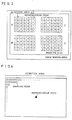
- Figure 3 is an illustrative view showing a principle of an electronic zooming and detection areas within an image field;
- Figure 4 is an illustrative view showing a principle of the electronic zooming and representative points and sampling points in the detection areas;
- Figure 5 is an illustrative view showing a method for detecting an object having repeated pattern by utilizing a pixel having a minimum correlative value and four pixels around the same;
- Figure 6 is an illustrative view showing a principle of an electronic picture stabilization;
- Figure 7 is an illustrative view showing the detection areas within the image field, to which a representative point matching method is applied;
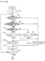
- Figure 8 is a flowchart showing an operation of the embodiment;
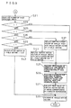
- Figure 9 is a flowchart showing an operation succeeding to Figure 8; and
- Figure 10 is a graph showing a change of correlative values in respect to coordinate positions for each image status in a case where the representative point matching method is utilized.
-
- A
video camera 1⊘ of a preferred embodiment shown in Figure 1 includes a solid-stateimage sensing device 12 such as a CCD (Charge-Coupled Device) which converts an optical signal being inputted from an object (not shown) through alens 14 into an electric signal. The electric signal from the solid-stateimage sensing device 12 is inputted to acamera circuit 16. As well known, thecamera circuit 16 includes a sample-hold circuit by which the electric signal from the solid-stateimage sensing device 12 is sampled and held. The level of the electric signal thus sampled and held is adjusted by an AGC (Automatic Gain Control), and synchronization signals are added to the electric signal by a synchronization signal adding circuit (not shown). Thus, thecamera circuit 16 converts the electric signal from the solid-stateimage sensing device 12 into an analog video signal. The analog video signal is further converted into a digital video signal by an A/D converter 18. The digital video signal is applied to amotion detecting circuit 2⊘. As themotion detecting circuit 2⊘, for example, an LSI "L7A⊘948" manufactured by Sanyo Electric Co., Ltd. may be utilized. Under control of amemory control circuit 22 which is included in the same LSI constituting themotion detecting circuit 2⊘, the digital video signal is written into afield memory 24 field by field. - The
motion detecting circuit 2⊘ evaluates, for each of four detection areas A, B, C and D shown in Figure 3, the position of one point having the highest correlation degree (a minimum correlative value) and positions of four points around the one point, and correlative values by utilizing a well-known representative point matching method. The position data and the correlative value data are applied to amicrocomputer 26. - More specifically, with referring Figure 2, the
motion detecting circuit 2⊘ shown in Figure 1 includes aninput end 28 which receives the digital video signal from the A/D converter 18. The digital video signal inputted to theinput end 28 is applied to therepresentative point memory 32 and a subtractingcircuit 34, respectively, through afilter 3⊘. Thefilter 3⊘ is a kind of digital low-pass filter which is utilized for improvement of an S/N ratio so as to secure a significant detection accuracy with a lesser number of representative points. Therepresentative point memory 32 stores position data and luminance data of a plurality of representative points within each of the respective detection areas A-D shown in Figure 3. In this embodiment shown, each of the detection areas is divided into thirty (3⊘) regions, and therefore, thirty (3⊘) representative points are determined, and accordingly, therepresentative point memory 32 stores the position data and the luminance data of the thirty (3⊘) representative points. Each of the divided regions 42 (Figure 4) is constituted by 32 pixels in a horizontal direction (X direction) x 16 pixels in a vertical direction (Y direction). - The subtracting
circuit 34 executes subtracting operations of the luminance data of the representative point of the last field read-out therepresentative point memory 32 and luminance data of all the pixels of the present field applied from theinput end 28 via thefilter 3⊘, and obtains absolute values of subtraction results. That is, the subtractingcircuit 34 evaluates a luminance difference between the luminance data of the present field and the luminance data of the last field, and applies the luminance differences to an accumulating and addingcircuit 36. The accumulating and addingcircuit 36 executes an accumulation and addition of the luminance differences of thirty (3⊘) in this embodiment obtained by the subtractingcircuit 34 of the same position or pixel in thesame region 42 so as to output correlative values data. The correlative values data is applied to anarithmetic operation circuit 38 which evaluates a minimum correlative value and calculates an average correlative value for each of the detection areas A-D, and evaluates position data of the pixel having the minimum correlative value. Data of the minimum correlative value, average correlative value and positions thus obtained by thearithmetic operation circuit 38 is applied to the above describedmicrocomputer 26 from anoutput end 4⊘. In addition, such arithmetic operations for the correlative values can be performed by the above described LSI "L7A⊘948". - Then, in the
microcomputer 26, a motion vector of a whole of a screen, i.e. the image field 44 (Figure 3) (simply called as "whole motion vector") is calculated on the basis of the position data and the correlative value data. - First, a deviation of a pixel indicative of the minimum correlative value from the representative point is evaluated on the basis of the position data of that pixel, and the deviation is made as a portion motion vector. In addition, in order to make the detection accuracy of the portion motion vector good, an internal interpolation is preformed by utilizing the correlative values of the four pixels around the pixel having the minimum correlative value so as to calculate the position data of the pixel having the minimum correlative value.
- In addition, the
microcomputer 26 further evaluates a propriety of the portion motion vector detected for each detection area, that is, determines whether each of the detection areas is a valid detection area or an invalid detection area on the basis of the status of the image. In this embodiment shown, since the representative point matching method is utilized, the change of the correlative value with respect to the coordinate positions becomes similar to Figure 11 (described later). - Now, in order to determine whether or not the contrast of the screen is low, whether or not there is a moving object in the detection area, and whether or not there is an object having repeated pattern (stripes, for example) in the detection area, conditions (A) - (C) are defined as follows.
- (A) average correlative value > α ;
- (B) value obtained by dividing average correlative value by minimum correlative value > β ;
- (C) gradient > γ (when average correlative value ≧ ε ); and
- (D) gradient > δ (when average correlative value < ε )
-
- In addition, α , β , γ , δ , and ε are constant threshold values, and γ ≧ δ . For example, the threshold values are set as α = 36, β = 7, γ = 8, δ = 4, and ε = 128.
- The
microcomputer 26 determines whether or not the contrast of the screen is low in accordance with the above described condition (A). Themicrocomputer 26 further determines whether or not the moving object exists within the detection area on the basis of the above described condition (B). Furthermore, themicrocomputer 26 determines whether or not the object having repeated pattern exists in the detection area on the basis of the above described condition (C) at a time that the average correlative value is equal to or larger than the threshold value ε , or the above described condition (D) at a time that the average correlative value is smaller than the threshold value ε . These processings are executed for each of the detection areas A - D so that it is determined whether or not the portion motion vector of each of the detection areas A - D is erroneously detected due to the moving object or the like other than the unintentional motion and thus reliable, that is, whether or not each of the detection areas A - D is the valid detection area. If a detection area satisfies all the above described conditions (A) - (D), the detection areas is the valid detection area, and if any one of the above described conditions is not satisfied, the detection area is determined as an invalid detection area. - In concrete, whether or not the detection area is a valid detection area is determined as follows:
- At first, when the contrast of the screen is low, the luminance difference is small, and therefore, the correlative value becomes small. When the whole screen is white, for example, the correlative value is small. In such a case, the reliability of the detection result is small, and therefore, only when the condition (A) is satisfied, that is, the average correlative value > α , the detection area is determined as the valid detection area. In addition, the threshold value α can be determined through field tests or examinations. Thus, on the basis of the average correlative value, it is determined whether or not the screen has low contrast.
- Furthermore, when the moving object exists in the detection area, the correlative value at a portion occupied by the moving object and the correlative value no moving object exists are different from each other. Various kinds of correlative values are obtained by the portion occupied by the moving object, and the correlative value from that portion becomes a large value generally (the correlation degree becomes low). Therefore, when the moving object exists within the detection area, there is a possibility that the minimum correlative value becomes large, and the portion motion vector of that detection area may be erroneously detected. If the portion motion vector is erroneously detected, the whole motion vector is also erroneously detected; however, when the average correlative value is large, the portion motion vector is reliable even if the minimum correlative value is large at some extent. On the other hand, when the average correlative value is small, the portion motion vector is reliable only when the minimum correlative value is smaller. Therefore, in concrete, the detection area is determined as the valid detection area when (the average correlative value / the minimum correlative value) > 7, and if this condition is not satisfied, the portion motion vector of the detection area is not utilized so as to avoid the influence due to the above described erroneous detection. Thus, the
microcomputer 26 determines the presence or absence of the moving object by evaluating the value of the average correlative value / the minimum correlative value. - Furthermore, in the
microcomputer 26, one point having the minimum correlative value and the correlative values of four points around the one point are utilized so as to detect the object having repeated pattern (stripes, for example). - More specifically, on the assumption that the minimum correlative value is M, and the correlative values of the four points at left, right, up, and down are L, R, U, and D as shown in Figure 5. The differences between the respective correlative values, i.e. L - M, R - M, U - M and D - M are calculated, and a minimum value of the differences is defined as the gradient. When the average correlative value is equal to or larger than the threshold value ε , the gradient is compared with the threshold value γ that is determined through field tests. Then, if the gradient is larger than the threshold value γ , it is determined that the detection area is the valid detection area, and if the gradient is equal to or smaller than the threshold value γ , the detection area is determined as the invalid detection area. On the other hand, when the average correlative value is smaller than the threshold value ε , the gradient is compared with the threshold value δ that is determined through field tests. If the gradient is larger than the threshold value δ , the detection area is determined as the valid detection area, and if the gradient is equal to or smaller than the threshold value δ , it is determined that the detection area is the invalid detection area.
- Thus, in accordance with the conditions (A) - (D), it is determined whether or not each of the detection areas is the valid detection area.
- Then, in accordance with the number of valid detection areas, the motion amount between the fields, i.e. the whole motion vector is determined. Therefore, the whole motion vector is representative of the motion amount between the fields and a direction thereof.
- The whole motion vector thus evaluated is applied to the
memory control circuit 22. In thememory control circuit 22, a start address for reading-out thefield memory 24 is determined on the basis of the whole motion vector, and therefore, the digital video signal stored in thefield memory 24 becomes to be read-out at the start address. That is, thememory control circuit 22 moves an extracting area 46 (Figure 6) formed by the digital video signal from thefield memory 24 in accordance with the whole motion vector calculated by themicrocomputer 26. - In addition, since the extracting
area 46 can not be moved by the digital video signal read-out from thefield memory 24 as it is, an electronic zooming circuit 48 (Figure 1) is utilized. - With referring Figure 6, the electronic zooming circuit 48 (Figure 1) defines the
image extracting area 46 wherein an image is enlarged according to a zooming magnification with respect to theimage field 44. A position of theimage extracting area 46 can be freely moved within a range of theimage field 44 by changing the start address for reading-out the digital video signal from thefield memory 24. Then, in order to obtain a video signal for a whole area of theimage field 24 on the basis of the digital video signal extracted from theimage extracting area 46, an image is enlarged by utilizing an internal interpolation on the basis of the digital video signal read-out thefield memory 24. - Thus, by zooming-up an image of an arbitrary
image extracting area 46 within theimage field 44 in an electronic manner by the electronic zooming circuit 48 (Figure 1), acorrectable range 5⊘ that is equal to a difference between theimage field 44 and theimage extracting area 46 can be formed. - If an unintentional motion occurs in the
video camera 1⊘ as shown in Figure 7 according to a vibration of a hand of a person who operates thevideo camera 1⊘, an image from thevideo camera 1⊘ is blurred, and resulting in a case where an object person exists in a left-lower portion within the image field 44 (shown at an upper portion in Figure 7) or a case where an object person exists at a right-upper portion within the image field (shown at a lower portion in Figure 47). Therefore, by moving theimage extracting area 46 at every field according to the whole motion vector that is calculated by themicrocomputer 26, as shown at a right portion in Figure 7, the object person can be just positioned in theimage extracting area 46. - The digital video signal thus outputted from the
electronic zooming circuit 48 is converted into an analog signal by a D/A converter 52 so as to be outputted from anoutput terminal 54. - In addition, the processings set forth in the following may be executed by the
microcomputer 26. - At first, the
microcomputer 26 evaluates a mean value of four portion motion vectors (average vector) and a mean value of portion motion vectors of the valid detection areas, respectively. - Then, a dispersion is calculated by the
microcomputer 26. A degree of variation of the portion motion vector of each of the detection areas is evaluated according to the dispersion. The dispersion is represented by the following equations. - In accordance with the dispersion as described later, a dispersion coefficient Hk is determined, and by multiplying the dispersion coefficient Hk by the mean value of the portion motion vectors of the valid detection areas, the whole motion vector is calculated. In addition, it is needless to say that the dispersion coefficient Hk is determined in the X direction and the Y direction, respectively, and the X direction dispersion coefficient is multiplied to the X direction component of the means value of the portion motion vectors of the valid detection areas, and the Y direction dispersion coefficient is multiplied to the Y direction component of the mean value of the portion motion vectors.
- (1) ⊘ ≦ dispersion < 8: Hk = 1
- (2) 8 ≦ dispersion < 16: Hk = ⊘.75
- (3) 16 ≦ dispersion < 24: Hk = ⊘.5
- (2) 24 ≦ dispersion < 32: Hk = ⊘.25
-
- In addition, in a case where the dispersion exceeds "32", a minimum one of the four portion motion vectors is defined as the whole motion vector.
- Thus, if there is a valid detection area, the whole motion vector is calculated by multiplying the dispersion coefficient Hk to the mean value of the portion motion vectors of the valid detection areas; however, there is no valid detection area, the whole motion vector is defined as "the whole motion vector of the present field x a coefficient less than 1". In addition, as the coefficient less than 1, in the embodiment shown, "⊘.97" is utilized.
- In addition, a reason why the dispersion coefficient is set stepwise in accordance with the magnitude of the dispersion is as follows:
- A fact that the dispersion is large indicates that the variation of the each of respective portion motion vectors is large. This tendency occurs in a case where a moving object exists at only a portion of the screen. On the other hand, a fact that the dispersion is small indicates that the variation of each of the respective portion motion vectors is small. This tendency occurs in a case where no moving object exists in the screen, or a case where a moving object which moves all over the screen exists.
-
- Therefore, if the whole motion vector is evaluated by utilizing the portion motion vectors of a case where the dispersion is large, the whole motion vector having low reliability is obtained. On the other hand, if the whole motion vector is evaluated by utilizing the portion motion vectors of a case where the dispersion is small, the whole motion vector having high reliability is obtained. Accordingly, when the dispersion is large, the whole motion vector is made smaller by multiplying a small dispersion coefficient Hk to the mean value of the portion motion vectors. Furthermore, when the dispersion is small, by multiplying a large dispersion coefficient Hk to the mean value of the portion motion vectors, the whole motion vector is made larger. That is, the whole motion vector of the case where the dispersion is large is not used as possible, and in contrast, the whole motion vector of the case where the dispersion is small is used as possible, so that the whole motion vector having high reliability can be obtained.
- By utilizing the whole motion vector thus obtained, in accordance with the above described manner, the unintentional motion is corrected, that is, the electronic picture stabilization is performed.
- With referring Figures 8 and 9, a major operation in the
microcomputer 26 of thevideo camera 1⊘ will be described. In addition, in a flowchart of Figure 8, "n" ("1" to "4") is corresponding to the detection area A to the detection area D. - In a step S1 shown in Figure 8, "n" of the detection area is initially set as "1". If the average correlative value of the detection area n is larger than the threshold value α in a step S3, the process proceeds to a step S5 wherein it is determined whether or not the value obtained by dividing the average correlative value by the minimum correlative value is larger than the threshold value β . If the value is larger than the threshold value β in the step S5, in a step S7, it is determined whether or not the average correlative value is equal to or larger than the threshold value ε . If the average correlative value is equal to or larger than the threshold value ε , in a step S9, it is determined whether or not the gradient of the detection area n is larger than the threshold value γ . If "YES" is determined in the step S9, in a step S13, the detection area n is determined as a valid detection area. On the other hand, if the average correlative value is smaller than the threshold value ε in the step S7, in a step S11, it is determined whether or not the gradient of the detection area n is larger than the threshold value δ . If "YES" is determined in the step S11, in a step S13, the detection area n is determined as a valid detection area.
- At a time that the averaged correlative value of the detection area n is equal to or smaller than the threshold value α in the step S3, a time that the value obtained by dividing the average correlative value of the detection area n by the minimum correlative value is equal to or smaller than the threshold value β in the step S5, a time that the gradient of the detection area n is equal to or smaller than the threshold value γ in the step S9, or a time that the gradient of the detection area n is equal to or smaller than the threshold value δ in the step S11, the process proceeds to a step S15 in which, the detection area n is determined as an invalid detection area.
- After the step S13 or the step S15, in a step S17, "n" indicative of the detection area is incremented by 1. Then, in a step S19, it is determined whether or not "n" is equal to or smaller than "4", and if "YES", the process returns to the step S3. That is, the above described processings are repeated until "n" exceeds "4" in the step S19. If "n" exceeds "4" in the step S19, the process proceeds to a step S21 shown in Figure 9.
- In the step S21, the number of the valid detection areas is counted. In a step S23, it is determined whether or not the number of the valid detection areas is "4", and if "NO", in a step S25, it is determined whether or not the number of the valid detection areas is "3". If "YES" is determined in the step S23 or the step S25, that is, if the number of the valid detection areas is more than "3", in a step S27, mean values are calculated of the X (horizontal, for example) direction portion motion vectors and the Y (vertical, for example) direction portion motion vectors are calculated for each of the valid detection areas. Then, in a step S29, by utilizing the mean values calculated in the step S27, an absolute value of the X direction and an absolute value of the Y direction are evaluated for each of the valid detection areas, and then, the X direction absolute value and the Y direction absolute value are added to each other for each detection area to obtain the dispersion. The X direction absolute value is an absolute value of a difference between the X direction portion motion vectors of the respective detection areas and the mean value of the X direction portion motion vectors of the valid detection areas. Furthermore, the Y direction absolute value is an absolute value of a difference between the Y direction portion motion vectors of the respective detection areas and the mean value of the Y direction portion motion vectors of the valid detection areas. Then, in a step S31, two dispersions having smaller values are selected from the four dispersions calculated in the step S29, and a mean value of the portion motion vectors of the detect ion areas corresponding to the selected dispersions is calculated. Then, in a step S33, the mean value is used as the whole motion vector.
- On the other hand, if "NO" is determined in the step S25, in a step S35, it is determined whether or not the number of the valid detection areas is "2". If the number of the valid detection areas is "2", in a step S37, the portion motion vector of an arbitrary one of the invalid detection areas is replaced with the whole motion vector evaluated before one field, and then, the process proceeds to the step S27. Then, through the execution of the steps S27 - S33, the whole motion vector is determined. In this embodiment shown, the portion motion vector of one of the two invalid detection area is replaced by the whole motion vector of the last field, but the portion motion vector of the remaining invalid detection area is not replaced with the whole motion vector. Therefore, the whole motion vector is determined on the basis of the portion motion vectors of the two valid detection areas and the portion motion vector of the invalid detection area being replaced with the whole motion vector.
- If it is determined that the number of the valid detection areas is not "2" in the step S35, in a step S39, it is determined whether or not the number of the valid detection areas is "1". If "YES" is determined in the step S39, in a step S41, the portion motion vectors of arbitrary two invalid detection areas are replaced with the whole motion vector evaluated one field before and the whole motion vector evaluated two fields before, respectively, and the process proceeds to the step S27. Then, through the execution of the steps S27 - S33, the whole motion vector can be evaluated. In this embodiment shown, the portion motion vectors of the two invalid detection areas out of the three invalid detection areas are replaced with the whole motion vector evaluated one field before and the whole motion vector evaluated two field before, respectively, and for the remaining one invalid detection area, the portion motion vector is not replaced with the whole motion vector. Therefore, in this embodiment shown, the whole motion vector is determined on the basis of the portion motion vector of one valid detection area and the portion motion vectors of the two invalid detection area being replaced with the whole motion vectors .
- If the number of the valid detection areas is not "1", that is, it is determined that all the detection areas are invalid detection areas in the step S39, in a step S43, by multiplying the coefficient "⊘.97" to the whole motion vector evaluated one field before, the whole motion vector of the present field in the step S33 is obtained.
- Thus, the unintentional motion is corrected by utilizing the whole motion vector according to the number of the valid detection areas; however, a correction method itself is well known, and therefore, a detailed description thereof is omitted here.
- In accordance with this embodiment, the determination whether or not there is an object having repeated pattern within the detection areas can be made correctly, and the detection area may not be determined as the invalid detection area even if the contrast of the screen is slightly lowered. Therefore, the validation or the invalidation of the detection areas can be correctly determined, and accordingly, the detection accuracy of the whole motion vector becomes to be increased.
- That is, according to the above described embodiment, the disadvantages of the prior art set forth in the following can be eliminated.
- In the prior art method wherein the unintentional motion component is detected from the image information, the detection accuracy is largely affected by the status of the input image. Therefore, the propriety of the detected motion vector is evaluated by the microcomputer in accordance with the status of the image.
- Figure 11 is a graph showing a change of a correlative value with respect to coordinate positions in a case where the representative matching method is utilized. Normally, as shown by a solid line a in Figure 11, the correlative value has a sharp minimum point indicative of the minimum correlative value, and the motion vector is determined on the basis of the position of the minimum correlative value. In contrast, if the contrast of the screen is low, or if a moving object exists in the screen, as shown by a one-dotted line b or a dotted line c in Figure 11, the minimum correlative value can not be sharply detected, and therefore, the detection accuracy of the motion vector becomes to be deteriorated. Furthermore, in a case where there is an object having repeated pattern (striped image) in the screen, it becomes very difficult to detect the motion vector. In order to determine the above described image status, in the prior art method, the following conditions are set with respect to the correlative value:
- (A) average correlative value > α ;
- (B) value obtained by dividing average correlative value by minimum correlative value > β ; and
- (C) gradient > γ wherein, α , β and γ are constant threshold values, and for example, the same are set as α = 36, β = 7 and γ = 8.
-
- In the prior art method, for each of the detection areas, it is determined whether or not the above described conditions (A) - (C) are satisfied. Then, if any one of the conditions is satisfied, the detection area is determined as an invalid detection area, and if all the conditions are satisfied, the detection area is determined as a valid detection area. Then, a motion vector is determined by utilizing the motion vectors obtained from the valid detection areas only. As a method for determinating the motion vector, an averaging of the motion vectors of the valid detection areas is utilized, for example.
- However, in the above described conditions of the prior art method, if the contrast of the screen becomes to be slightly lowered, even when the condition (A) is satisfied, the condition (C) is not satisfied, and therefore, the threshold value γ of the condition (C) is to be made smaller. However, the threshold value γ is made smaller irrespective of the contrast of the screen, it may be erroneously determined whether or not there is an object having a repeating pattern in the screen, and therefore, the detection accuracy of the motion vector is dropped. In contrast, in the above described, embodiment, the gradient is compared with the large threshold value or the small threshold value according to another condition, such a problem can be solved.
- In addition, in the above described embodiment, the correlative value is calculated through accumulation and addition of the luminance differences; however, the correlative value may be evaluated by utilizing a difference of the electric signals from the solid-state
image sensing device 12 between the adjacent fields (frames) instead of the luminance differences. - Furthermore, in the step S31, only one dispersion may be selected, that is, the arbitrary number of dispersions may be selected.
- Furthermore, the coefficient utilized in the step S43 is not limited to "⊘.97", and therefore, an arbitrary coefficient having a value larger than zero but smaller than 1 may be utilized.
- Furthermore, the four detection areas are defined within the image field in the above described embodiments; however, the number of the detection areas is arbitrary, and the larger number of the detection areas, the better the detection accuracy.
- Furthermore, in the above described embodiments, the luminance difference is evaluated between the adjacent fields; however, the same may be evaluated between the adjacent frames. Furthermore, the replacement of the whole motion vector and etc. may be performed not a unit of field but a unit of frame.
- Although the present invention has been described and illustrated in detail, it is clearly understood that the same is by way of illustration and example only and is not to be taken by way of limitation, the scope of the present invention being limited only by the terms of the appended claims.
Claims (3)
- A video camera (10) comprising:an electronic picture stabilizer for electronically stabilizing the picture taken by the camera against unintentional motion by using a whole motion vector;portion motion vector detecting means (20, 26) for detecting a portion motion vector of each of a plurality of detection areas of an image field or frame;valid detection area determining means for determining whether or not each of the detection areas is a valid detection area through determination whether or not each of the portion motion vectors is effective for detecting an unintentional motion of the camera;said valid detection area determinating means includingfirst means for evaluating correlative values of pixels through comparison of an image signal of the last field or frame and an image signal of the present field or frame,means for evaluating an average correlative value that is a mean value of the correlative values,means for evaluating a minimum correlative value that is a minimum value of the correlative values,means for evaluating a value obtained by dividing the average correlative value by the minimum correlative value,means for evaluating a gradient associated with the minimum correlative value, andmeans for determining whether or not the portion motion vector is correctly detected in accordance with the following conditions:(A) average correlative value > first threshold value; and(B) value obtained by dividing average correlative value by minimum correlative value > second threshold value; and(C) gradient > third threshold value (when average correlative value ≥ fifth threshold value); and(D) gradient > fourth threshold value (when average correlative value < fifth threshold value), said third threshold value being equal to or larger than the fourth threshold value; andwhole motion vector detecting means (26) for detecting said whole motion vector in accordance with the number of the valid detection areas;said whole motion vector detecting means includingdispersion calculating means for obtaining a dispersion for each portion motion vector in each valid detection area said dispersion indicating an absolute deviation of the respective portion motion vector from an average portion motion vector of all valid detection areas;
wherein said dispersion calculating means includesfirst calculating means for evaluating a first absolute value representative of the difference between the horizontal component of a portion motion vector and the horizontal component the average portion motion vector,second calculating means for evaluating a second absolute value representative of a difference between the vertical component of a portion motion vector and the vertical component of the average portion motion vector, andadding means for obtaining said dispersion for each of the detection areas by adding the first absolute value and the second absolute value to each other,selection means for selecting portion motion vectors of a number of valid detection areas having the lowest dispersion values, anddetecting means for detecting the whole motion vector on the basis of the selected portion motion vectors. - A video camera according to claim 1, wherein said detecting means detects the whole motion vector by averaging the selected portion motion vectors.
- A video camera according to any one of claims 1 or 2, wherein the number of the detection areas is four, and said selection means selects two portion motion vectors.
Applications Claiming Priority (9)
| Application Number | Priority Date | Filing Date | Title |
|---|---|---|---|
| JP15675293 | 1993-06-28 | ||
| JP156752/93 | 1993-06-28 | ||
| JP15675293A JP2940762B2 (en) | 1993-06-28 | 1993-06-28 | Video camera with image stabilization device |
| JP5187895A JP2944369B2 (en) | 1993-07-29 | 1993-07-29 | Video camera shake correction device and video camera |
| JP187895/93 | 1993-07-29 | ||
| JP18789593 | 1993-07-29 | ||
| JP26226993A JPH07115583A (en) | 1993-10-20 | 1993-10-20 | Video camera with hand-shake correction device |
| JP26226993 | 1993-10-20 | ||
| JP262269/93 | 1993-10-20 |
Publications (2)
| Publication Number | Publication Date |
|---|---|
| EP0631432A1 EP0631432A1 (en) | 1994-12-28 |
| EP0631432B1 true EP0631432B1 (en) | 2000-09-06 |
Family
ID=27321043
Family Applications (1)
| Application Number | Title | Priority Date | Filing Date |
|---|---|---|---|
| EP19940110045 Expired - Lifetime EP0631432B1 (en) | 1993-06-28 | 1994-06-28 | Video camera with electronical picture stabilizer |
Country Status (5)
| Country | Link |
|---|---|
| US (2) | US5563652A (en) |
| EP (1) | EP0631432B1 (en) |
| JP (1) | JP2940762B2 (en) |
| KR (1) | KR100314104B1 (en) |
| DE (1) | DE69425785T2 (en) |
Families Citing this family (64)
| Publication number | Priority date | Publication date | Assignee | Title |
|---|---|---|---|---|
| US6002431A (en) * | 1993-03-03 | 1999-12-14 | Goldstar Co., Ltd. | Video correction apparatus for camcorder |
| US5614945A (en) * | 1993-10-19 | 1997-03-25 | Canon Kabushiki Kaisha | Image processing system modifying image shake correction based on superimposed images |
| JP3339191B2 (en) * | 1994-08-08 | 2002-10-28 | ミノルタ株式会社 | Camera with image stabilization function |
| JPH0865567A (en) * | 1994-08-26 | 1996-03-08 | Canon Inc | Image pickup device |
| JP2902966B2 (en) * | 1994-12-16 | 1999-06-07 | 三洋電機株式会社 | Camera shake correction device and video camera using the same |
| JPH08186760A (en) * | 1994-12-28 | 1996-07-16 | Philips Japan Ltd | Image shake correcting device |
| JPH08336062A (en) * | 1995-06-08 | 1996-12-17 | Sony Corp | Television receiver |
| JPH08336165A (en) * | 1995-06-09 | 1996-12-17 | Canon Inc | Compound eye image pickup device |
| US6049363A (en) * | 1996-02-05 | 2000-04-11 | Texas Instruments Incorporated | Object detection method and system for scene change analysis in TV and IR data |
| JPH09307857A (en) * | 1996-05-17 | 1997-11-28 | Sony Corp | Image signal processing unit and image signal processing method |
| JPH09322057A (en) * | 1996-05-28 | 1997-12-12 | Canon Inc | Image pickup device |
| JP3747523B2 (en) * | 1996-07-02 | 2006-02-22 | ソニー株式会社 | Image processing apparatus and processing method |
| US6452632B1 (en) * | 1997-01-31 | 2002-09-17 | Kabushiki Kaisha Toshiba | Solid state image sensor and video system using the same |
| KR100255648B1 (en) * | 1997-10-10 | 2000-05-01 | 윤종용 | Video motion detection apparatus and method by gradient pattern matching |
| DE19909622A1 (en) | 1999-03-05 | 2000-09-07 | Bosch Gmbh Robert | Method and device for determining a shift of images of an image sequence |
| DE19909627A1 (en) * | 1999-03-05 | 2000-09-07 | Bosch Gmbh Robert | Method and device for determining a shift of images of an image sequence |
| JP4796696B2 (en) * | 1999-05-07 | 2011-10-19 | プレゼント インヴェストメンツ エルエルシー | Method and apparatus for computer-aided motion compensation of digitized images and computer-readable recording medium |
| US6532264B1 (en) * | 2000-03-27 | 2003-03-11 | Teranex, Inc. | Processing sequential video images to detect image motion among interlaced video fields or progressive video images |
| US7072521B1 (en) | 2000-06-19 | 2006-07-04 | Cadwell Industries, Inc. | System and method for the compression and quantitative measurement of movement from synchronous video |
| JP4736173B2 (en) * | 2000-10-27 | 2011-07-27 | 株式会社ニコン | Imaging device |
| TW530489B (en) * | 2001-09-11 | 2003-05-01 | Pixart Imaging Inc | Moving distance detection method of image sensor |
| US7791641B2 (en) * | 2001-09-12 | 2010-09-07 | Samsung Electronics Co., Ltd. | Systems and methods for utilizing activity detection information in relation to image processing |
| US20040100563A1 (en) | 2002-11-27 | 2004-05-27 | Sezai Sablak | Video tracking system and method |
| US7274828B2 (en) * | 2003-09-11 | 2007-09-25 | Samsung Electronics Co., Ltd. | Method and apparatus for detecting and processing noisy edges in image detail enhancement |
| US7742077B2 (en) * | 2004-02-19 | 2010-06-22 | Robert Bosch Gmbh | Image stabilization system and method for a video camera |
| US7382400B2 (en) * | 2004-02-19 | 2008-06-03 | Robert Bosch Gmbh | Image stabilization system and method for a video camera |
| JP4340968B2 (en) | 2004-05-07 | 2009-10-07 | ソニー株式会社 | Image processing apparatus and method, recording medium, and program |
| US9210312B2 (en) * | 2004-06-02 | 2015-12-08 | Bosch Security Systems, Inc. | Virtual mask for use in autotracking video camera images |
| US20050270372A1 (en) * | 2004-06-02 | 2005-12-08 | Henninger Paul E Iii | On-screen display and privacy masking apparatus and method |
| US8212872B2 (en) * | 2004-06-02 | 2012-07-03 | Robert Bosch Gmbh | Transformable privacy mask for video camera images |
| JP4187704B2 (en) * | 2004-08-31 | 2008-11-26 | 三洋電機株式会社 | Image stabilizer |
| JP4404822B2 (en) * | 2004-08-31 | 2010-01-27 | 三洋電機株式会社 | Camera shake correction apparatus and imaging device |
| US7649549B2 (en) * | 2004-09-27 | 2010-01-19 | Texas Instruments Incorporated | Motion stabilization in video frames using motion vectors and reliability blocks |
| JP4533089B2 (en) * | 2004-11-01 | 2010-08-25 | 富士通セミコンダクター株式会社 | Movie data generator |
| JP4489033B2 (en) * | 2005-03-25 | 2010-06-23 | 三洋電機株式会社 | Frame rate conversion device, pan / tilt determination device and video device |
| US7605845B2 (en) * | 2005-04-28 | 2009-10-20 | Texas Instruments Incorporated | Motion stabilization |
| US7755667B2 (en) * | 2005-05-17 | 2010-07-13 | Eastman Kodak Company | Image sequence stabilization method and camera having dual path image sequence stabilization |
| JP5151075B2 (en) * | 2005-06-21 | 2013-02-27 | ソニー株式会社 | Image processing apparatus, image processing method, imaging apparatus, and computer program |
| EP1915856A1 (en) * | 2005-08-10 | 2008-04-30 | Nxp B.V. | Method and device for digital image stabilization |
| US20070076982A1 (en) * | 2005-09-30 | 2007-04-05 | Petrescu Doina I | System and method for video stabilization |
| JP2007122232A (en) * | 2005-10-26 | 2007-05-17 | Casio Comput Co Ltd | Image processor and program |
| WO2007063675A1 (en) | 2005-11-30 | 2007-06-07 | Nikon Corporation | Image processing method, image processing program, image processing device, and imaging device |
| JPWO2007074605A1 (en) | 2005-12-26 | 2009-06-04 | 株式会社ニコン | Image processing method, image processing program, image processing apparatus, and imaging apparatus |
| KR100748174B1 (en) * | 2005-12-27 | 2007-08-09 | 엠텍비젼 주식회사 | Apparatus for detecting and correcting motion by hand in moving pictures |
| JP2007279800A (en) * | 2006-04-03 | 2007-10-25 | Seiko Epson Corp | Motion vector detector, motion vector detection method, blurring correction device, blurring correction method, blurring correction program, and dynamic image display device with blurring correction device |
| WO2008012822A2 (en) * | 2006-07-26 | 2008-01-31 | Human Monitoring Ltd | Image stabilizer |
| US8013895B2 (en) * | 2006-08-07 | 2011-09-06 | Avago Technologies General Ip (Singapore) Pte. Ltd. | Optical motion sensing |
| JP4201809B2 (en) * | 2006-11-13 | 2008-12-24 | 三洋電機株式会社 | Camera shake correction apparatus and method, and imaging apparatus |
| JP4958756B2 (en) * | 2007-12-13 | 2012-06-20 | キヤノン株式会社 | Imaging apparatus, control method thereof, and program |
| JP5213493B2 (en) | 2008-03-26 | 2013-06-19 | 三洋電機株式会社 | Motion detection device |
| CN102017605A (en) * | 2008-04-22 | 2011-04-13 | 韩国科亚电子股份有限公司 | Apparatus and method for correcting moving image wavering |
| JP5395512B2 (en) * | 2009-05-26 | 2014-01-22 | オリンパスイメージング株式会社 | Imaging device |
| RU2517347C1 (en) * | 2012-12-07 | 2014-05-27 | Федеральное государственное бюджетное образовательное учреждение высшего профессионального образования "Санкт-Петербургский государственный электротехнический университет "ЛЭТИ" им. В.И. Ульянова (Ленина)" | Image stabilisation device |
| JP2016019076A (en) * | 2014-07-07 | 2016-02-01 | ソニー株式会社 | Imaging apparatus, imaging method, program and reproducing apparatuses |
| US11241297B2 (en) | 2016-12-12 | 2022-02-08 | Cadwell Laboratories, Inc. | System and method for high density electrode management |
| JP6995561B2 (en) * | 2017-10-23 | 2022-01-14 | キヤノン株式会社 | Image stabilization device and its control method, image pickup device |
| US11517239B2 (en) | 2018-04-05 | 2022-12-06 | Cadwell Laboratories, Inc. | Systems and methods for processing and displaying electromyographic signals |
| US11596337B2 (en) | 2018-04-24 | 2023-03-07 | Cadwell Laboratories, Inc | Methods and systems for operating an intraoperative neurophysiological monitoring system in conjunction with electrocautery procedures |
| US11185684B2 (en) | 2018-09-18 | 2021-11-30 | Cadwell Laboratories, Inc. | Minimally invasive two-dimensional grid electrode |
| US11517245B2 (en) | 2018-10-30 | 2022-12-06 | Cadwell Laboratories, Inc. | Method and system for data synchronization |
| US11471087B2 (en) | 2018-11-09 | 2022-10-18 | Cadwell Laboratories, Inc. | Integrity verification system for testing high channel count neuromonitoring recording equipment |
| US11317841B2 (en) | 2018-11-14 | 2022-05-03 | Cadwell Laboratories, Inc. | Method and system for electrode verification |
| US11529107B2 (en) | 2018-11-27 | 2022-12-20 | Cadwell Laboratories, Inc. | Methods for automatic generation of EEG montages |
| US11128076B2 (en) | 2019-01-21 | 2021-09-21 | Cadwell Laboratories, Inc. | Connector receptacle |
Family Cites Families (15)
| Publication number | Priority date | Publication date | Assignee | Title |
|---|---|---|---|---|
| EP0188269B1 (en) * | 1985-01-16 | 1994-04-20 | Mitsubishi Denki Kabushiki Kaisha | Video encoding apparatus |
| JPS61201581A (en) * | 1985-03-04 | 1986-09-06 | Toshiba Corp | Method and apparatus for detecting dynamic vector |
| JP2563567B2 (en) * | 1989-03-20 | 1996-12-11 | 松下電器産業株式会社 | Shake correction device |
| JPH07105949B2 (en) * | 1989-03-20 | 1995-11-13 | 松下電器産業株式会社 | Image motion vector detection device and shake correction device |
| JPH0810936B2 (en) * | 1989-03-31 | 1996-01-31 | 松下電器産業株式会社 | Motion vector detection device |
| EP0449283B1 (en) * | 1990-03-30 | 1997-11-12 | Sanyo Electric Co., Ltd. | An image sensing apparatus having camera-shake detection function |
| KR950003569B1 (en) * | 1990-04-19 | 1995-04-14 | 미쯔비시덴끼 가부시끼가이샤 | Photographic apparatus and automatic focusing control device using the same |
| KR950006045B1 (en) * | 1990-05-21 | 1995-06-07 | 마쯔시다덴기산교 가부시기가이샤 | Image motion vector detecting device and swing correcting device |
| US5237405A (en) * | 1990-05-21 | 1993-08-17 | Matsushita Electric Industrial Co., Ltd. | Image motion vector detecting device and swing correcting device |
| US5453800A (en) * | 1991-10-17 | 1995-09-26 | Sony Corporation | Apparatus for judging a hand movement of an image |
| JPH05122590A (en) * | 1991-10-24 | 1993-05-18 | Sanyo Electric Co Ltd | Motion vector specifying circuit for video camera with blurring correcting function |
| US5371539A (en) * | 1991-10-18 | 1994-12-06 | Sanyo Electric Co., Ltd. | Video camera with electronic picture stabilizer |
| JP2669977B2 (en) * | 1991-10-24 | 1997-10-29 | 三洋電機株式会社 | Motion vector identification circuit for video camera with image stabilization function |
| JPH05130484A (en) * | 1991-11-05 | 1993-05-25 | Sanyo Electric Co Ltd | Field angle correction circuit for video camera with hand blur correction function |
| KR950009663B1 (en) * | 1992-05-25 | 1995-08-25 | 엘지전자주식회사 | Apparatus for correcting a hand motion in a camcorder |
-
1993
- 1993-06-28 JP JP15675293A patent/JP2940762B2/en not_active Expired - Fee Related
-
1994
- 1994-06-27 KR KR1019940014786A patent/KR100314104B1/en not_active IP Right Cessation
- 1994-06-27 US US08/266,536 patent/US5563652A/en not_active Expired - Lifetime
- 1994-06-28 DE DE1994625785 patent/DE69425785T2/en not_active Expired - Lifetime
- 1994-06-28 EP EP19940110045 patent/EP0631432B1/en not_active Expired - Lifetime
-
1995
- 1995-06-07 US US08/475,171 patent/US5648815A/en not_active Expired - Lifetime
Also Published As
| Publication number | Publication date |
|---|---|
| JPH0738800A (en) | 1995-02-07 |
| KR950002403A (en) | 1995-01-04 |
| JP2940762B2 (en) | 1999-08-25 |
| DE69425785T2 (en) | 2001-04-12 |
| US5648815A (en) | 1997-07-15 |
| DE69425785D1 (en) | 2000-10-12 |
| US5563652A (en) | 1996-10-08 |
| KR100314104B1 (en) | 2002-02-19 |
| EP0631432A1 (en) | 1994-12-28 |
Similar Documents
| Publication | Publication Date | Title |
|---|---|---|
| EP0631432B1 (en) | Video camera with electronical picture stabilizer | |
| EP0632649B1 (en) | Video camera with electronic picture stabilizer and generation of addition data | |
| US6144405A (en) | Electronic picture stabilizer with movable detection areas and video camera utilizing the same | |
| US5371539A (en) | Video camera with electronic picture stabilizer | |
| KR100680096B1 (en) | Uninternational hand movement canceling device | |
| US7623153B2 (en) | Unintentional hand movement canceling device and imaging apparatus | |
| US5712474A (en) | Image processing apparatus for correcting blurring of an image photographed by a video camera | |
| US8319842B2 (en) | Image capturing apparatus to prevent image blurring and control method therefor | |
| EP0488723B1 (en) | Movement vector detection apparatus | |
| JP2957851B2 (en) | Image stabilization method | |
| JP2944369B2 (en) | Video camera shake correction device and video camera | |
| JPH07115583A (en) | Video camera with hand-shake correction device | |
| JP3208264B2 (en) | Camera shake correction device and video camera using the same | |
| JP3152574B2 (en) | Camera shake correction device and video camera using the same | |
| JP3213492B2 (en) | Camera shake correction device and video camera using the same | |
| JP3416378B2 (en) | Video camera with image stabilization function | |
| JP2925890B2 (en) | Video camera with image stabilization device | |
| KR0158653B1 (en) | Hand-blur correcting apparatus for camcorder | |
| JP3218615B2 (en) | Moving object detection device, image motion vector detection device, and shake correction device | |
| JP2506499B2 (en) | Image motion vector detection device and shake correction device | |
| JP2671561B2 (en) | Motion vector detecting device and image shake correcting device |
Legal Events
| Date | Code | Title | Description |
|---|---|---|---|
| PUAI | Public reference made under article 153(3) epc to a published international application that has entered the european phase |
Free format text: ORIGINAL CODE: 0009012 |
|
| AK | Designated contracting states |
Kind code of ref document: A1 Designated state(s): DE FR GB |
|
| 17P | Request for examination filed |
Effective date: 19950627 |
|
| 17Q | First examination report despatched |
Effective date: 19951025 |
|
| GRAG | Despatch of communication of intention to grant |
Free format text: ORIGINAL CODE: EPIDOS AGRA |
|
| GRAG | Despatch of communication of intention to grant |
Free format text: ORIGINAL CODE: EPIDOS AGRA |
|
| GRAH | Despatch of communication of intention to grant a patent |
Free format text: ORIGINAL CODE: EPIDOS IGRA |
|
| GRAH | Despatch of communication of intention to grant a patent |
Free format text: ORIGINAL CODE: EPIDOS IGRA |
|
| GRAA | (expected) grant |
Free format text: ORIGINAL CODE: 0009210 |
|
| AK | Designated contracting states |
Kind code of ref document: B1 Designated state(s): DE FR GB |
|
| PG25 | Lapsed in a contracting state [announced via postgrant information from national office to epo] |
Ref country code: FR Free format text: LAPSE BECAUSE OF FAILURE TO SUBMIT A TRANSLATION OF THE DESCRIPTION OR TO PAY THE FEE WITHIN THE PRESCRIBED TIME-LIMIT Effective date: 20000906 |
|
| REF | Corresponds to: |
Ref document number: 69425785 Country of ref document: DE Date of ref document: 20001012 |
|
| EN | Fr: translation not filed | ||
| PLBE | No opposition filed within time limit |
Free format text: ORIGINAL CODE: 0009261 |
|
| STAA | Information on the status of an ep patent application or granted ep patent |
Free format text: STATUS: NO OPPOSITION FILED WITHIN TIME LIMIT |
|
| 26N | No opposition filed | ||
| REG | Reference to a national code |
Ref country code: GB Ref legal event code: IF02 |
|
| PGFP | Annual fee paid to national office [announced via postgrant information from national office to epo] |
Ref country code: GB Payment date: 20110622 Year of fee payment: 18 |
|
| PGFP | Annual fee paid to national office [announced via postgrant information from national office to epo] |
Ref country code: DE Payment date: 20110622 Year of fee payment: 18 |
|
| GBPC | Gb: european patent ceased through non-payment of renewal fee |
Effective date: 20120628 |
|
| REG | Reference to a national code |
Ref country code: DE Ref legal event code: R119 Ref document number: 69425785 Country of ref document: DE Effective date: 20130101 |
|
| PG25 | Lapsed in a contracting state [announced via postgrant information from national office to epo] |
Ref country code: GB Free format text: LAPSE BECAUSE OF NON-PAYMENT OF DUE FEES Effective date: 20120628 Ref country code: DE Free format text: LAPSE BECAUSE OF NON-PAYMENT OF DUE FEES Effective date: 20130101 |