EP0631376A2 - Method for frequency modulation - Google Patents
Method for frequency modulation Download PDFInfo
- Publication number
- EP0631376A2 EP0631376A2 EP94108901A EP94108901A EP0631376A2 EP 0631376 A2 EP0631376 A2 EP 0631376A2 EP 94108901 A EP94108901 A EP 94108901A EP 94108901 A EP94108901 A EP 94108901A EP 0631376 A2 EP0631376 A2 EP 0631376A2
- Authority
- EP
- European Patent Office
- Prior art keywords
- signal
- complex
- carrier
- digital
- frequency
- Prior art date
- Legal status (The legal status is an assumption and is not a legal conclusion. Google has not performed a legal analysis and makes no representation as to the accuracy of the status listed.)
- Granted
Links
Images


Classifications
-
- H—ELECTRICITY
- H03—ELECTRONIC CIRCUITRY
- H03C—MODULATION
- H03C3/00—Angle modulation
-
- H—ELECTRICITY
- H03—ELECTRONIC CIRCUITRY
- H03B—GENERATION OF OSCILLATIONS, DIRECTLY OR BY FREQUENCY-CHANGING, BY CIRCUITS EMPLOYING ACTIVE ELEMENTS WHICH OPERATE IN A NON-SWITCHING MANNER; GENERATION OF NOISE BY SUCH CIRCUITS
- H03B28/00—Generation of oscillations by methods not covered by groups H03B5/00 - H03B27/00, including modification of the waveform to produce sinusoidal oscillations
Landscapes
- Transmitters (AREA)
- Optical Communication System (AREA)
- Analogue/Digital Conversion (AREA)
- Stabilization Of Oscillater, Synchronisation, Frequency Synthesizers (AREA)
- Digital Transmission Methods That Use Modulated Carrier Waves (AREA)
- Liquid Crystal Substances (AREA)
- Oscillators With Electromechanical Resonators (AREA)
Abstract
Description
Die Erfindung bezieht sich auf ein Verfahren zur FM-Modulation gemäß Oberbegriff des Patentanspruches 1.
Solche Verfahren sind bekannt, beispielsweise aus der Europäischen Offenlegungsschrift 508 661, die einen FM-Modulator beschreibt, der zur Erzeugung eines frequenzmodulierten Signales digitale Mittel in beschränkter Form benutzt, z.B. einen rückgekoppelten Phasenakkumulator zur Erzeugung eines digitalen frequenzmodulierten Signales und einen Trägeroszillator, welcher aus einer Tabelle Sinus- oder Cosinuswerte der Trägerschwingung ausliest. Dieser bekannte FM-Modulator gestattet zwar die beliebige Einstellung von Frequenzhub und Mittenfrequenz und zwar unabhängig voneinander, weist aber eine Reihe von Nachteilen auf wie z.B. Drift- und Alterungs- Probleme, nichtlineare Verzerrungen, das Erfordernis eines Abgleiches usw., welche alle daher rühren, daß der wesentliche Schaltungsaufwand dieses Modulators auf analoge Weise realisiert ist.The invention relates to a method for FM modulation according to the preamble of claim 1.
Such methods are known, for example from European laid-open specification 508 661, which describes an FM modulator which uses digital means in a limited form to generate a frequency-modulated signal, for example a feedback phase accumulator for generating a digital frequency-modulated signal and a carrier oscillator which consists of a Reads table sine or cosine values of the carrier oscillation. Although this known FM modulator allows the frequency deviation and center frequency to be set independently of one another, it has a number of disadvantages, such as, for example, drift and aging problems, nonlinear distortions, the need for adjustment, etc., all of which stem from this. that the main circuitry of this modulator is implemented in an analog manner.
Der Hauptanmeldung lag die Aufgabe zugrunde, ein Verfahren zur FM-Modulation eines digitalen NF-Signals der Eingangs genannten Art anzugeben, welches die genannten Nachteile nicht aufweist.The main application was based on the object of specifying a method for FM modulation of a digital LF signal of the type mentioned at the beginning which does not have the disadvantages mentioned.
Durch die volldigitale Realisierung des erfindungsgemäßen FM-Modulators ergeben sich die Vorteile,
daß Drift- und Alterungsprobleme entfallen, daß kein Abgleich erforderlich ist, wodurch Personal- und zeitintensive Aufwände entfallen,
daß eine volle Integrationsfähigkeit als VLSI- bzw. ASIC-Baustein möglich ist,
daß nichtlineare Verzerrungen minimal sind,
daß eine Anwendung sowohl in volldigitaler als auch in analoger bzw. halbanaloger Umgebung möglich ist, letztere durch eine Ausstattung am Ein- oder Ausgang mit Analog-/Digital- bzw. Digital-/Analog-Umsetzung.The fully digital implementation of the FM modulator according to the invention results in the advantages of
that drift and aging problems are eliminated, that no adjustment is necessary, which means that personnel and time-consuming efforts are eliminated,
that full integration capability as a VLSI or ASIC component is possible,
that nonlinear distortions are minimal,
that an application is possible both in fully digital and in an analog or semi-analog environment, the latter by equipping the input or output with analog / digital or digital / analog conversion.
Es folgt die Beschreibung der Erfindung anhand der Figuren. Das Prinzip des erfindungsgemäßen Verfahrens ist anhand der Figur 1 erläuterbar, die das Blockschaltbild eines FM-Modulators, volldigital realisiert, zeigt. Die Figuren 2a bis 2e geben Spektren und Übertragungsfunktionen an einzelnen Punkten bzw. einzelner Bausteine der Figur 1 wieder.
Die Figur 6 veranschaulicht die komplexe Faltung.The description of the invention follows with the aid of the figures. The principle of the method according to the invention can be explained with reference to FIG. 1, which shows the block diagram of an FM modulator, implemented in a fully digital manner. FIGS. 2a to 2e show spectra and transfer functions at individual points or individual components of FIG. 1.
Figure 6 illustrates the complex folding.
Die Signalquelle Q liefert ein analoges bandbegrenztes Signal α · v(t), welches durch einen Analog-Digital-Umsetzer anschließend digitalisiert wird, oder unmittelbar ein digitales Signal ![]()
![]()
![]()
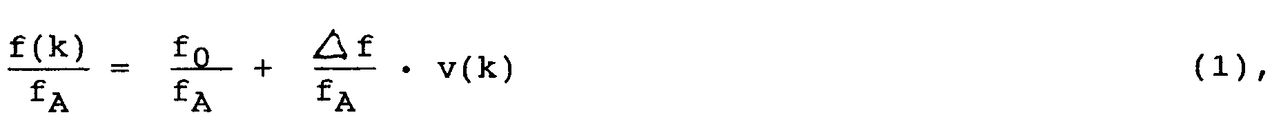
wobei der Term k · T abkürzend durch k, den laufenden Zeit- bzw. Abtastindex, ersetzt wurde. Die Größe f ist der Frequenzhub, der unabhängig von f₀ wählbar ist und der angibt, um wieviel die Momentanfrequenz des modulierenden FM-Signals maximal von der Schwerpunktfrequenz f₀ (das ist die Frequenz des unmodulierten Signals) abweichen kann, wenn ohne Einschränkung der Allgemeinheit
![]()
The signal source Q supplies an analog band-limited signal α · v (t), which is subsequently digitized by an analog-digital converter, or immediately a digital signal ![]()
![]()
![]()
where the term k · T has been abbreviated to k, the current time or sampling index. The variable f is the frequency deviation that can be selected independently of f₀ and specifies by how much the instantaneous frequency of the modulating FM signal can deviate from the center of gravity frequency f₀ (this is the frequency of the unmodulated signal), if without restricting the general public
![]()
Aus (1) folgt die momentane Phase des FM-Signals durch Integration, was im Digitalen durch den idealen Integrator nämlich durch einen rückgekoppelten Akkumulator, realisiert wird mit nachfolgender Multiplikation mit 2π:
Anschließend erfolgt die komplexe Trägererzeugung und -Umsetzung, wobei aus einer Tabelle das komplexwertige FM-Signal
ausgelesen wird. Die komplexwertigen Signale sind in Figur 1 und Figur 2 durch Unterstreichung und in Figur 1 ihre Signalpfade durch Doppel-Striche bzw. Doppel Pfeile und die Bausteine mit komplexwertigen Koeffizienten wie Filter, Tabellen usw. mit doppelter Berandung gekennzeichnet.
j = √![]()
Das FM-Signal g(k) ist idealerweise nicht bandbegrenzt, weshalb es durch ein Filter F mit komplexen Koeffizienten so bandzubegrenzen ist, daß die Systemanforderungen bezüglich Nachbarkanalstörungen eingehalten werden (bei UKW Bandbreite 300 kHz): Das Ergebnis am Filterausgang d(k).
Danach folgt ein Interpolations-Filter CIPF mit komplexen Koeffizienten, welches die Abtastfrequenz fA um den erforderlichen Faktor L erhöht, so daß am Filterausgang nur das gewünschte FM-Siganl y(kT/L) um
![]()
erscheint im Bereich [0,L · fA]` Das bedeutet, daß das komplexe Interpolations-Filter CIPF um fC einen Durchlaßbereich aufweisen und bei bezüglich fA periodischen Spektralanteilen sperren muß.
Wird nun im System nur ein reelles FM-Signal benötigt, so wird lediglich der Realteil oder der Imaginärteil weiter verwendet. Gegebenenfalls kann eine Digital-Analog-Umsetzung erforderlich sein, der dann üblicherweise ein analoges Glättungs-Filter ABP (meistens Tiefpass, aber auch Bandpass) folgt.From (1) follows the instantaneous phase of the FM signal by integration, which is realized in digital form by the ideal integrator, namely by a feedback accumulator, with subsequent multiplication by 2π:
This is followed by complex carrier generation and implementation, with the complex-valued FM signal from a table
is read out. The complex-valued signals are identified in FIG. 1 and FIG. 2 by underlining and in FIG. 1 their signal paths by double dashes or double arrows and the components with complex-valued coefficients such as filters, tables etc. with double borders.
j = √ ![]()
The FM signal g (k) is ideally not band-limited, which is why it must be band-limited by a filter F with complex coefficients in such a way that the system requirements with regard to adjacent channel interference are met (with
This is followed by an interpolation filter CIPF with complex coefficients, which increases the sampling frequency f A by the required factor L, so that only the desired FM signal (kT / L) around the filter output
![]()
appears in the range [0, L · f A ] `This means that the complex interpolation filter CIPF must have a pass band around f C and must block at spectral components that are periodic with respect to f A.
If only a real FM signal is required in the system, only the real part or the imaginary part is used. A digital-to-analog conversion may be required which is then usually followed by an analog smoothing filter ABP (usually low pass, but also band pass).
Die Funktionsweise des beschriebenen FM-Modulators wird nun im Frequenzbereich spektralmäßig erläutert. In den Figuren 2a bis 2e sind die Spektren jeweils mit den entsprechenden Großbuchstaben bezeichnet und beispielhaft Werte für M = 3 und L = 4 angesetzt.
Durch die Fouriertransformation sind Übertragungsfunktion und Impulsantwort bzw. Frequenz- und Zeitbereich miteinander verbunden:
![]()
Am Ausgang des komplexen Oszillators COSZ entsteht das Spektrum G(ejΩ), siehe Figur 2a, das mit dem Filter F auf die zulässige Bandbreite begrenzt wird zu D(ejΩ), siehe Figur 2b. Falls die Mittenfrequenz f₀ = 0 ist, sind Filterfunktion und Spektrum bezüglich f = 0 bzw. bezüglich fA nichtsymmetrisch (Eigenschaften komplexwertiger Signale). Das Interpolations Filter CIPF selektiert den gewünschten Spektralanteil um fC, was möglich ist, da es auf die erhöhte Abtastfrequenz ![]()
Wird nur der Real- oder Imaginärteil weiter verwendet, so ergibt sich das Spektrum Y gemäß Figur 2d. Dieses Spektrum Y ist mit den gezeichneten Spektren symmetrisch sowohl bezüglich f = 0 als auch ![]()
The Fourier transformation connects the transfer function and impulse response or frequency and time range:
![]()
At the output of the complex oscillator COSZ, the spectrum G (e jΩ ) arises , see FIG. 2a, which is limited by the filter F to the permissible bandwidth to D (e jΩ ), see FIG. 2b. If the center frequency is f₀ = 0, the filter function and spectrum are unsymmetrical with respect to f = 0 and f A (properties of complex signals). The interpolation filter CIPF selects the desired spectral component by f C , which is possible because it is based on the increased sampling frequency ![]()
If only the real or imaginary part is used further, the spectrum Y according to FIG. 2d results. This spectrum Y is symmetrical with the spectra drawn both with respect to f = 0 and ![]()
Wie aus den bisherigen Ausführungen und auch aus Figur 2a ersichtlich ist die Bandbreite des FM-Signals g(k) und auch des bandbegrenzten FM-Signals d(k) deutlich größer als die des modulierenden Signals v(k), beispielsweise bei UKW-Stereo 300 kHz zu 60 kHz.
Daher kann das modulierende Digital-Signal v(kT) auch mit niedrigerer Abtastfrequenz fA/P angeliefert werden mit
![]()
wobei P aus Aufwandsgründen, aber nicht zwingend, ganzzahlig gewählt werden sollte.
In diesem Fall ist an beliebiger Stelle zwischen Quelle Q bzw. nach dem Analog-Digital-Umsetzer ADU und dem komplexen Oszillator COSZ die Abtastfrequenz mittels eines Interpolations-Filters oder durch eine Kaskade von mehreren um den Faktor P zu erhöhen.As can be seen from the previous statements and also from FIG. 2a, the bandwidth of the FM signal g (k) and also of the band-limited FM signal d (k) is significantly larger than that of the modulating signal v (k), for example in
Therefore, the modulating digital signal v (kT) can also be delivered with a lower sampling frequency f A / P with
![]()
where P should be chosen as an integer for reasons of effort, but not necessarily.
In this case, the sampling frequency is to be increased by a factor P at any point between source Q or after the analog-digital converter ADU and the complex oscillator COSZ using an interpolation filter or a cascade of several.
Die Multiplikation mit 2π vor dem komplexen Oszillator COSZ gemäß Figur 1 kann entfallen, wenn die Adressen für die COSZ-Tabelle entsprechend normiert werden: Adressraum [0,1] Modulo 1 statt [0,2π] Modulo 2π.
Die Tabelle des komplexen Oszillators COSZ kann in folgenden Varianten aufgebaut sein:
- 1. Zwei Tabellen gleichen Inhalts werden mit unterschiedlichen Adressen angesteuert, wobei die Adressendifferenz

- 2. Es gibt eine gemeinsame Tabelle für Real- und Imaginärteil; diese Tabelle wird für Real- und Imaginärteil sequentiell angesteuert und ausgelesen.
- 3. Es gibt eine Tabelle für Realteil und eine Tabelle für Imaginärteil, beide sind so angeordnet, daß für eine Adresse der Realteil aus der einen und der Imaginärteil aus der anderen Tabelle gleichzeitig und parallel geliefert werden.
The table of the complex oscillator COSZ can be structured in the following variants:
- 1. Two tables of the same content are controlled with different addresses, with the address difference
- 2. There is a common table for real and imaginary parts; this table is controlled and read out sequentially for real and imaginary parts.
- 3. There is a table for the real part and a table for the imaginary part, both are arranged in such a way that for an address the real part from one and the imaginary part from the other table are delivered simultaneously and in parallel.
Die Abtastwerte der komplexen Schwingung gemäß Gl. (3) lassen sich aber auch jeweils aktuell berechnen, z.B. mit Hilfe ausreichend genauer Reihenentwicklungen.The samples of the complex vibration according to Eq. (3) can also be calculated currently, for example with the help of sufficiently precise series developments.
Die Filter mit komplexen Koeffizienten lassen sich im allgemeinsten Fall mit 4 Teilfiltern mit jeweils reellen und paarweise gleichen Koeffizienten realisieren, siehe Figur 6, wodurch der Aufwand ebenfalls erheblich gesenkt wird. Interpolations-Filter, deren Ausgangs-Abtast-Frequenz für verfügbare Bausteine sehr hoch oder zu hoch ist so daß die Realisierung Schwierigkeiten bereitet oder überhaupt nicht möglich ist, lassen sich als sogenannte Polyphasenfilter Netzwerke realisieren, siehe hierzu
Deutsches Patent 40 26 476.9.
Die komplexen Filter F und CIPF können zu einem einzigen komplexwertigen Filter zusammengefaßt werden, was ebenfalls eine Aufwandsverminderung sein kann.In the most general case, the filters with complex coefficients can be implemented with 4 partial filters, each with real and pairwise identical coefficients, see FIG. 6, which also considerably reduces the effort. Interpolation filters, the output sampling frequency of which is very high or too high for available modules, so that implementation is difficult or not possible at all, can be implemented as so-called polyphase filter networks, see here
German patent 40 26 476.9.
The complex filters F and CIPF can be combined into a single complex-valued filter, which can also be a reduction in effort.
Aufgabe der vorliegenden Zusatzanmeldung war es, das Verfahren gemäß der Hauptanmeldung mit noch weniger Aufwand zu ermöglichen.The task of the additional application at hand was to enable the process according to the main application with even less effort.
Die Lösung erfolgt durch die Merkmale des Anspruches 1. vorteilhaft Ausgestaltungen ergeben sich durch die Unteransprüche.The solution is achieved by the features of claim 1. Advantageous refinements result from the subclaims.
Anstelle des komplexen Interpolationsfilters CIPF gemäß Figur 1 wird deshalb gemäß Figur 4 ein Interpolationsfilter in den reellwertigen Signalzweig eingefügt. Im Beispiel der Figur 4 ist dieses reelle Interpolationsfilter IPF mit dem Interpolationsfaktor P direkt vor dem komplexen Oszillator COSZ eingefügt. Es kann aber auch auf dem Signalweg weiter vorne eingefügt sein. Eine weitere Aufwandsverminderung ergibt eine Realisierung des Interpolationsfilters IPF mittels einer Kaskade von hintereinander geschalteten Teilfiltern mit I Interpolationsteilfaktoren Pi, wobei![]()
ist und sinnvollerweise Pi (>1) eine ganze Zahl ist.Instead of the complex interpolation filter CIPF according to FIG. 1, an interpolation filter is therefore inserted into the real-valued signal branch according to FIG. In the example in FIG. 4, this real interpolation filter IPF with the interpolation factor P is inserted directly in front of the complex oscillator COSZ. However, it can also be inserted further up the signal path. A further reduction in expenditure results in the interpolation filter IPF being implemented by means of a cascade of sub-filters connected in series with I interpolation sub-factors P i , where ![]()
and meaningfully P i (> 1) is an integer.
Claims (13)
daß vor oder nach dem rückgekoppelten Phasenakkumulator mittels eines eingefügten Interpolationsfilters die Abtastrate um den Faktor P interpoliert (erhöht) und das NF-Signal gefiltert wird,
daß der Trägeroszillator, der mit der Abtastrate fA arbeitet, ein komplexwertiges FM-Trägersignal g(kT)
erzeugt, wobei die modulatorausgangsseitige Trägerfrequenz des nichtmodulierten Trägers
daß anschließend mittels eines komplexwertigen Filters F eine Bandbegrenzung zu d(kT) bzw. zu y(kT) erfolgt.Method for FM modulation of a digital carrier signal with a digital LF signal by means of a feedback phase accumulator and a carrier oscillator, which generates the sampled values of the modulated FM oscillation or the FM signal under numerical control, characterized in that the modulation signal thus the LF- Signal with which the sampling rate f A / P is sampled with P> 1,
that the sampling rate is interpolated (increased) by a factor P and the LF signal is filtered by an inserted interpolation filter before or after the feedback phase accumulator,
that the carrier oscillator, which operates at the sampling rate f A , a complex-valued FM carrier signal g (kT)
generated, the modulator output side carrier frequency of the non-modulated carrier
that subsequently a band limitation to d (kT) or to y (kT) takes place by means of a complex filter F.
Applications Claiming Priority (2)
| Application Number | Priority Date | Filing Date | Title |
|---|---|---|---|
| DE4320999 | 1993-06-24 | ||
| DE19934320999 DE4320999C2 (en) | 1993-06-24 | 1993-06-24 | Frequency modulation method |
Publications (3)
| Publication Number | Publication Date |
|---|---|
| EP0631376A2 true EP0631376A2 (en) | 1994-12-28 |
| EP0631376A3 EP0631376A3 (en) | 1995-11-08 |
| EP0631376B1 EP0631376B1 (en) | 1998-12-16 |
Family
ID=6491121
Family Applications (1)
| Application Number | Title | Priority Date | Filing Date |
|---|---|---|---|
| EP94108901A Expired - Lifetime EP0631376B1 (en) | 1993-06-24 | 1994-06-10 | Method for frequency modulation |
Country Status (4)
| Country | Link |
|---|---|
| EP (1) | EP0631376B1 (en) |
| AT (1) | ATE174733T1 (en) |
| DE (1) | DE59407477D1 (en) |
| ES (1) | ES2127849T3 (en) |
Cited By (1)
| Publication number | Priority date | Publication date | Assignee | Title |
|---|---|---|---|---|
| FR2810814A1 (en) * | 2000-06-26 | 2001-12-28 | St Microelectronics Sa | Radio frequency sound/video digital sound transmission having modulator with bits first frequency sampled and phase lock loop/adder interval register providing sinusoidal filter bit coded signal. |
Citations (5)
| Publication number | Priority date | Publication date | Assignee | Title |
|---|---|---|---|---|
| JPS6262603A (en) * | 1985-09-12 | 1987-03-19 | Matsushita Electric Ind Co Ltd | Fm modulator device for digital processing |
| EP0419680A1 (en) * | 1989-04-07 | 1991-04-03 | SHARP Corporation | Frequency modulator |
| DE4026476A1 (en) * | 1990-08-22 | 1992-03-05 | Ant Nachrichtentech | Complex polyphase filter network for sampling rate change - groups in each branch folding prods. of real and imaginary parts of input signal for interpolation of decimation |
| US5111163A (en) * | 1991-05-06 | 1992-05-05 | Hughes Aircraft Company | Digital FM modulator |
| EP0508661A1 (en) * | 1991-04-11 | 1992-10-14 | Harris Corporation | An FM modulator circuit having separate modulation and channel signal paths |
-
1994
- 1994-06-10 AT AT94108901T patent/ATE174733T1/en not_active IP Right Cessation
- 1994-06-10 EP EP94108901A patent/EP0631376B1/en not_active Expired - Lifetime
- 1994-06-10 ES ES94108901T patent/ES2127849T3/en not_active Expired - Lifetime
- 1994-06-10 DE DE59407477T patent/DE59407477D1/en not_active Expired - Fee Related
Patent Citations (5)
| Publication number | Priority date | Publication date | Assignee | Title |
|---|---|---|---|---|
| JPS6262603A (en) * | 1985-09-12 | 1987-03-19 | Matsushita Electric Ind Co Ltd | Fm modulator device for digital processing |
| EP0419680A1 (en) * | 1989-04-07 | 1991-04-03 | SHARP Corporation | Frequency modulator |
| DE4026476A1 (en) * | 1990-08-22 | 1992-03-05 | Ant Nachrichtentech | Complex polyphase filter network for sampling rate change - groups in each branch folding prods. of real and imaginary parts of input signal for interpolation of decimation |
| EP0508661A1 (en) * | 1991-04-11 | 1992-10-14 | Harris Corporation | An FM modulator circuit having separate modulation and channel signal paths |
| US5111163A (en) * | 1991-05-06 | 1992-05-05 | Hughes Aircraft Company | Digital FM modulator |
Non-Patent Citations (1)
| Title |
|---|
| PATENT ABSTRACTS OF JAPAN vol. 11 no. 249 (E-532) ,13.August 1987 & JP-A-62 062603 (MATSUSHITA ELECTRIC IND CO) 19.März 1987, * |
Cited By (2)
| Publication number | Priority date | Publication date | Assignee | Title |
|---|---|---|---|---|
| FR2810814A1 (en) * | 2000-06-26 | 2001-12-28 | St Microelectronics Sa | Radio frequency sound/video digital sound transmission having modulator with bits first frequency sampled and phase lock loop/adder interval register providing sinusoidal filter bit coded signal. |
| US6587011B2 (en) | 2000-06-26 | 2003-07-01 | Stmicroelectronics S.A. | Low cost digital FM modulator |
Also Published As
| Publication number | Publication date |
|---|---|
| EP0631376B1 (en) | 1998-12-16 |
| EP0631376A3 (en) | 1995-11-08 |
| ES2127849T3 (en) | 1999-05-01 |
| DE59407477D1 (en) | 1999-01-28 |
| ATE174733T1 (en) | 1999-01-15 |
Similar Documents
| Publication | Publication Date | Title |
|---|---|---|
| EP0084876A2 (en) | Demodulator arrangement for signals which are frequency-modulated on a carrier wave | |
| DE936097C (en) | Receiving arrangement for a message ambiguously representing electrical signals | |
| DE2223940C3 (en) | N-path filter | |
| DE2703566B2 (en) | Frequency modulation system | |
| EP0261479A2 (en) | Optical heterodyne receiver | |
| DE69535211T2 (en) | DEVICE FOR CONTINUOUS PHASE MODULATION WITH FREQUENCY SYNTHETIZER WITH LASER REPLACEMENT | |
| DE2852718C2 (en) | Method for generating a wave with a line spectrum | |
| DE2932961A1 (en) | METHOD AND CIRCUIT ARRANGEMENT FOR RECOVERING THE CARRIER FREQUENCY FROM A MODULATED ELECTRICAL INPUT SIGNAL | |
| DE2720649C2 (en) | ||
| DE2201391C3 (en) | Arrangement for frequency conversion of analog signals | |
| EP0631376B1 (en) | Method for frequency modulation | |
| DE3733967C2 (en) | ||
| EP0631378B1 (en) | Frequency modulation method | |
| EP0632576B1 (en) | Frequency modulation method | |
| EP0651526A2 (en) | Method for processing a digital frequencymultiplex signal | |
| EP0631377B1 (en) | Method for frequency modulation | |
| DE4320996C2 (en) | Frequency modulation method | |
| DE4320999A1 (en) | Frequency modulation method | |
| DE4244144C1 (en) | Demodulating FM signals esp. in ultra short wave range - sampling received signal and passing sampled signal through band filter with complex value coeffts. | |
| DE4320997C2 (en) | Frequency modulation method | |
| EP0428765B1 (en) | Method and device for frequency modulation | |
| DE4321000A1 (en) | Frequency modulation method | |
| DE2215209A1 (en) | Residual sideband signal generation | |
| DE3303516A1 (en) | METHOD AND DEVICE FOR FREQUENCY SHIFTING A DIGITAL INPUT SIGNAL | |
| DE2363214B2 (en) | Arrangement for phase modulation |
Legal Events
| Date | Code | Title | Description |
|---|---|---|---|
| PUAI | Public reference made under article 153(3) epc to a published international application that has entered the european phase |
Free format text: ORIGINAL CODE: 0009012 |
|
| AK | Designated contracting states |
Kind code of ref document: A2 Designated state(s): AT CH DE ES FR GB IT LI NL |
|
| PUAL | Search report despatched |
Free format text: ORIGINAL CODE: 0009013 |
|
| AK | Designated contracting states |
Kind code of ref document: A3 Designated state(s): AT CH DE ES FR GB IT LI NL |
|
| RAP1 | Party data changed (applicant data changed or rights of an application transferred) |
Owner name: ROBERT BOSCH GMBH |
|
| 17P | Request for examination filed |
Effective date: 19960508 |
|
| GRAG | Despatch of communication of intention to grant |
Free format text: ORIGINAL CODE: EPIDOS AGRA |
|
| 17Q | First examination report despatched |
Effective date: 19980225 |
|
| GRAG | Despatch of communication of intention to grant |
Free format text: ORIGINAL CODE: EPIDOS AGRA |
|
| GRAH | Despatch of communication of intention to grant a patent |
Free format text: ORIGINAL CODE: EPIDOS IGRA |
|
| GRAH | Despatch of communication of intention to grant a patent |
Free format text: ORIGINAL CODE: EPIDOS IGRA |
|
| GRAA | (expected) grant |
Free format text: ORIGINAL CODE: 0009210 |
|
| AK | Designated contracting states |
Kind code of ref document: B1 Designated state(s): AT CH DE ES FR GB IT LI NL |
|
| REF | Corresponds to: |
Ref document number: 174733 Country of ref document: AT Date of ref document: 19990115 Kind code of ref document: T |
|
| REG | Reference to a national code |
Ref country code: CH Ref legal event code: NV Representative=s name: SCINTILLA AG, DIREKTION Ref country code: CH Ref legal event code: EP |
|
| REF | Corresponds to: |
Ref document number: 59407477 Country of ref document: DE Date of ref document: 19990128 |
|
| ET | Fr: translation filed | ||
| ITF | It: translation for a ep patent filed |
Owner name: STUDIO JAUMANN P. & C. S.N.C. |
|
| GBT | Gb: translation of ep patent filed (gb section 77(6)(a)/1977) |
Effective date: 19990223 |
|
| REG | Reference to a national code |
Ref country code: ES Ref legal event code: FG2A Ref document number: 2127849 Country of ref document: ES Kind code of ref document: T3 |
|
| PLBE | No opposition filed within time limit |
Free format text: ORIGINAL CODE: 0009261 |
|
| STAA | Information on the status of an ep patent application or granted ep patent |
Free format text: STATUS: NO OPPOSITION FILED WITHIN TIME LIMIT |
|
| 26N | No opposition filed | ||
| PGFP | Annual fee paid to national office [announced via postgrant information from national office to epo] |
Ref country code: GB Payment date: 20000719 Year of fee payment: 7 |
|
| PGFP | Annual fee paid to national office [announced via postgrant information from national office to epo] |
Ref country code: DE Payment date: 20010605 Year of fee payment: 8 |
|
| PG25 | Lapsed in a contracting state [announced via postgrant information from national office to epo] |
Ref country code: GB Free format text: LAPSE BECAUSE OF NON-PAYMENT OF DUE FEES Effective date: 20010610 |
|
| PGFP | Annual fee paid to national office [announced via postgrant information from national office to epo] |
Ref country code: FR Payment date: 20010622 Year of fee payment: 8 |
|
| PGFP | Annual fee paid to national office [announced via postgrant information from national office to epo] |
Ref country code: AT Payment date: 20010625 Year of fee payment: 8 |
|
| PGFP | Annual fee paid to national office [announced via postgrant information from national office to epo] |
Ref country code: NL Payment date: 20010626 Year of fee payment: 8 Ref country code: CH Payment date: 20010626 Year of fee payment: 8 |
|
| PGFP | Annual fee paid to national office [announced via postgrant information from national office to epo] |
Ref country code: ES Payment date: 20010629 Year of fee payment: 8 |
|
| GBPC | Gb: european patent ceased through non-payment of renewal fee |
Effective date: 20010610 |
|
| PG25 | Lapsed in a contracting state [announced via postgrant information from national office to epo] |
Ref country code: AT Free format text: LAPSE BECAUSE OF NON-PAYMENT OF DUE FEES Effective date: 20020610 |
|
| PG25 | Lapsed in a contracting state [announced via postgrant information from national office to epo] |
Ref country code: ES Free format text: LAPSE BECAUSE OF NON-PAYMENT OF DUE FEES Effective date: 20020611 |
|
| PG25 | Lapsed in a contracting state [announced via postgrant information from national office to epo] |
Ref country code: LI Free format text: LAPSE BECAUSE OF NON-PAYMENT OF DUE FEES Effective date: 20020630 Ref country code: CH Free format text: LAPSE BECAUSE OF NON-PAYMENT OF DUE FEES Effective date: 20020630 |
|
| PG25 | Lapsed in a contracting state [announced via postgrant information from national office to epo] |
Ref country code: NL Free format text: LAPSE BECAUSE OF NON-PAYMENT OF DUE FEES Effective date: 20030101 Ref country code: DE Free format text: LAPSE BECAUSE OF NON-PAYMENT OF DUE FEES Effective date: 20030101 |
|
| REG | Reference to a national code |
Ref country code: CH Ref legal event code: PL |
|
| PG25 | Lapsed in a contracting state [announced via postgrant information from national office to epo] |
Ref country code: FR Free format text: LAPSE BECAUSE OF NON-PAYMENT OF DUE FEES Effective date: 20030228 |
|
| NLV4 | Nl: lapsed or anulled due to non-payment of the annual fee |
Effective date: 20030101 |
|
| REG | Reference to a national code |
Ref country code: FR Ref legal event code: ST |
|
| REG | Reference to a national code |
Ref country code: ES Ref legal event code: FD2A Effective date: 20030711 |
|
| PG25 | Lapsed in a contracting state [announced via postgrant information from national office to epo] |
Ref country code: IT Free format text: LAPSE BECAUSE OF NON-PAYMENT OF DUE FEES;WARNING: LAPSES OF ITALIAN PATENTS WITH EFFECTIVE DATE BEFORE 2007 MAY HAVE OCCURRED AT ANY TIME BEFORE 2007. THE CORRECT EFFECTIVE DATE MAY BE DIFFERENT FROM THE ONE RECORDED. Effective date: 20050610 |