EP0631346B1 - Elektrischer Verbinder - Google Patents
Elektrischer Verbinder Download PDFInfo
- Publication number
- EP0631346B1 EP0631346B1 EP93304880A EP93304880A EP0631346B1 EP 0631346 B1 EP0631346 B1 EP 0631346B1 EP 93304880 A EP93304880 A EP 93304880A EP 93304880 A EP93304880 A EP 93304880A EP 0631346 B1 EP0631346 B1 EP 0631346B1
- Authority
- EP
- European Patent Office
- Prior art keywords
- cable
- connector
- connector member
- cable supporting
- supporting portion
- Prior art date
- Legal status (The legal status is an assumption and is not a legal conclusion. Google has not performed a legal analysis and makes no representation as to the accuracy of the status listed.)
- Expired - Lifetime
Links
- 238000005476 soldering Methods 0.000 claims 1
- 238000005452 bending Methods 0.000 description 1
- 230000006835 compression Effects 0.000 description 1
- 238000007906 compression Methods 0.000 description 1
- 210000003811 finger Anatomy 0.000 description 1
- 238000000034 method Methods 0.000 description 1
- 210000004935 right thumb Anatomy 0.000 description 1
Images

Classifications
-
- H—ELECTRICITY
- H01—ELECTRIC ELEMENTS
- H01R—ELECTRICALLY-CONDUCTIVE CONNECTIONS; STRUCTURAL ASSOCIATIONS OF A PLURALITY OF MUTUALLY-INSULATED ELECTRICAL CONNECTING ELEMENTS; COUPLING DEVICES; CURRENT COLLECTORS
- H01R13/00—Details of coupling devices of the kinds covered by groups H01R12/70 or H01R24/00 - H01R33/00
- H01R13/58—Means for relieving strain on wire connection, e.g. cord grip, for avoiding loosening of connections between wires and terminals within a coupling device terminating a cable
- H01R13/59—Threaded ferrule or bolt operating in a direction parallel to the cable or wire
Definitions
- This invention relates to electrical connectors, and more particularly to microphone connectors.
- DE-A-2 647 043 discloses an electrical connector in which a connector housing is threadedly engaged with a pressure component located in a generally axially extending opening within a connector member, so as to pull the pressure component against an inclined surface of the connector member and exert a retaining force on a cable by virtue of a wedging action. This has certain disadvantages.
- the present invention provides an electrical connector comprising a tubular connector member having a generally axially extending opening therein, a connector housing, terminal means located in use within said connector member for connecting to a cable located within said generally axial opening, and cable supporting means located in use within said generally axial opening of said connector member, characterised in that said connector housing is threadedly engageable with said connector member at a cable receiving end thereof being an end of said connector member which receives a said cable, said cable supporting means includes an annular or part annular wall portion for locating about a said cable and an elongate cable supporting portion extending from said wall portion towards said cable receiving end of said connector member, said elongate cable supporting portion turning radially inwardly at the end thereof which is nearest said cable receiving end of said connector member, the arrangement being such that when said connector housing is threadedly engaged with said connector member and tightened, said elongate cable supporting portion is pressed inwards by an inner surface of said connector housing so as to pinch and thereby secure a said
- the cable supporting means and the terminal means comprise separate members which are removably located within the generally axially extending opening of the tubular connector member, the cable supporting member being located axially closest to the end of the connector member which receives the cable and with which the housing is engaged.
- the terminal means may comprise any suitable plug or terminal carrier such as may be used in a microphone or electrical connector.
- the wall portion of the cable supporting member preferably includes locating means such as a protrusion for engaging with a groove in the inner wall of the connector member to prevent rotation.
- the wall portion acts to guide the cable through to the terminal means, for example comprising a closed annulus or more preferably an annular ring having an axial slit therein to accommodate variations in cable diameter.
- a portion of the terminal means may also co-operate with a part annular wall portion of the cable supporting means to guide the cable within said generally axial opening.
- the cable supporting portion of such a cable supporting member extends axially from the wall portion, and turns radially inwardly towards a free end.
- the inwardly extending portion is curved, the curvature preferably increasing towards the free end so that at its free end the cable supporting member extends substantially completely radially to define a generally circumferential ridge at the free end, upon which the cable is supported.
- the inner surface of the cable supporting portion is curved (or otherwise suitably shaped) to conform substantially to the outer surface of a said cable.
- the cable supporting member pinches the cable against the housing, preferably being resiliently compressed and/or deflected to a small degree.
- two protrusions formed at the circumferential ends of a supporting ridge as previously described dig into the cable to some degree to assist in gripping and retaining the cable within the connector.
- the cable supporting member bends the cable to hold it securely within the connector. It will be seen in certain embodiments described hereinafter that a cable is guided through the opening in the outer end of a connector housing, over the end of a cable supporting member, along the length of the supporting member and through an annular portion to said terminal means.
- the housing preferably has an internal thread which engages with an external thread on the connector member.
- An annular ring may be provided inside the housing for pressing against the cable, in some embodiments having a tapered section for pressing against the cable.
- the connector member has a holding portion towards one end, a smooth intermediate portion and an externally threaded portion towards the other end for engagement with the connector housing.
- the intermediate smooth portion is preferably longer than said externally threaded portion.
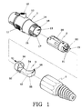
- Figure 1 is an exploded perspective view of a first embodiment of a microphone connector in accordance with the present invention.
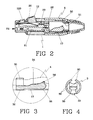
- Figure 2 is a cross-sectional view of the first embodiment of the microphone connector shown in Fig. 1;
- Figure 3 is a magnified cross-sectional view of a cable pincher in the first embodiment of microphone connector shown in Fig. 1;
- Figure 4 is a rear view of the cable pincher in the first embodiment of microphone connector shown in Fig. 1;
- Figure 5 is an exploded perspective view of a second embodiment of microphone connector in accordance with the present invention.
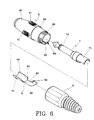
- Figure 6 is an exploded perspective view of a third embodiment of the microphone connector in accordance with the present invention.
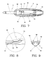
- Figure 7 is a cross-sectional view of the third embodiment of microphone connector shown in Figure 6;
- Figure 8 is a magnified cross-sectional view of a cable pincher of the third embodiment of microphone connector shown in Fig. 6;
- Figure 9 is a rear view of the cable pincher of the third embodiment of microphone connector.
- a first embodiment of a female microphone connector in accordance with the present invention comprises a connector member 1, a terminal carrier 2, a cable support member or cable pincher 3, and a connector housing 5 as main components.
- the connector member 1 is generally cylindrically shaped, having a proximal hand holding surface portion 10 with two opposite grips 11,11 for a user to grip the connector, an intermediate smooth portion 14 and a distal male-threaded portion 15.
- An axially extending through hole 13 is provided for receiving the terminal carrier 2 and the cable pincher 3 therein.
- the connector member 1 also has a push button 12 on the holding surface portion 10 and a front end 120 for assembling with the connector housing 5.
- the intermediate smooth portion 14 is relatively long and the distal male-threaded portion 15 is relatively short so that the connector member 1 can be assembled with the connector housing 5 with little force.
- Two opposing axially extending grooves 16,17 are provided in an inner surface of the hole 13 for aligning the terminal carrier 2 and the cable pincher 3 unrotatably in the hole 13.
- the terminal carrier 2 is fitted in the through hole 13 of the connector member 1. It has a plate spring 20 fixed axially on its surface, two terminals 21,21 to fit in terminal holes 24,24, a negative terminal 22 fixed on the carrier body with a bolt 23, and the end of each terminal is soldered with a wire of the cable 4.
- the cable pincher 3 has an annular wall 30 with a slot 31 therein, which slot 31 allows pinching of cables of various sizes.
- the cable pincher 3 is further provided with an engaging block 32 on the bottom of the wall 30 to engage with the groove 17 of the connector member 1, a supporting portion 33 with an upper recessed and curved surface 34 and an upwardly curved end 35 and two pinching points 36,36 on the curve end 35. Therefore, after the cable 4 is put through the pincher 3, the connector housing 5 is screwed on to the connector member 1, by engaging the female-thread 50 with the male thread 15.
- the cable 4 can be bent up a little by a compact ring 51 in the connector housing 5, as shown in Fig. 3.
- the pinching points 36,36 stick into the outer surface of the cable 4, which is then difficult to pull off.
- Fig. 5 shows a second embodiment of a male microphone connector according to the present invention, which comprises a connector member 1', a terminal carrier 2', a cable pincher 3 having the same structure as that of the first embodiment, and a connector housing 5 of the same structure as that of the first embodiment.
- the connector member 1' is cylindrical, having a proximal hand holding surface portion 10' with two opposite grips 11',11', an intermediate smooth portion 13', a distal male-threaded portion 14', an axially extending through hole 12' and two lengthwise grooves 14',15' in an inner surface for the terminal carrier 2' and the cable pincher 3 to fit unrotatably therein.
- Two terminals 20' are fixed with the terminal carrier 2' and the number of the terminals should be the same as that of the connector member 1'.
- Figs. 6-8 show a third embodiment of a plug-in microphone connector according to the present invention, which comprises a connector member 6, a plug 7, a cable pincher 8 and a connector housing 9.
- the connector member 6 has a long proximal hand holding portion 60 with 4 curved grips 61 for fingers to grip thereon, an intermediate smooth portion 62 and a distal male-threaded portion 63.
- An axially extending through hole 64 is provided for receiving an inserting portion 70 of the plug 7, and a lengthwise groove 65 for locating the plug 7 against rotation therein.
- the plug 7 has an inserting portion 70 and an inner end of semi-circular cross-section forming a cylindrical wall together with a semi-cylindrical wall 80 of the cable pincher 8, for pinching a cable therein.
- the cable pincher 8 has a semi-cylindrical wall 80, a locating block 81 underneath for fitting with the groove 65 of the connector member 6, a supporting portion 82 having a recessed and curved surface 83 and two pinching points 84 on an outer end, and an upwardly curved lower surface 85.
- the connector housing 9 has a female-threaded portion to engage the male-threaded portion 63 of the connector member 6, a compact ring 90 urging a cable against the cable pincher 8 and letting the pinching points 84 stick in the cable 4, for attaining the purpose of securely pinching the cable 4.
- an electrical or microphone connector with a cable pincher shaped to conform to a connector member; and there is provided a cable pincher having a pinching block with a shaped and recessed upper surface for a cable to lie on, bending up sharply for tightly pinching a cable; and there is provided a pinching block having two pinching points on the outer end of the upper surface for sticking in the surface of a cable to reinforce pinching of the cable.
Landscapes
- Details Of Connecting Devices For Male And Female Coupling (AREA)
Claims (10)
- Elektrischer Verbinder, umfassend ein rohrartiges Verbinderelement (1; 1'; 6) mit einer allgemein axial verlaufenden Öffnung (13; 12'; 64) darin, ein Verbindergehäuse (5; 9), gebrauchsmäßig in dem Verbinderelement (1; 1'; 6) angeordnete Anschlußmittel (2; 2'; 7) zur Verbindung mit einem in der allgemein axialen Öffnung (13; 12'; 64) angeordneten Kabel sowie gebrauchsmäßig in der allgemein axialen Öffnung (13; 12'; 64) des Verbinderelements (1; 1'; 6) angeordnete Kabeltragemittel (3; 8),
dadurch gekennzeichnet, daß das Verbindergehäuse (5; 9) mit dem Verbinderelement (1; 1'; 6) an einem Kabelaufnahmeende desselben in Gewindeeingriff bringbar ist, welches Kabelaufnahmeende ein das Kabel aufnehmendes Ende des Verbinderelements (1; 1'; 6) ist, daß die Kabeltragemittel einen ring- oder teilringförmigen Wandabschnitt (30; 80) zur Anordnung um das Kabel und einen länglichen Kabeltrageabschnitt (34; 82) umfassen, der von dem Wandabschnitt (30; 80) zu dem Kabelaufnahmeende des Verbinderelements (1; 1'; 6) verläuft, wobei der längliche Kabeltrageabschnitt (34; 82) an seinem dem Kabelaufnahmeende des Verbinderelements (1; 1'; 6) nächsten Ende nach radial einwärts gerichtet ist, wobei die Anordnung derart ist, daß dann, wenn das Verbindergehäuse (5; 9) in Gewindeeingriff mit dem Verbinderelement (1; 1'; 6) steht und festgezogen ist, der längliche Kabeltrageabschnitt (34; 82) durch eine Innenfläche des Verbindergehäuses (5; 9) nach innen gedrückt ist, um das Kabel einzuklemmen und dadurch in dem Verbinder zu sichern. - Elektrischer Verbinder nach Anspruch 1, bei dem der Kabeltrageabschnitt (34; 82) der Kabeltragemittel (3; 8) elastisch ist.
- Elektrischer Verbinder nach Anspruch 1 oder 2, bei dem der Kabeltrageabschnitt (34; 82) der Kabeltragemittel (3; 8) dazu ausgebildet ist, sich in das Kabel (4) einzudrücken und es dadurch zu greifen.
- Elektrischer Verbinder nach einem der vorhergehenden Ansprüche, bei dem die Kabeltragemittel (3; 8) zum Biegen des Kabels (4) mit dem Verbindergehäuse (5; 9) zusammenwirken.
- Elektrischer Verbinder nach einem der vorhergehenden Ansprüche, bei dem der Kabeltrageabschnitt (34; 82) eine allgemein an die Außenfläche eines Kabels (4) formangepaßte gekrümmte Innenfläche aufweist.
- Elektrischer Verbinder nach Anspruch 5, bei dem an dem Ende des Kabeltrageabschnitts (34; 82) zwei in Umfangsrichtung im Abstand voneinander angeordnete Vorsprünge zum Drücken in das Kabel (4) ausgebildet sind.
- Elektrischer Verbinder nach einem der vorhergehenden Ansprüche, bei dem der Wandabschnitt (30) einen Ring (30) zum Umschließen des Kabels (4) sowie einen axialen Schlitz (31) zur Anpassung an verschiedene Kabeldurchmesser umfaßt.
- Elektrischer Verbinder nach einem der Ansprüche 1 bis 6, bei dem der Wandabschnitt (80) mit einem in Umfangsrichtung verlaufenden Abschnitt der Anschlußmittel (7) zusammenwirkt, um das Kabel (4) zu umschließen.
- Elektrischer Verbinder nach einem der vorhergehenden Ansprüche, der einen Mikrophonverbinder bildet.
- Mikrophonverbinder mit einem elektrischen Verbinder nach Anspruch 1, bei dem:das Verbinderelement (1; 1'; 6) einen proximalen Handhalteabschnitt (10; 10'; 60), einen glatten Zwischenabschnitt (14; 13'; 62) sowie einen distalen Außengewindeabschnitt (15; 14'; 63) zum Eingriff mit einem Innengewindeabschnitt (50) des Verbindergehäuses (5; 9) aufweist,die Anschlußmittel einen Anschlußträger (2, 2') umfassen, der in die allgemein axial verlaufende Öffnung (13; 12'; 64) des Verbinderelements (1; 1'; 6) paßt und eine Blattfeder (20) an einer längs verlaufenden Fläche sowie eine Mehrzahl von Anschlußlöchern zum Durchgang von Anschlüssen (21, 22; 20'; 70) aufweist, wobei die Anschlüsse (21, 22; 20'; 70) ein Ende zum Anlöten an Drähte des Kabels (4) aufweisen,das Verbindergehäuse (5; 9) einen Innengewindeabschnitt (50) zum Eingriff mit dem Außengewindeabschnitt (15; 14'; 63) des Verbinderelements (1; 1'; 6) sowie einen Kompaktring (51; 90) an einer Innenfläche aufweist,die Kabeltragemittel (3; 8) eine Ringwand (30; 80) mit einem Schlitz (31) aufweisen, um Kabel (4) verschiedener Größen durch die Ringöffnung hindurch aufnehmen zu können, wobei der in Längsrichtung von der Wand (30; 80) ausgehende Kabeltrageabschnitt (34; 82) eine vertiefte und gekrümmte Fläche sowie zwei Eindrückpunkte (36; 84) an dem dem Kabelaufnahmeende des Verbinderelements (1; 1'; 6) nächsten Ende aufweist und sich die Innen- und Außenflächen (34, 35; 83, 85) allmählich radial einwärts zu dem Ende krümmen undwobei der Kompaktring (51; 90) in dem Verbindergehäuse (5; 9) den gekrümmten Endabschnitt (34; 83) des Kabeltrageabschnitts (34; 82) komprimiert, nachdem das Verbindergehäuse (5; 9) mit dem Verbinderelement (1; 1'; 6) kombiniert ist, wobei sich die Eindrückpunkte (36; 84) des Kabeltrageabschnitts (34; 82) dann in die Oberfläche eines Kabels (4) eindrücken und das Kabel (4) gezwungen ist, sich der Krümmung des Kabeltrageabschnitts (34; 82) entsprechend zu biegen, so daß der Kabeltrageabschnitt (34; 82) ausreichend in das Kabel (4) eindrücken kann, um das Kabel (4) im wesentlichen unbeweglich und unlösbar zu machen.
Priority Applications (5)
| Application Number | Priority Date | Filing Date | Title |
|---|---|---|---|
| EP93304880A EP0631346B1 (de) | 1993-04-19 | 1993-06-23 | Elektrischer Verbinder |
| DE1993615328 DE69315328T2 (de) | 1993-06-23 | 1993-06-23 | Elektrischer Verbinder |
| AT93304880T ATE160469T1 (de) | 1993-06-23 | 1993-06-23 | Elektrischer verbinder |
| US08/151,232 US5368502A (en) | 1993-04-19 | 1993-11-12 | Plug - in microphone connector |
| US08/151,230 US5362252A (en) | 1993-04-19 | 1993-11-12 | Microphone connector |
Applications Claiming Priority (2)
| Application Number | Priority Date | Filing Date | Title |
|---|---|---|---|
| US08/047,953 US5336108A (en) | 1991-03-27 | 1993-04-19 | Microphone connector |
| EP93304880A EP0631346B1 (de) | 1993-04-19 | 1993-06-23 | Elektrischer Verbinder |
Publications (2)
| Publication Number | Publication Date |
|---|---|
| EP0631346A1 EP0631346A1 (de) | 1994-12-28 |
| EP0631346B1 true EP0631346B1 (de) | 1997-11-19 |
Family
ID=26134351
Family Applications (1)
| Application Number | Title | Priority Date | Filing Date |
|---|---|---|---|
| EP93304880A Expired - Lifetime EP0631346B1 (de) | 1993-04-19 | 1993-06-23 | Elektrischer Verbinder |
Country Status (2)
| Country | Link |
|---|---|
| US (2) | US5368502A (de) |
| EP (1) | EP0631346B1 (de) |
Families Citing this family (4)
| Publication number | Priority date | Publication date | Assignee | Title |
|---|---|---|---|---|
| US6116945A (en) * | 1997-12-30 | 2000-09-12 | The Whitaker Corporation | Microphone connector assembly |
| US6626704B1 (en) * | 2002-04-25 | 2003-09-30 | Daniel Pikel | Acoustic adapter device |
| CN103457097B (zh) * | 2012-05-31 | 2015-11-25 | 富士康(昆山)电脑接插件有限公司 | 线缆连接器 |
| USD1089122S1 (en) * | 2023-06-30 | 2025-08-19 | Karim Messadek | XLR connector |
Family Cites Families (7)
| Publication number | Priority date | Publication date | Assignee | Title |
|---|---|---|---|---|
| GB447987A (en) * | 1934-12-17 | 1936-05-29 | Bulpitt & Sons Ltd | Improvements in cord grips for electrical appliances |
| GB876293A (en) * | 1958-01-27 | 1961-08-30 | Rendar Instr Ltd | Improvements in and relating to electrical connector devices |
| US3989340A (en) * | 1975-04-29 | 1976-11-02 | General Electric Company | Insulator ramp clamp for connectors |
| AT343200B (de) * | 1975-10-23 | 1978-05-10 | Neutrik Ag | Gehause oder gehauseteil fur elektrische oder elektrisch betriebene gerate und kontaktelemente |
| AT376525B (de) * | 1982-06-08 | 1984-11-26 | Neutrik Ag | Elektrische steckverbindung mit mindestens zwei zu paarenden steckerteilen |
| FR2568418B1 (fr) * | 1984-07-30 | 1987-07-03 | Borloz Didier | Connecteur electrique multipolaire. |
| GB2256322B (en) * | 1991-05-30 | 1995-05-24 | Shinagawa Shoko Co Ltd | Cable holder |
-
1993
- 1993-06-23 EP EP93304880A patent/EP0631346B1/de not_active Expired - Lifetime
- 1993-11-12 US US08/151,232 patent/US5368502A/en not_active Expired - Fee Related
- 1993-11-12 US US08/151,230 patent/US5362252A/en not_active Expired - Fee Related
Also Published As
| Publication number | Publication date |
|---|---|
| US5368502A (en) | 1994-11-29 |
| EP0631346A1 (de) | 1994-12-28 |
| US5362252A (en) | 1994-11-08 |
Similar Documents
| Publication | Publication Date | Title |
|---|---|---|
| US5072072A (en) | Electrical connector for liquidtight conduit | |
| US6682355B1 (en) | Electrical fitting for easy snap engagement of cables | |
| US5051541A (en) | Plastic electrical connector for liquidtight conduit | |
| US6335488B1 (en) | Snap in cable connector | |
| EP0227390B1 (de) | Drehbare elektrische Verbindungsvorrichtung | |
| US4801833A (en) | Motor end cap | |
| US6523231B1 (en) | Power cord clip | |
| US5347689A (en) | Reusable bolt seal | |
| US4834677A (en) | Male and/or female electrical connectors | |
| US7484993B2 (en) | Ethernet cable connector and methods of use thereof | |
| US4632488A (en) | Cord strain relief device | |
| KR20120030070A (ko) | 미처리 케이블 단부 동축 커넥터 | |
| US20070093128A1 (en) | Coaxial cable connector having collar with cable gripping features | |
| CA2137526A1 (en) | Connectors | |
| US5905230A (en) | Self tapping screw for use with an electrical connector | |
| EP0631346B1 (de) | Elektrischer Verbinder | |
| US4925399A (en) | Cord clip | |
| EP0913900B1 (de) | Kabelklemmvorrichtung | |
| US6547600B2 (en) | Engaging structure for electrical wires of a plug | |
| CN1297596A (zh) | 无螺纹的插塞式连接器 | |
| US4781617A (en) | Cable connector arrangement to accommodate multiple cable sizes | |
| US5336108A (en) | Microphone connector | |
| WO1993017469A1 (en) | Improvements in cable grips | |
| EP0465261A2 (de) | Steckverbinder für Mehrleiterkabel | |
| US4390227A (en) | Cord grip for electrical wiring connector devices |
Legal Events
| Date | Code | Title | Description |
|---|---|---|---|
| PUAI | Public reference made under article 153(3) epc to a published international application that has entered the european phase |
Free format text: ORIGINAL CODE: 0009012 |
|
| AK | Designated contracting states |
Kind code of ref document: A1 Designated state(s): AT BE CH DE DK ES FR GB GR IE IT LI LU MC NL PT SE |
|
| 17P | Request for examination filed |
Effective date: 19950619 |
|
| 17Q | First examination report despatched |
Effective date: 19960201 |
|
| GRAG | Despatch of communication of intention to grant |
Free format text: ORIGINAL CODE: EPIDOS AGRA |
|
| GRAH | Despatch of communication of intention to grant a patent |
Free format text: ORIGINAL CODE: EPIDOS IGRA |
|
| GRAH | Despatch of communication of intention to grant a patent |
Free format text: ORIGINAL CODE: EPIDOS IGRA |
|
| GRAA | (expected) grant |
Free format text: ORIGINAL CODE: 0009210 |
|
| AK | Designated contracting states |
Kind code of ref document: B1 Designated state(s): AT BE CH DE DK ES FR GB GR IE IT LI LU MC NL PT SE |
|
| PG25 | Lapsed in a contracting state [announced via postgrant information from national office to epo] |
Ref country code: NL Free format text: LAPSE BECAUSE OF FAILURE TO SUBMIT A TRANSLATION OF THE DESCRIPTION OR TO PAY THE FEE WITHIN THE PRESCRIBED TIME-LIMIT Effective date: 19971119 Ref country code: IT Free format text: LAPSE BECAUSE OF FAILURE TO SUBMIT A TRANSLATION OF THE DESCRIPTION OR TO PAY THE FEE WITHIN THE PRE;WARNING: LAPSES OF ITALIAN PATENTS WITH EFFECTIVE DATE BEFORE 2007 MAY HAVE OCCURRED AT ANY TIME BEFORE 2007. THE CORRECT EFFECTIVE DATE MAY BE DIFFERENT FROM THE ONE RECORDED.SCRIBED TIME-LIMIT Effective date: 19971119 Ref country code: GR Free format text: LAPSE BECAUSE OF FAILURE TO SUBMIT A TRANSLATION OF THE DESCRIPTION OR TO PAY THE FEE WITHIN THE PRESCRIBED TIME-LIMIT Effective date: 19971119 Ref country code: ES Free format text: THE PATENT HAS BEEN ANNULLED BY A DECISION OF A NATIONAL AUTHORITY Effective date: 19971119 Ref country code: DK Free format text: LAPSE BECAUSE OF NON-PAYMENT OF DUE FEES Effective date: 19971119 Ref country code: BE Free format text: LAPSE BECAUSE OF FAILURE TO SUBMIT A TRANSLATION OF THE DESCRIPTION OR TO PAY THE FEE WITHIN THE PRESCRIBED TIME-LIMIT Effective date: 19971119 Ref country code: AT Free format text: LAPSE BECAUSE OF FAILURE TO SUBMIT A TRANSLATION OF THE DESCRIPTION OR TO PAY THE FEE WITHIN THE PRESCRIBED TIME-LIMIT Effective date: 19971119 |
|
| REF | Corresponds to: |
Ref document number: 160469 Country of ref document: AT Date of ref document: 19971215 Kind code of ref document: T |
|
| REG | Reference to a national code |
Ref country code: CH Ref legal event code: EP |
|
| REF | Corresponds to: |
Ref document number: 69315328 Country of ref document: DE Date of ref document: 19980102 |
|
| ET | Fr: translation filed | ||
| PG25 | Lapsed in a contracting state [announced via postgrant information from national office to epo] |
Ref country code: SE Free format text: LAPSE BECAUSE OF FAILURE TO SUBMIT A TRANSLATION OF THE DESCRIPTION OR TO PAY THE FEE WITHIN THE PRESCRIBED TIME-LIMIT Effective date: 19980219 Ref country code: PT Free format text: LAPSE BECAUSE OF FAILURE TO SUBMIT A TRANSLATION OF THE DESCRIPTION OR TO PAY THE FEE WITHIN THE PRESCRIBED TIME-LIMIT Effective date: 19980219 |
|
| NLV1 | Nl: lapsed or annulled due to failure to fulfill the requirements of art. 29p and 29m of the patents act | ||
| PG25 | Lapsed in a contracting state [announced via postgrant information from national office to epo] |
Ref country code: LU Free format text: LAPSE BECAUSE OF NON-PAYMENT OF DUE FEES Effective date: 19980623 Ref country code: IE Free format text: LAPSE BECAUSE OF NON-PAYMENT OF DUE FEES Effective date: 19980623 |
|
| PLBE | No opposition filed within time limit |
Free format text: ORIGINAL CODE: 0009261 |
|
| STAA | Information on the status of an ep patent application or granted ep patent |
Free format text: STATUS: NO OPPOSITION FILED WITHIN TIME LIMIT |
|
| 26N | No opposition filed | ||
| PG25 | Lapsed in a contracting state [announced via postgrant information from national office to epo] |
Ref country code: MC Free format text: LAPSE BECAUSE OF NON-PAYMENT OF DUE FEES Effective date: 19981231 |
|
| REG | Reference to a national code |
Ref country code: GB Ref legal event code: IF02 |
|
| PGFP | Annual fee paid to national office [announced via postgrant information from national office to epo] |
Ref country code: GB Payment date: 20050614 Year of fee payment: 13 |
|
| PGFP | Annual fee paid to national office [announced via postgrant information from national office to epo] |
Ref country code: FR Payment date: 20050617 Year of fee payment: 13 |
|
| PGFP | Annual fee paid to national office [announced via postgrant information from national office to epo] |
Ref country code: DE Payment date: 20050622 Year of fee payment: 13 |
|
| PGFP | Annual fee paid to national office [announced via postgrant information from national office to epo] |
Ref country code: CH Payment date: 20050713 Year of fee payment: 13 |
|
| PG25 | Lapsed in a contracting state [announced via postgrant information from national office to epo] |
Ref country code: GB Free format text: LAPSE BECAUSE OF NON-PAYMENT OF DUE FEES Effective date: 20060623 |
|
| PG25 | Lapsed in a contracting state [announced via postgrant information from national office to epo] |
Ref country code: LI Free format text: LAPSE BECAUSE OF NON-PAYMENT OF DUE FEES Effective date: 20060630 Ref country code: CH Free format text: LAPSE BECAUSE OF NON-PAYMENT OF DUE FEES Effective date: 20060630 |
|
| PG25 | Lapsed in a contracting state [announced via postgrant information from national office to epo] |
Ref country code: DE Free format text: LAPSE BECAUSE OF NON-PAYMENT OF DUE FEES Effective date: 20070103 |
|
| REG | Reference to a national code |
Ref country code: CH Ref legal event code: PL |
|
| GBPC | Gb: european patent ceased through non-payment of renewal fee |
Effective date: 20060623 |
|
| REG | Reference to a national code |
Ref country code: FR Ref legal event code: ST Effective date: 20070228 |
|
| PG25 | Lapsed in a contracting state [announced via postgrant information from national office to epo] |
Ref country code: FR Free format text: LAPSE BECAUSE OF NON-PAYMENT OF DUE FEES Effective date: 20060630 |