EP0630177A1 - Parts feeder - Google Patents
Parts feeder Download PDFInfo
- Publication number
- EP0630177A1 EP0630177A1 EP94109300A EP94109300A EP0630177A1 EP 0630177 A1 EP0630177 A1 EP 0630177A1 EP 94109300 A EP94109300 A EP 94109300A EP 94109300 A EP94109300 A EP 94109300A EP 0630177 A1 EP0630177 A1 EP 0630177A1
- Authority
- EP
- European Patent Office
- Prior art keywords
- tape
- parts
- adhesive tape
- separating
- feeding
- Prior art date
- Legal status (The legal status is an assumption and is not a legal conclusion. Google has not performed a legal analysis and makes no representation as to the accuracy of the status listed.)
- Withdrawn
Links
Images


Classifications
-
- H—ELECTRICITY
- H05—ELECTRIC TECHNIQUES NOT OTHERWISE PROVIDED FOR
- H05K—PRINTED CIRCUITS; CASINGS OR CONSTRUCTIONAL DETAILS OF ELECTRIC APPARATUS; MANUFACTURE OF ASSEMBLAGES OF ELECTRICAL COMPONENTS
- H05K13/00—Apparatus or processes specially adapted for manufacturing or adjusting assemblages of electric components
- H05K13/02—Feeding of components
-
- H—ELECTRICITY
- H05—ELECTRIC TECHNIQUES NOT OTHERWISE PROVIDED FOR
- H05K—PRINTED CIRCUITS; CASINGS OR CONSTRUCTIONAL DETAILS OF ELECTRIC APPARATUS; MANUFACTURE OF ASSEMBLAGES OF ELECTRICAL COMPONENTS
- H05K13/00—Apparatus or processes specially adapted for manufacturing or adjusting assemblages of electric components
- H05K13/04—Mounting of components, e.g. of leadless components
- H05K13/0417—Feeding with belts or tapes
- H05K13/0419—Feeding with belts or tapes tape feeders
-
- Y—GENERAL TAGGING OF NEW TECHNOLOGICAL DEVELOPMENTS; GENERAL TAGGING OF CROSS-SECTIONAL TECHNOLOGIES SPANNING OVER SEVERAL SECTIONS OF THE IPC; TECHNICAL SUBJECTS COVERED BY FORMER USPC CROSS-REFERENCE ART COLLECTIONS [XRACs] AND DIGESTS
- Y10—TECHNICAL SUBJECTS COVERED BY FORMER USPC
- Y10T—TECHNICAL SUBJECTS COVERED BY FORMER US CLASSIFICATION
- Y10T156/00—Adhesive bonding and miscellaneous chemical manufacture
- Y10T156/11—Methods of delaminating, per se; i.e., separating at bonding face
- Y10T156/1168—Gripping and pulling work apart during delaminating
- Y10T156/1179—Gripping and pulling work apart during delaminating with poking during delaminating [e.g., jabbing, etc.]
-
- Y—GENERAL TAGGING OF NEW TECHNOLOGICAL DEVELOPMENTS; GENERAL TAGGING OF CROSS-SECTIONAL TECHNOLOGIES SPANNING OVER SEVERAL SECTIONS OF THE IPC; TECHNICAL SUBJECTS COVERED BY FORMER USPC CROSS-REFERENCE ART COLLECTIONS [XRACs] AND DIGESTS
- Y10—TECHNICAL SUBJECTS COVERED BY FORMER USPC
- Y10T—TECHNICAL SUBJECTS COVERED BY FORMER US CLASSIFICATION
- Y10T156/00—Adhesive bonding and miscellaneous chemical manufacture
- Y10T156/19—Delaminating means
- Y10T156/1978—Delaminating bending means
- Y10T156/1983—Poking delaminating means
Definitions
- the present invention relates to a parts feeder which conveys and feeds parts held by a carrier tape.
- a known parts feeder parts to be conveyed are held on a carrier tape having a support tape (base tape) which is provided with holes spaced at an equidistance and an adhesive tape adhered to a lower surface of the support tape.
- the adhesive tape is adhered to the bottoms of the parts disposed on the holes to immovably hold the parts. Namely, the adhesive tape is bent into the holes of the support tape so that the adhesive tape can be adhered to the bottoms of the parts exposed to the through holes.
- the connection between the parts and the adhesive tape is broken, so that the parts are merely disposed on the support tape without an adhesion thereto, thus resulting in a displacement of the parts from the support tape.
- the inventors of the present application have found that if the parts to be fed are pressed against the support tape of the carrier tape before the adhesive tape is separated or stripped from the support tape, the separation of the adhesive tape from the support tape can be carried out without waiting for the completion of the suction operation of the parts by the suction nozzle.
- a parts feeder for feeding parts that are disposed on a carrier tape consisting of a base tape and an adhesive tape, wherein the parts are disposed above holes which are formed at equal intervals on the base tape, and wherein the parts are held by an adhesive tape adhered to a lower surface of the base tape.
- the parts feeder includes a pitched feeding mechanism for intermittently feeding the carrier tape at a predetermined pitch, a separating mechanism for separating the adhesive tape from the base tape in synchronization with the feeding of the carrier tape at an adhesive tape separating stage, and a pressing mechanism for pressing the parts disposed on the base tape against the base tape prior to the separation of the adhesive tape from the base tape at the adhesive tape separating stage.
- the parts feeder includes a suction mechanism for applying a suction force to the surface of the base tape opposite the surface on which the parts are disposed in synchronization with the feeding of the carrier tape at the adhesive tape separating stage.
- the separating mechanism can include, for example, a tape passage on which the carrier tape is fed, an adhesive tape separating hole provided on the tape passage through which the adhesive tape is fed when separated from the carrier tape and, a separating lever positioned below the separating hole, wherein the separating lever is swung in contact with the adhesive tape to separate the adhesive tape from the base tape.
- the pressing mechanism can include, for example, a slider which is movable above the tape passage and in a direction parallel to the tape passage, a component holder which is pivoted with respect to the slider and capable of pressing the parts against the base tape when pivoted, wherein the component holder has a component holding leaf spring which contacts and presses the parts against the base tape, a moving device for moving the slider towards the separating hole, and a swinging mechanism for swinging the component holder towards the parts after the slider is moved a predetermined distance by the slider moving device so that the component holder presses the parts against the base tape.
- the parts feeder include a stopper which restricts movement of the slider in a direction parallel to the tape passage after the slider has moved through the predetermined distance, wherein the component holder is swung by the force applied by the slider moving mechanism when movement of the slider is restricted, and a spring which biases the component holder away from the carriage tape.
- the parts feeder preferably includes a single hydraulic device which actuates the pitched feeding mechanism, the separating mechanism, and the pressing mechanism.
- An adhesive tape winding mechanism for winding the adhesive tape after the tape is separated from the base tape may also be provided.
- the pitched feeding mechanism preferably includes a pair of sprocket wheels which engage with a series of sprocket holes on opposite edges of the base tape, and a mechanism for rotating the pair of sprocket wheels in a manner such that the sprocket wheels rotate intermittently so that the base tape is moved intermittently.
- a parts feeder for feeding parts that are disposed on a carrier tape consisting of a base tape and an adhesive tape, wherein the parts are disposed above holes which are formed at equal intervals on the base tape and held by an adhesive tape adhered to a lower surface of the base tape.
- the parts feeder includes a pitched feeding mechanism for intermittently feeding the carrier tape at a predetermined pitch, a separating mechanism for separating the adhesive tape from the base tape in synchronization with the feeding of the carrier tape at an adhesive tape separating stage, and a suction mechanism for applying a suction force to the surface of the base tape opposite the surface on which the parts are disposed in synchronization with the feeding of the carrier tape at the adhesive tape separating stage.
- the parts feeder include a pressing mechanism for pressing the parts disposed on the base tape against the base tape prior to the separation of the adhesive tape from the base tape at the adhesive tape separating stage.
- Figs. 8 and 9 show a carrier tape 10 for the parts to be fed, used in a parts feeder according to the present invention.
- Electronic components (parts to be fed) 14 are disposed on the through holes 13.
- the carrier tape 10 has an adhesive tape 15 which is adhered to the lower surface of the support tape 11.
- the adhesive tape 15 is bent or deformed into the through holes 13, so that the adhesive tape 15 is adhered to the bottom surface of the electronic components 14 to immovably hold the same on the support tape 11.
- the value of "n" is predetermined depending on the size of the electronic components 14.
- the carrier tape 10 is wound about a tape reel 16 (Fig. 1) and is unwound therefrom to perform the feeding operation.
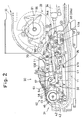
- a portable parts feeder according to an aspect of the present invention is generally indicated at 20 in Fig. 1. All the components of the parts feeder 20 are supported by a frame 22 having a handle 21 which can be held by an operator who carries the same.
- a reel shaft 23 is provided in the frame 22 on the right portion (in Fig. 1) of the parts feeder to rotatably support the tape reel 16.
- On the right side of the reel shaft 23 is provided a reel keeping bar 25 pivoted on the frame 22 through a shaft 24.
- the reel keeping bar 25 is continuously biased by a torsion spring 26 toward the reel shaft 23. Consequently, a roller 27 provided at the front end of the reel keeping bar 25 comes into forceable contact with the outer peripheral surface of the carrier tape 10 regardless of the diameter of the carrier tape 10 wound about the tape reel 16.
- the frame 22 is provided on the left portion (Fig. 1) thereof with immovable tape guide members 28 and 29 secured thereto to guide the carrier tape 10 fed from the tape reel 16.
- the pressing mechanism 30, the pitched feeding mechanism 31, the adhesive tape separating mechanism 32 and the adhesive tape winding mechanism 33 are driven by a single hydraulic cylinder device 34 which is rotatably supported on the frame 22 through a pivot shaft 35 at the rear end of the cylinder device 34.
- the carrier tape 10, the support tape 11, and the adhesive tape 15 are shown by a two-dotted and dashed line, a three-dotted and dashed line, and a four-dotted and dashed line, respectively, in Figs. 1, 2, 4 and 6.
- the pitched feeding mechanism 31 will be described below with reference to Figs. 2 and 3.
- the cylinder device 34 has a piston rod 34a which is pivoted through a pivot shaft 39 to an arm 38a of a crank lever 38 which is in turn pivoted on the frame 22 through a pivot shaft 37.
- the arm 38a is provided on the front end thereof with a pin 40 which is fitted in an elongated hole 41a formed at one end of a driving link 41.
- the other end of the driving link 41 is pivoted through a shaft 44 to a free end of a feed lever 43 pivoted to the frame 22 through a shaft 42.
- a pair of right and left sprocket wheels 45 and a pair of right and left feed gears 46 that are integrally secured to the corresponding sprocket wheels 45 by calking pins 47 are rotatably and coaxially supported by the shaft 42.
- the sprocket wheels 45 are provided on the peripheral surfaces thereof with sprockets 45a which are spaced at an equiangular distance, so that the sprockets 45a can be engaged in the sprocket holes 12 of the carrier tape 10.
- the feed gears 46 have teeth 46a whose angular distance corresponds to the angular distance of the sprockets 45a.
- the feed lever 43 is provided with a feeding pawl 48 and a positioning pawl 49. These pawls 48 and 49 are pivoted by respective shafts 50 and 51 to selectively engage with the teeth 46a of the feed gears 46.
- the feeding pawl 48 is biased by a biasing spring 52 in a direction to selectively engage at the front end thereof with the teeth 46a.
- the positioning pawl 49 is biased by a biasing spring 53 in a direction to be disengaged from the teeth 46a.
- the angular displacement of the feeding pawl 48 and the positioning pawl 49 is restricted by stop pins 54 and 55 provided on the frame 22.
- FIG. 3 there is another positioning pin 58 pivoted on the frame 22 through a shaft 57.
- the front end of the positioning pawl 58 is continuously engaged in one of the teeth 46a of the feed gear 46 by the spring force of a tensile spring 59.
- the feeding pawl 48 causes the feed gears 46 and the sprocket wheels 45 to rotate in the counterclockwise direction "a" through the associated teeth 46a.
- the positioning pawl 58 successively rides over the teeth 46a.
- the largest displacement of the feeding pawl 48 is restricted by the stop pin 54, as mentioned above, and accordingly, a further backward movement of the piston rod 34a causes the pin 40 to move within the elongated hole 41a.
- the position at which the feeding pawl 48 abuts against the stop pin 54 corresponds to a position in which the carrier tape 10 is fed by a unit displacement by the sprockets 45a of the sprocket wheels 45 whose rotation is restricted by the positioning pawl 58.
- the adhesive tape separating mechanism (apparatus) 32 will be discussed below with reference to Figs. 2 and 4.
- the carrier tape 10 fed from the tape reel 16 is moved along and on a tape passage 61 formed on the upper surface of the frame 22 and comes to the adhesive tape separating stage (parts holding stage) 62 where the adhesive tape 15 is separated from the base tape.
- the tape passage 61 in the adhesive tape separating stage 62 is provided with an adhesive tape separating hole 63, as can be seen in Figs. 4 and 6.
- a separating (or peeling) lever 65 is pivoted to the frame 22 through a shaft 64 below the adhesive separating hole 63.
- the separating lever 65 is provided on the rear end thereof with a bifurcated portion 65a in which a roller 67 is fitted.
- the roller 67 is provided on one end of a swing lever 66 which is pivoted on the frame 22 through a pivot shaft 68.
- the swing lever 66 is provided on the other end thereof with a striking surface 66a to which an external force is applied in the direction C (Fig. 4) to rotate the swing lever 66 in the clockwise direction, so that the swing movement of the separating lever 65 (from a position shown by a phantom line to a position shown by a solid line) takes place through the roller 67 and the bifurcated portion 65a. Consequently, the adhesive tape 15 of the carrier tape 10 is separated from the base tape 11.
- the external force to be applied to the striking surface 66a in the direction C is produced by the roller 70 provided on the front end of the other arm 38b of the crank lever 38.
- the separating lever 65 is moved to the separation waiting position shown at the phantom line before the roller 70 of the crank lever 38 strikes the striking surface 66a.
- an engaging lever 72 having an engaging stepped portion 72a is pivoted on the frame 22 through a pivot shaft 71.
- a stop pin 66b is secured to the swing lever 66 and engaged in the engaging stepped portion 72a.
- the engaging lever 72 is continuously biased by a tensile spring 73 in a direction in which the stepped portion 72a is engaged by the stop pin 66b. Therefore, when the stop pin 66b is engaged in the stepped portion 72a, the swing lever 66 and the separating lever 65 are held in the position shown by solid lines in Fig. 4.
- the swing lever 66 is continuously biased toward the separation waiting position by a tensile spring 74.
- the engaging lever 72 is provided on the front end thereof with an auxiliary lever 76 pivoted with respect thereto, which is engaged by a roller 77 rotatably provided on the driving link 41.
- the auxiliary lever 76 is pushed by the roller 77 when the driving link 41 is retracted from the position shown in Fig. 4 (in the right direction) to swing the engaging lever 72.
- the driving link 41 is advanced (in the left direction) while the roller 77 is located on the right side of the auxiliary lever 76, only the auxiliary lever 76 is rotated about the pivot shaft 75 without rotating the engaging lever 72.
- the adhesive tape 15 separated from the base tape by the adhesive tape separating mechanism 32 is advanced towards the adhesive tape winding mechanism 33 through the guide roller 80 coaxial to the pivot shaft 68.
- the following discussion will be directed to the adhesive tape winding mechanism 33 with reference to Figs. 2 and 7.
- the winding lever 84 and the ratchet lever 85 can relatively rotate by an angular displacement defined by the space between the pin 85a and the opening 84a.
- the winding lever 84 and the ratchet lever 85 are biased by a tensile spring 86 to come close to each other, so that the pin 85a abuts against one end of the opening 84a.
- the ratchet lever 85 is provided with a ratchet pawl 87 which pivots about a pivot shaft 88, so that the ratchet lever 85 engages with the ratchet wheel 83.
- the ratchet pawl 87 is continuously biased by a torsion spring 89 in a direction to engage with the ratchet wheel 83.
- the ratchet pawl 87 transmits the rotation of the ratchet lever 85 in the counterclockwise direction to the ratchet wheel 83, and accordingly, the winding reel 82, but does not transmit the rotation of the ratchet lever 85 in the clockwise direction.
- the winding lever 84 is rotatably connected to the arm 38b of the crank lever 38 through a link 90, so that when the piston rod 34a is retracted, the winding lever 84 is rotated in the counterclockwise direction.
- the ratchet lever 85 is rotated together with the winding lever 84 by the force of the tensile spring 86, so that the ratchet pawl 87 rotates the winding reel 82 in the counterclockwise direction through the ratchet wheel 83.
- the adhesive tape 15 is wound about the winding wheel 82.
- the tensile spring 86 is tensed so that the winding lever 84 is movable with respect to the ratchet lever 85 when there is a load above a predetermined value on the rotation of the ratchet lever 85.
- the winding lever 84 is rotated in the clockwise direction, so that the winding lever 84 rotates in the same direction through the engagement of the pin 85a with the opening 84a.
- the ratchet pawl 87 rides over the ratchet wheel 83 and idles with respect to the winding reel 82.
- the pressing mechanism 30 presses the electronic components 14 against the base tape 11 so that the components 14 will not move with respect to the base tape 11 during the separation of the adhesive tape 15 from the base tape 11.
- the pressing mechanism 30 will be discussed below with reference to Figs. 4 through 6.
- the arched guide 94 is provided with grooves 94a from which the sprockets 45a of the sprocket wheels 45 project to prevent base tape 11 of the carrier tape 10 from being disengaged upward from the sprocket wheels 45.
- the guide 94 bears guide marks 94b thereon which are adapted to determine the initial position of the electronic components 14, as shown in Fig. 6.
- the casing 93 is provided on the lower portion thereof with a tape passage 96 in which the carrier tape 10 travels.
- the guide bar 100 slidably supports a slider 101.
- the slider 101 is provided with an electronic component holder 103 that pivots about a shaft 102.
- the electronic component holder 103 has an electronic component keeping spring 104 which is secured thereto by securing screws 105 and which extends above the adhesive tape separating stage 62.
- the shaft 102 is provided on one end thereof with a first radial arm 106 secured thereto, and on the other end with a second radial arm 120.
- a pin 107 extends through the front ends of the radial arms 106 and 120.
- One end 107a of the pin 107 is fitted in a bifurcated portion 110a provided at one end of a driving lever 110 which is pivoted on the frame 22 through a shaft 108.
- a movement transmitting link 112 is rotatably connected at one end thereof to the other end of the driving lever 110 through a shaft 111.
- the movement transmitting link 112 is provided on the other end with an elongated hole 112a (Fig. 2) in which a pin 113 provided on the crank lever 38 is fitted.
- a spring 115 (Fig. 7) is provided between the pin 113 and a spring connecting pin 114 provided on the movement transmitting link 112.
- the electronic component holder 103 which is swingable about the shaft 102 with respect to the slider 101 is continuously biased by a compression spring 116, provided between the lower surface of the electronic component holder 103 and the upper surface of the slider 101, in the clockwise direction shown in Fig. 5.
- the angular displacement of the electronic component holder 103 is restricted by a stop pin 118 provided on the slider 101.
- the second radial arm 120 is provided with a radially extending lever portion 120a integral therewith, at an axial position different from the first radial arm 106.
- the lever portion 120a is provided on the front end thereof with an association pin 121 which is engaged in an association groove 122 formed in the electronic component holder 103.
- a tensile spring (return spring) 123 is provided between the other end 107b of the pin 107 and the electronic component holder 103 to rotate and return the pin 107 about the shaft 102 in the clockwise direction.
- Numeral 140 designates a guide which holds the slider 101 between the guide 140 and the casing 93 to restrict the rotation of the slider 101.
- the electronic component keeping spring 104 secured to the electronic component holder 103 is translated along the adhesive tape separating stage 62 until the slider 101 which moves along the guide bar 100 comes into contact with the stop surface 126.
- the rotation of the electronic component holder 103 about the shaft 102 in the counterclockwise direction takes place after the slider 101 abuts against the stop surface 126, the electronic component keeping spring 104 moves toward the adhesive tape separating stage 62, so that the electronic component 14 on the base tape 11 can be held by the front end of the electronic component keeping spring 104.
- the above-mentioned movement of the electronic component keeping spring 104 is indicated at arrows "x" and "y” in Fig. 4, respectively.
- the electronic components 14 can be prevented from being displaced on the base tape 11.
- the sequence of the operations is controlled such that the keeping operation of the electronic components 14 by the electronic component keeping spring 104 is effected immediately before the adhesive tape 15 is separated from the base tape by the adhesive tape separating mechanism 32. Accordingly, it is possible to commence the separation of the adhesive tape from the base tape even before the associated electronic component 14 is suctioned by the chip mounting device (not shown), i.e., without awaiting the completion of the suction operation of the electronic components 14 by the chip mounting device.
- the suction operation of the electronic components 14 by the chip mounting device can be optionally carried out at an appropriate time after the electronic components 14 are firmly held by the electronic component keeping spring 104.
- a shaft of the roller 70 is eccentric with regard to the center of the roller, so that the time at which the roller 70 strikes the striking surface 66a of the swing lever 66 is adjusted by changing the direction of the roller 70 about the axis and securing the roller to the arm 38b.
- the vacuum suction holes 124 which are connected to the vacuum suction pipe 125 suction the base tape 11 at a time different from the time at which the pitched feeding mechanism 31 intermittently feeds the carrier tape 10. Consequently, no accidental movement of the base tape 11 occurs when the electronic components 14 are held by the pressing mechanism (holding mechanism) 30 or the adhesive tape 15 is separated from the adhesive tape separating mechanism 32, thus resulting in not only a stable keeping operation of the electronic components 14, but also a stable separation of the adhesive tape 15.
- Numeral 130 in Fig. 1 designates a cutter for the base tape 11.
- the cutter 130 has a circular blade 131 which is rotatably supported by the frame 22 through a shaft 132.
- the frame 22 is provided with a groove 133 in which the circular blade 131 opens. Consequently, the base tape 11 which is inserted in the groove 133 can be cut by the circular blade 131.
- the parts disposed on the base tape can be firmly held on the base tape before the adhesive tape is separated from the base tape, and accordingly, the separation of the adhesive tape from the base tape can be carried out before the parts are suctioned by the chip mounting device, i.e., without awaiting the completion of the suction operation of the parts by the chip mounting device. Consequently, the feeding interval (time) of the parts can be shortened.
Abstract
Description
- The present invention relates to a parts feeder which conveys and feeds parts held by a carrier tape.
- In a known parts feeder, parts to be conveyed are held on a carrier tape having a support tape (base tape) which is provided with holes spaced at an equidistance and an adhesive tape adhered to a lower surface of the support tape. The adhesive tape is adhered to the bottoms of the parts disposed on the holes to immovably hold the parts. Namely, the adhesive tape is bent into the holes of the support tape so that the adhesive tape can be adhered to the bottoms of the parts exposed to the through holes. In such a known parts feeder, when the adhesive tape is separated from the support tape, the connection between the parts and the adhesive tape is broken, so that the parts are merely disposed on the support tape without an adhesion thereto, thus resulting in a displacement of the parts from the support tape. To prevent this, the operation sequence was formulated such that the separation of the adhesive tape from the support tape takes place after a suction force is applied to the parts by a suction nozzle of a part mounting device. In this sequence, however, since no separation of the adhesive tape from the support tape can be effected until the parts are held by the suction device, the time intervals for feeding the parts are increased, resulting in an increased time for the feeding operation.
- The primary object of the present invention is to provide a parts feeder using a carrier tape, wherein the time intervals of the parts feeding operation can be shortened
- The inventors of the present application have found that if the parts to be fed are pressed against the support tape of the carrier tape before the adhesive tape is separated or stripped from the support tape, the separation of the adhesive tape from the support tape can be carried out without waiting for the completion of the suction operation of the parts by the suction nozzle.
- Namely, to achieve the object mentioned above, according to the present invention, there is provided a parts feeder for feeding parts that are disposed on a carrier tape consisting of a base tape and an adhesive tape, wherein the parts are disposed above holes which are formed at equal intervals on the base tape, and wherein the parts are held by an adhesive tape adhered to a lower surface of the base tape. The parts feeder includes a pitched feeding mechanism for intermittently feeding the carrier tape at a predetermined pitch, a separating mechanism for separating the adhesive tape from the base tape in synchronization with the feeding of the carrier tape at an adhesive tape separating stage, and a pressing mechanism for pressing the parts disposed on the base tape against the base tape prior to the separation of the adhesive tape from the base tape at the adhesive tape separating stage.
- Preferably, the parts feeder includes a suction mechanism for applying a suction force to the surface of the base tape opposite the surface on which the parts are disposed in synchronization with the feeding of the carrier tape at the adhesive tape separating stage.
- The separating mechanism can include, for example, a tape passage on which the carrier tape is fed, an adhesive tape separating hole provided on the tape passage through which the adhesive tape is fed when separated from the carrier tape and, a separating lever positioned below the separating hole, wherein the separating lever is swung in contact with the adhesive tape to separate the adhesive tape from the base tape.
- The pressing mechanism can include, for example, a slider which is movable above the tape passage and in a direction parallel to the tape passage, a component holder which is pivoted with respect to the slider and capable of pressing the parts against the base tape when pivoted, wherein the component holder has a component holding leaf spring which contacts and presses the parts against the base tape, a moving device for moving the slider towards the separating hole, and a swinging mechanism for swinging the component holder towards the parts after the slider is moved a predetermined distance by the slider moving device so that the component holder presses the parts against the base tape.
- It is possible that the parts feeder include a stopper which restricts movement of the slider in a direction parallel to the tape passage after the slider has moved through the predetermined distance, wherein the component holder is swung by the force applied by the slider moving mechanism when movement of the slider is restricted, and a spring which biases the component holder away from the carriage tape.
- The parts feeder preferably includes a single hydraulic device which actuates the pitched feeding mechanism, the separating mechanism, and the pressing mechanism. An adhesive tape winding mechanism for winding the adhesive tape after the tape is separated from the base tape may also be provided.
- The pitched feeding mechanism preferably includes a pair of sprocket wheels which engage with a series of sprocket holes on opposite edges of the base tape, and a mechanism for rotating the pair of sprocket wheels in a manner such that the sprocket wheels rotate intermittently so that the base tape is moved intermittently.
- According to another aspect of the present invention, there is provided a parts feeder for feeding parts that are disposed on a carrier tape consisting of a base tape and an adhesive tape, wherein the parts are disposed above holes which are formed at equal intervals on the base tape and held by an adhesive tape adhered to a lower surface of the base tape. The parts feeder includes a pitched feeding mechanism for intermittently feeding the carrier tape at a predetermined pitch, a separating mechanism for separating the adhesive tape from the base tape in synchronization with the feeding of the carrier tape at an adhesive tape separating stage, and a suction mechanism for applying a suction force to the surface of the base tape opposite the surface on which the parts are disposed in synchronization with the feeding of the carrier tape at the adhesive tape separating stage.
- According to this aspect of the invention, it is preferable that the parts feeder include a pressing mechanism for pressing the parts disposed on the base tape against the base tape prior to the separation of the adhesive tape from the base tape at the adhesive tape separating stage.
- The invention will be described below in detail with reference to the accompanying drawings, in which;
- Fig. 1 is a front elevational view of a parts feeder according to an aspect of the present invention;
- Fig. 2 is an enlarged front elevational view of a main part of a parts feeder according to the present invention;
- Fig. 3 is an enlarged front elevational view of a pitched feeding mechanism of a parts feeder according to the present invention;
- Fig. 4 is an enlarged front elevational view of a separation stage of an adhesive tape in a parts feeder according to the present invention;
- Fig. 5 is an enlarged front elevational view of a pressing mechanism of parts in a parts feeder according to the present invention;
- Fig. 6 is a plan view of Fig. 5;
- Fig. 7 is an enlarged front elevational view of an adhesive tape winding mechanism in a parts feeder according to the present invention;
- Fig. 8 is a plan view of a carrier tape used in a parts feeder according to the present invention, by way of example; and,
- Fig. 9 is a sectional view taken along the line A-A in Fig. 8.
- Figs. 8 and 9 show a
carrier tape 10 for the parts to be fed, used in a parts feeder according to the present invention. Thecarrier tape 10 is comprised of a support tape (i.e., base tape) 11 which is provided on opposite side edges thereof with a number of sprocket holes (perforations) 12 which are spaced at an equidistance p (e.g., p=4 mm). Thesupport tape 11 is also provided with a number of through holes oropenings 13 which are spaced at an equidistance np (n = a natural number). Electronic components (parts to be fed) 14 are disposed on the throughholes 13. - The
carrier tape 10 has anadhesive tape 15 which is adhered to the lower surface of thesupport tape 11. Theadhesive tape 15 is bent or deformed into the throughholes 13, so that theadhesive tape 15 is adhered to the bottom surface of theelectronic components 14 to immovably hold the same on thesupport tape 11. The value of "n" is predetermined depending on the size of theelectronic components 14. Thecarrier tape 10 is wound about a tape reel 16 (Fig. 1) and is unwound therefrom to perform the feeding operation. - A portable parts feeder according to an aspect of the present invention is generally indicated at 20 in Fig. 1. All the components of the
parts feeder 20 are supported by aframe 22 having ahandle 21 which can be held by an operator who carries the same. Areel shaft 23 is provided in theframe 22 on the right portion (in Fig. 1) of the parts feeder to rotatably support thetape reel 16. On the right side of thereel shaft 23 is provided areel keeping bar 25 pivoted on theframe 22 through ashaft 24. Thereel keeping bar 25 is continuously biased by atorsion spring 26 toward thereel shaft 23. Consequently, aroller 27 provided at the front end of thereel keeping bar 25 comes into forceable contact with the outer peripheral surface of thecarrier tape 10 regardless of the diameter of thecarrier tape 10 wound about thetape reel 16. - The
frame 22 is provided on the left portion (Fig. 1) thereof with immovabletape guide members carrier tape 10 fed from thetape reel 16. There are apressing mechanism 30 of the parts, apitched feeding mechanism 31 of the parts, and an adhesivetape separating mechanism 32, in front of thetape guide member 29. There is an adhesivetape winding mechanism 33 provided below theguide member 29. Thepressing mechanism 30, thepitched feeding mechanism 31, the adhesivetape separating mechanism 32 and the adhesivetape winding mechanism 33 are driven by a singlehydraulic cylinder device 34 which is rotatably supported on theframe 22 through apivot shaft 35 at the rear end of thecylinder device 34. Thecarrier tape 10, thesupport tape 11, and theadhesive tape 15 are shown by a two-dotted and dashed line, a three-dotted and dashed line, and a four-dotted and dashed line, respectively, in Figs. 1, 2, 4 and 6. - The pitched
feeding mechanism 31 will be described below with reference to Figs. 2 and 3. - The
cylinder device 34 has apiston rod 34a which is pivoted through apivot shaft 39 to anarm 38a of acrank lever 38 which is in turn pivoted on theframe 22 through apivot shaft 37. Thearm 38a is provided on the front end thereof with apin 40 which is fitted in anelongated hole 41a formed at one end of adriving link 41. The other end of thedriving link 41 is pivoted through ashaft 44 to a free end of afeed lever 43 pivoted to theframe 22 through ashaft 42. There is atensile spring 36 between thepin 40 and thedriving link 41, so that thepin 40 is normally brought into contact with one end of theelongated hole 41a. - A pair of right and
left sprocket wheels 45 and a pair of right andleft feed gears 46 that are integrally secured to thecorresponding sprocket wheels 45 by calkingpins 47 are rotatably and coaxially supported by theshaft 42. Thesprocket wheels 45 are provided on the peripheral surfaces thereof withsprockets 45a which are spaced at an equiangular distance, so that thesprockets 45a can be engaged in thesprocket holes 12 of thecarrier tape 10. Thefeed gears 46 haveteeth 46a whose angular distance corresponds to the angular distance of thesprockets 45a. - The
feed lever 43 is provided with a feedingpawl 48 and apositioning pawl 49. Thesepawls respective shafts teeth 46a of the feed gears 46. The feedingpawl 48 is biased by a biasingspring 52 in a direction to selectively engage at the front end thereof with theteeth 46a. Thepositioning pawl 49 is biased by a biasingspring 53 in a direction to be disengaged from theteeth 46a. The angular displacement of the feedingpawl 48 and thepositioning pawl 49 is restricted by stop pins 54 and 55 provided on theframe 22. - As can be seen in Fig. 3, there is another
positioning pin 58 pivoted on theframe 22 through ashaft 57. The front end of thepositioning pawl 58 is continuously engaged in one of theteeth 46a of thefeed gear 46 by the spring force of atensile spring 59. - In the pitched
feeding mechanism 31 as constructed above, when thepiston rod 34a of thecylinder device 34 is retracted or moved from the position shown in Fig. 2 (i.e., in the right direction in Fig. 2), thecrank lever 38 is rotated about theshaft 37 in the counterclockwise direction. Consequently, the drivinglink 41 is moved backward by the spring force of thetensile spring 36 through thepin 40 and thespring engaging pin 41b, so that the feedingpawl 48 is moved in the same direction while engaging with one of theteeth 46a of the feed gears 46. Thepositioning pawl 49 is disengaged from theteeth 46a by the spring force of the biasingspring 53. Consequently, the feedingpawl 48 causes the feed gears 46 and thesprocket wheels 45 to rotate in the counterclockwise direction "a" through the associatedteeth 46a. When the rotation of the feed gears 46 in the counterclockwise direction "a" occurs, thepositioning pawl 58 successively rides over theteeth 46a. The largest displacement of the feedingpawl 48 is restricted by thestop pin 54, as mentioned above, and accordingly, a further backward movement of thepiston rod 34a causes thepin 40 to move within theelongated hole 41a. The position at which the feedingpawl 48 abuts against thestop pin 54 corresponds to a position in which thecarrier tape 10 is fed by a unit displacement by thesprockets 45a of thesprocket wheels 45 whose rotation is restricted by thepositioning pawl 58. - Thereafter, when the
piston rod 34a is moved forward (i.e., in the left direction in Fig. 2), the drivinglink 41 is returned to the position shown in Fig. 3, so that thepositioning pawl 49 comes into contact with thestop pin 55 and is rotated thereby. Consequently, thepositioning pawl 49 engages with one of theteeth 46a of the feed gears 46. During the return of the drivinglink 41 to the initial position, the rotation of the feed gears 46 (in the clockwise direction "b") is restricted by thepositioning pawl 58, and the feedingpawl 48 is returned to the initial position while riding over theteeth 46a. When the drivinglink 41 is returned, thepositioning pawl 49 comes into engagement with one of theteeth 46a of the feed gears 46 to retain the drivinglink 41 and the feedingpawl 48 at a predetermined position. - The adhesive tape separating mechanism (apparatus) 32 will be discussed below with reference to Figs. 2 and 4.
- The
carrier tape 10 fed from thetape reel 16 is moved along and on atape passage 61 formed on the upper surface of theframe 22 and comes to the adhesive tape separating stage (parts holding stage) 62 where theadhesive tape 15 is separated from the base tape. Thetape passage 61 in the adhesivetape separating stage 62 is provided with an adhesivetape separating hole 63, as can be seen in Figs. 4 and 6. A separating (or peeling)lever 65 is pivoted to theframe 22 through ashaft 64 below theadhesive separating hole 63. The separatinglever 65 is provided on the rear end thereof with abifurcated portion 65a in which aroller 67 is fitted. Theroller 67 is provided on one end of aswing lever 66 which is pivoted on theframe 22 through apivot shaft 68. Theswing lever 66 is provided on the other end thereof with astriking surface 66a to which an external force is applied in the direction C (Fig. 4) to rotate theswing lever 66 in the clockwise direction, so that the swing movement of the separating lever 65 (from a position shown by a phantom line to a position shown by a solid line) takes place through theroller 67 and thebifurcated portion 65a. Consequently, theadhesive tape 15 of thecarrier tape 10 is separated from thebase tape 11. The external force to be applied to thestriking surface 66a in the direction C is produced by theroller 70 provided on the front end of theother arm 38b of thecrank lever 38. - The separating
lever 65 is moved to the separation waiting position shown at the phantom line before theroller 70 of thecrank lever 38 strikes thestriking surface 66a. To this end, an engaginglever 72 having an engaging steppedportion 72a is pivoted on theframe 22 through apivot shaft 71. Astop pin 66b is secured to theswing lever 66 and engaged in the engaging steppedportion 72a. The engaginglever 72 is continuously biased by atensile spring 73 in a direction in which the steppedportion 72a is engaged by thestop pin 66b. Therefore, when thestop pin 66b is engaged in the steppedportion 72a, theswing lever 66 and the separatinglever 65 are held in the position shown by solid lines in Fig. 4. Moreover, theswing lever 66 is continuously biased toward the separation waiting position by atensile spring 74. - The engaging
lever 72 is provided on the front end thereof with anauxiliary lever 76 pivoted with respect thereto, which is engaged by aroller 77 rotatably provided on the drivinglink 41. Theauxiliary lever 76 is pushed by theroller 77 when the drivinglink 41 is retracted from the position shown in Fig. 4 (in the right direction) to swing the engaginglever 72. On the other hand, when the drivinglink 41 is advanced (in the left direction) while theroller 77 is located on the right side of theauxiliary lever 76, only theauxiliary lever 76 is rotated about thepivot shaft 75 without rotating the engaginglever 72. - In the adhesive
tape separating mechanism 32 as constructed above, it is now assumed that the steppedportion 72a is engaged by thestop pin 66 of theswing lever 66. In this state, if the drivinglink 41 is moved rearward by thepiston rod 34a, theroller 77 causes the engaginglever 72 to rotate in the counterclockwise direction about thepivot shaft 71 through theauxiliary lever 76. As a result, the engaging steppedportion 72a is disengaged from thestop pin 66b, so that theswing lever 66 is released from the engaginglever 72. Consequently, theswing lever 66 is moved by thetensile spring 74 from the position shown by the solid line to the position shown by a two-dotted and dashed line. The latter position corresponds to the separation waiting position. - When a further rearward movement of the
piston rod 34a occurs, thecrank lever 38 is rotated in the counterclockwise direction, and theroller 70 of thearm 38b thereof strikes thestriking surface 66a. As a result, theswing lever 66 and the separatinglever 65 are moved to the position shown by the solid line from the separation waiting position (two-dotted and dashed line position) to separate theadhesive tape 15 from thebase tape 11 of thecarrier tape 10. The separation of the adhesive tape is synchronous with the pitched feeding of thecarrier tape 10, so that the separation takes place simultaneously with the feed of the carrier tape. - When the
swing lever 66 is moved to the position shown by the solid line from the separation waiting position (two-dotted and dashed line position), the steppedportion 72a of the engaginglever 72, which is biased by thetensile spring 73 to rotate in the clockwise direction, is engaged by thestop pin 66b of theswing lever 66 to again hold theswing lever 66 in the position shown at the solid line. Thereafter, when thepiston rod 34a is returned (advanced) and the drivinglink 41 is moved forward, theroller 77 of the drivinglink 41 pushes theauxiliary lever 76, so that the latter rotates about thepivot shaft 75 without swinging the engaginglever 72 and is then returned to the initial position by the spring force of thespring 78. - The
adhesive tape 15 separated from the base tape by the adhesivetape separating mechanism 32 is advanced towards the adhesivetape winding mechanism 33 through theguide roller 80 coaxial to thepivot shaft 68. The following discussion will be directed to the adhesivetape winding mechanism 33 with reference to Figs. 2 and 7. - An adhesive
tape winding shaft 81 is provided in theframe 22 to support a windingreel 82 through a one-way clutch so as to rotate in only one direction. Aratchet wheel 83 is secured to the windingreel 82. The adhesivetape winding shaft 81 coaxially supports a windinglever 84 and aratchet lever 85. The windinglever 84 is provided with anopening 84a in which apin 85a secured to theratchet lever 85 is fitted. The windinglever 84 and theratchet lever 85 are relatively rotatable within an angular range defined by the circumferential width of theopening 84a. Namely, the windinglever 84 and theratchet lever 85 can relatively rotate by an angular displacement defined by the space between thepin 85a and theopening 84a. The windinglever 84 and theratchet lever 85 are biased by atensile spring 86 to come close to each other, so that thepin 85a abuts against one end of theopening 84a. - The
ratchet lever 85 is provided with aratchet pawl 87 which pivots about apivot shaft 88, so that theratchet lever 85 engages with theratchet wheel 83. Theratchet pawl 87 is continuously biased by atorsion spring 89 in a direction to engage with theratchet wheel 83. Theratchet pawl 87 transmits the rotation of theratchet lever 85 in the counterclockwise direction to theratchet wheel 83, and accordingly, the windingreel 82, but does not transmit the rotation of theratchet lever 85 in the clockwise direction. - The winding
lever 84 is rotatably connected to thearm 38b of thecrank lever 38 through alink 90, so that when thepiston rod 34a is retracted, the windinglever 84 is rotated in the counterclockwise direction. When the rotation of the windinglever 84 in the counterclockwise direction takes place, theratchet lever 85 is rotated together with the windinglever 84 by the force of thetensile spring 86, so that theratchet pawl 87 rotates the windingreel 82 in the counterclockwise direction through theratchet wheel 83. Thus, theadhesive tape 15 is wound about the windingwheel 82. Thetensile spring 86 is tensed so that the windinglever 84 is movable with respect to theratchet lever 85 when there is a load above a predetermined value on the rotation of theratchet lever 85. When thepiston rod 34a is moved forward, the windinglever 84 is rotated in the clockwise direction, so that the windinglever 84 rotates in the same direction through the engagement of thepin 85a with theopening 84a. During this rotation, theratchet pawl 87 rides over theratchet wheel 83 and idles with respect to the windingreel 82. - The
pressing mechanism 30 presses theelectronic components 14 against thebase tape 11 so that thecomponents 14 will not move with respect to thebase tape 11 during the separation of theadhesive tape 15 from thebase tape 11. Thepressing mechanism 30 will be discussed below with reference to Figs. 4 through 6. - A pair of right and left mounting
plates 92 are secured to theframe 22 throughscrews 91 in the vicinity of thetape passage 61. Between the mountingplates 92 is secured acasing 93 to which aguide bar 100 extending in the direction of the travel of thecarrier tape 10 is secured. Anarched guide 94 is secured to the front end of thecasing 93 by securingscrews 95 and lie along and above the right and leftsprocket wheels 45 of the pitchedfeeding mechanism 31 to prevent the upward movement (floating or flapping) of the carrier tape during the movement along and on the tape passage. Thearched guide 94 is provided withgrooves 94a from which thesprockets 45a of thesprocket wheels 45 project to preventbase tape 11 of thecarrier tape 10 from being disengaged upward from thesprocket wheels 45. Theguide 94 bears guidemarks 94b thereon which are adapted to determine the initial position of theelectronic components 14, as shown in Fig. 6. Thecasing 93 is provided on the lower portion thereof with atape passage 96 in which thecarrier tape 10 travels. - The
guide bar 100 slidably supports aslider 101. Theslider 101 is provided with anelectronic component holder 103 that pivots about ashaft 102. Theelectronic component holder 103 has an electroniccomponent keeping spring 104 which is secured thereto by securingscrews 105 and which extends above the adhesivetape separating stage 62. Theshaft 102 is provided on one end thereof with a firstradial arm 106 secured thereto, and on the other end with a secondradial arm 120. Apin 107 extends through the front ends of theradial arms end 107a of thepin 107 is fitted in a bifurcated portion 110a provided at one end of a drivinglever 110 which is pivoted on theframe 22 through ashaft 108. Amovement transmitting link 112 is rotatably connected at one end thereof to the other end of the drivinglever 110 through ashaft 111. Themovement transmitting link 112 is provided on the other end with anelongated hole 112a (Fig. 2) in which apin 113 provided on thecrank lever 38 is fitted. A spring 115 (Fig. 7) is provided between thepin 113 and aspring connecting pin 114 provided on themovement transmitting link 112. - The
electronic component holder 103 which is swingable about theshaft 102 with respect to theslider 101 is continuously biased by acompression spring 116, provided between the lower surface of theelectronic component holder 103 and the upper surface of theslider 101, in the clockwise direction shown in Fig. 5. The angular displacement of theelectronic component holder 103 is restricted by astop pin 118 provided on theslider 101. The secondradial arm 120 is provided with a radially extendinglever portion 120a integral therewith, at an axial position different from the firstradial arm 106. Thelever portion 120a is provided on the front end thereof with anassociation pin 121 which is engaged in anassociation groove 122 formed in theelectronic component holder 103. A tensile spring (return spring) 123 is provided between theother end 107b of thepin 107 and theelectronic component holder 103 to rotate and return thepin 107 about theshaft 102 in the clockwise direction.Numeral 140 designates a guide which holds theslider 101 between theguide 140 and thecasing 93 to restrict the rotation of theslider 101. - The adhesive
tape separating stage 62 is provided with a plurality of vacuum suction holes 124 (Fig. 6) surrounding the adhesivetape separating opening 63 to suction the base tape (support tape) 11 from which theadhesive tape 15 has been separated. The vacuum suction holes 124 are connected to avacuum suction pipe 125 to supply the vacuum suction holes 124 with vacuum (negative pressure), as shown in Fig. 5. - In the
pressing mechanism 30 as constructed above, when thecrank lever 38 is rotated in the counterclockwise direction by the rearward movement of thepiston rod 34a, themovement transmitting link 112 is moved rearward through thepin 113, so that the drivinglever 110 is rotated in the counterclockwise direction about theshaft 108. As a result, theslider 101 which supports theelectronic component holder 103 moves forward along theguide bar 100. When theslider 101 comes into contact with thestop surface 126 of thecasing 93, no further movement of theslider 101 occurs, but the drivinglever 110 continues rotating. Consequently, the rotation of theradial arms shaft 102 in the counterclockwise direction takes place, so that theassociation pin 121 of thelever portion 120a pushes theelectronic component holder 103 through the end surface of theassociation groove 122. Namely, theelectronic component holder 103 to which the rotational force is applied is rotated about theshaft 102 in the counterclockwise direction. - Consequently, the electronic
component keeping spring 104 secured to theelectronic component holder 103 is translated along the adhesivetape separating stage 62 until theslider 101 which moves along theguide bar 100 comes into contact with thestop surface 126. The rotation of theelectronic component holder 103 about theshaft 102 in the counterclockwise direction takes place after theslider 101 abuts against thestop surface 126, the electroniccomponent keeping spring 104 moves toward the adhesivetape separating stage 62, so that theelectronic component 14 on thebase tape 11 can be held by the front end of the electroniccomponent keeping spring 104. The above-mentioned movement of the electroniccomponent keeping spring 104 is indicated at arrows "x" and "y" in Fig. 4, respectively. Thus, theelectronic components 14 can be prevented from being displaced on thebase tape 11. In the present invention, the sequence of the operations is controlled such that the keeping operation of theelectronic components 14 by the electroniccomponent keeping spring 104 is effected immediately before theadhesive tape 15 is separated from the base tape by the adhesivetape separating mechanism 32. Accordingly, it is possible to commence the separation of the adhesive tape from the base tape even before the associatedelectronic component 14 is suctioned by the chip mounting device (not shown), i.e., without awaiting the completion of the suction operation of theelectronic components 14 by the chip mounting device. The suction operation of theelectronic components 14 by the chip mounting device can be optionally carried out at an appropriate time after theelectronic components 14 are firmly held by the electroniccomponent keeping spring 104. - It is preferred that a shaft of the
roller 70 is eccentric with regard to the center of the roller, so that the time at which theroller 70 strikes thestriking surface 66a of theswing lever 66 is adjusted by changing the direction of theroller 70 about the axis and securing the roller to thearm 38b. - The vacuum suction holes 124 which are connected to the
vacuum suction pipe 125 suction thebase tape 11 at a time different from the time at which the pitchedfeeding mechanism 31 intermittently feeds thecarrier tape 10. Consequently, no accidental movement of thebase tape 11 occurs when theelectronic components 14 are held by the pressing mechanism (holding mechanism) 30 or theadhesive tape 15 is separated from the adhesivetape separating mechanism 32, thus resulting in not only a stable keeping operation of theelectronic components 14, but also a stable separation of theadhesive tape 15. -
Numeral 130 in Fig. 1 designates a cutter for thebase tape 11. Thecutter 130 has acircular blade 131 which is rotatably supported by theframe 22 through ashaft 132. Theframe 22 is provided with agroove 133 in which thecircular blade 131 opens. Consequently, thebase tape 11 which is inserted in thegroove 133 can be cut by thecircular blade 131. - As can be seen from the above discussion, according to the present invention, the parts disposed on the base tape can be firmly held on the base tape before the adhesive tape is separated from the base tape, and accordingly, the separation of the adhesive tape from the base tape can be carried out before the parts are suctioned by the chip mounting device, i.e., without awaiting the completion of the suction operation of the parts by the chip mounting device. Consequently, the feeding interval (time) of the parts can be shortened.
Claims (13)
- A parts feeder (20) for feeding parts (14) that are disposed on a carrier tape (10) consisting of a base tape (11) and an adhesive tape (15), wherein the parts (14) are disposed above holes (13) which are formed at equal intervals on the base tape (11), and wherein the parts (14) are held by the adhesive tape (15) adhered to a lower surface of the base tape (11), comprising:
a pitched feeding means (31) for intermittently feeding the carrier tape (10) at a predetermined pitch;
means (32) for separating the adhesive tape (15) from the base tape (11) in synchronization with the feeding of the carrier tape (10) at an adhesive tape separating stage (62); and,
means (30) for pressing the parts (14) disposed on the base tape (11) against the base tape prior to the separation of the adhesive tape (15) from the base tape (11) at the adhesive tape separating stage (62). - The parts feeder of claim 1, further comprising:
a suction means (124, 125) for applying a suction force to the surface of the base tape (11) opposite the surface on which the parts (14) are disposed in synchronization with the feeding of the carrier tape (10) at the adhesive tape separating stage (62). - The parts feeder of claim 1 or 2, wherein said separating means (32) comprises:
a tape passage (61) on which said carrier tape (10) is fed; an adhesive tape separating hole (63), provided on said tape passage (61), through which said adhesive tape (15) is fed when separated from said carrier tape (10); and,
a separating lever (65) positioned below said separating hole (63), said separating lever (65) swung in contact with said adhesive tape (15) to separate said adhesive tape (15) from said base tape (11). - The parts feeder of claim 3, wherein said pressing means (30) comprises:
a slider (101) which is movable above said tape passage (61) and in a direction parallel to the tape passage (61);
a component holder (103) which is pivoted with respect to said slider (101) and capable of pressing said parts (14) against said base tape (11) when pivoted;
means for moving said slider (101) towards said separating hole (63); and,
means for swinging said component holder (103) towards said parts (14) after said slider (101) is moved a predetermined distance by said slider moving means so that the component holder (103) presses said parts (14) against said base tape (11). - The parts feeder of claim 4, wherein said component holder (103) has a component holding leaf spring (104) which contacts and presses said parts (14) against said base tape (11).
- The parts feeder of claim 4 or 5, further comprising:
a stopper (126) which restricts movement of said slider (101) in a direction parallel to the tape passage (61) after said slider (101) has moved through said predetermined distance, wherein said component holder (103) is swung by the force applied by said slider moving means when movement of said slider (101) is restricted by said stopper (126). - The parts feeder of one of claims 4 to 6, further comprising:
a spring (116) which biases said component holder (103) away from said carriage tape (10). - The parts feeder of one of claims 1 to 7, further comprising:
a single hydraulic device (34) which actuates said pitched feeding means (31), said separating means (32), and said pressing means (30). - The parts feeder of one of claims 1 to 8, further comprising:
an adhesive tape winding means (33) which winds said adhesive tape (15) after the tape is separated from said base tape (11). - The parts feeder of claim 9, further comprising:
a single hydraulic device (34) which actuates said pitched feeding means (31), said separating means (32), said pressing means (30), and said adhesive tape winding means (33). - The parts feeder of one of claims 1 to 10, wherein said base tape (11) has a series of sprocket holes (12) on opposite edges thereof.
- The parts feeder of claim 11, wherein said pitched feeding means (31) comprises:
a pair of sprocket wheels (45) which engages with said series of sprocket holes (12); and,
means for rotating said pair of sprocket wheels (45) in a manner such that the sprocket wheels (45) rotate intermittently so that the base tape (11) is moved intermittently. - A parts feeder (20) for feeding parts (14) that are disposed on a carrier tape (10) consisting of a base tape (11) and an adhesive tape (15), wherein the parts (14) are disposed above holes (13) which are formed at equal intervals on the base tape (11) and held by an adhesive tape (15) adhered to a lower surface of the base tape (11), comprising:
a pitched feeding means (31) for intermittently feeding the carrier tape (10) at a predetermined pitch;
means (32) for separating the adhesive tape (15) from the base tape (11) in synchronization with the feeding of the carrier tape (10) at an adhesive tape separating stage (62); and,
a suction means (124, 125) for applying a suction force to the surface of the base tape (11) opposite the surface on which the parts (14) are disposed in synchronization with the feeding of the carrier tape (10) at the adhesive tape separating stage (62).
Applications Claiming Priority (2)
| Application Number | Priority Date | Filing Date | Title |
|---|---|---|---|
| JP147205/93 | 1993-06-18 | ||
| JP5147205A JPH077292A (en) | 1993-06-18 | 1993-06-18 | Component supplying apparatus |
Publications (1)
| Publication Number | Publication Date |
|---|---|
| EP0630177A1 true EP0630177A1 (en) | 1994-12-21 |
Family
ID=15424945
Family Applications (1)
| Application Number | Title | Priority Date | Filing Date |
|---|---|---|---|
| EP94109300A Withdrawn EP0630177A1 (en) | 1993-06-18 | 1994-06-16 | Parts feeder |
Country Status (5)
| Country | Link |
|---|---|
| US (1) | US5492593A (en) |
| EP (1) | EP0630177A1 (en) |
| JP (1) | JPH077292A (en) |
| KR (1) | KR950002554A (en) |
| TW (1) | TW241239B (en) |
Cited By (1)
| Publication number | Priority date | Publication date | Assignee | Title |
|---|---|---|---|---|
| EP0967852A2 (en) * | 1998-06-24 | 1999-12-29 | FUJI MACHINE Mfg. Co., Ltd. | Electric-component tape feeding apparatus and electric-component supplying method |
Families Citing this family (8)
| Publication number | Priority date | Publication date | Assignee | Title |
|---|---|---|---|---|
| JP3404431B2 (en) * | 1994-07-04 | 2003-05-06 | 富士機械製造株式会社 | Electronic component supply cartridge and electronic component supply / extraction device |
| JP3397900B2 (en) * | 1994-08-12 | 2003-04-21 | 富士機械製造株式会社 | Electronic component supply device |
| DE69737545T2 (en) * | 1996-05-13 | 2007-12-13 | Matsushita Electric Industrial Co., Ltd., Kadoma | DEVICE FOR FEEDING ELECTRONIC COMPONENTS |
| SE517579C2 (en) * | 1999-03-10 | 2002-06-25 | Foerpackningsinnovation Norden | Feeder unit for feeding a packaging medium |
| JP5408146B2 (en) * | 2011-01-25 | 2014-02-05 | パナソニック株式会社 | Tape feeder and tape loading method in tape feeder |
| WO2016088224A1 (en) * | 2014-12-03 | 2016-06-09 | 富士機械製造株式会社 | Tape feeder |
| TWI567011B (en) * | 2016-06-15 | 2017-01-21 | All Ring Tech Co Ltd | Method and device for conveying the components of the bonding process |
| CN116902285B (en) * | 2023-09-12 | 2023-12-26 | 山西星心半导体科技有限公司 | Braiding machine for producing LED lamp beads |
Citations (3)
| Publication number | Priority date | Publication date | Assignee | Title |
|---|---|---|---|---|
| US4915770A (en) * | 1987-05-09 | 1990-04-10 | Hitachi, Ltd. | Electronic chip supplying apparatus and method |
| EP0423599A1 (en) * | 1989-10-17 | 1991-04-24 | Sanyo Electric Co., Ltd. | Cover-tape peeling apparatus for a tape feeder |
| EP0523714A1 (en) * | 1991-07-19 | 1993-01-20 | Matsushita Electric Industrial Co., Ltd. | Electronic component supplying apparatus |
Family Cites Families (5)
| Publication number | Priority date | Publication date | Assignee | Title |
|---|---|---|---|---|
| NL8103573A (en) * | 1981-07-29 | 1983-02-16 | Philips Nv | DEVICE FOR AT THE SAME TIME FEEDING MULTIPLE ELECTRICAL AND / OR ELECTRONIC COMPONENTS IN TIRES AT A PARTICULAR POSITION. |
| US4586670A (en) * | 1984-12-17 | 1986-05-06 | Usm Corporation | Tape stripper for electrical component tape feeder |
| JPS62111825A (en) * | 1985-11-06 | 1987-05-22 | Fuji Kikai Seizo Kk | Method of extracting electronic parts from carrier tape |
| US4735341A (en) * | 1986-05-12 | 1988-04-05 | Universal Instruments Corporation | Feeder for electrical component supply tapes |
| DE4119077A1 (en) * | 1990-09-05 | 1992-03-12 | Yamaha Motor Co Ltd | CONVEYOR DEVICE |
-
1993
- 1993-06-18 JP JP5147205A patent/JPH077292A/en active Pending
-
1994
- 1994-06-16 EP EP94109300A patent/EP0630177A1/en not_active Withdrawn
- 1994-06-17 US US08/259,978 patent/US5492593A/en not_active Expired - Fee Related
- 1994-06-18 KR KR1019940013825A patent/KR950002554A/en not_active Application Discontinuation
- 1994-06-29 TW TW083105919A patent/TW241239B/zh active
Patent Citations (3)
| Publication number | Priority date | Publication date | Assignee | Title |
|---|---|---|---|---|
| US4915770A (en) * | 1987-05-09 | 1990-04-10 | Hitachi, Ltd. | Electronic chip supplying apparatus and method |
| EP0423599A1 (en) * | 1989-10-17 | 1991-04-24 | Sanyo Electric Co., Ltd. | Cover-tape peeling apparatus for a tape feeder |
| EP0523714A1 (en) * | 1991-07-19 | 1993-01-20 | Matsushita Electric Industrial Co., Ltd. | Electronic component supplying apparatus |
Cited By (2)
| Publication number | Priority date | Publication date | Assignee | Title |
|---|---|---|---|---|
| EP0967852A2 (en) * | 1998-06-24 | 1999-12-29 | FUJI MACHINE Mfg. Co., Ltd. | Electric-component tape feeding apparatus and electric-component supplying method |
| EP0967852A3 (en) * | 1998-06-24 | 2000-08-30 | FUJI MACHINE Mfg. Co., Ltd. | Electric-component tape feeding apparatus and electric-component supplying method |
Also Published As
| Publication number | Publication date |
|---|---|
| JPH077292A (en) | 1995-01-10 |
| KR950002554A (en) | 1995-01-04 |
| TW241239B (en) | 1995-02-21 |
| US5492593A (en) | 1996-02-20 |
Similar Documents
| Publication | Publication Date | Title |
|---|---|---|
| US5531859A (en) | Electronic component feeder | |
| US3368428A (en) | Wire cutting and stripping machine | |
| US4051593A (en) | Component mounting apparatus | |
| US5492593A (en) | Parts feeder | |
| US5419802A (en) | Electronic component supplying apparatus | |
| US3886783A (en) | Automatic loading blind riveter | |
| JPH068910A (en) | Portable device for bundling cable tie | |
| JPH0759409B2 (en) | Automatic gun for fastening pieces | |
| JPH11135985A (en) | Method and device for supplying electric component and electric component mounting device | |
| EP0488598B1 (en) | Hog ring clamping device | |
| KR100484028B1 (en) | Device for feeding electronic parts | |
| US4344219A (en) | Apparatus for arranging parts | |
| US5900108A (en) | Handy labeler | |
| CN112707207A (en) | Winding equipment | |
| GB1580379A (en) | Hand labeller | |
| JP3566831B2 (en) | Electronic component supply device | |
| US6640839B2 (en) | Arrangement for binding objects by means of a band loop | |
| JP2534217B2 (en) | Method and device for attaching marking object of marking machine | |
| JPS61145073A (en) | Electronic part carrier tape delivery device | |
| JPH021726B2 (en) | ||
| JPS6124250B2 (en) | ||
| CN215625677U (en) | Automatic rubberizing device of label area | |
| JPH11220289A (en) | Cover tape processing method and device, and electrical component feed unit | |
| JPH0710691B2 (en) | A method for attaching a printed label to a product tag and a handheld label printing and attaching device used for the method for attaching a product tag | |
| JPS6317700B2 (en) |
Legal Events
| Date | Code | Title | Description |
|---|---|---|---|
| PUAI | Public reference made under article 153(3) epc to a published international application that has entered the european phase |
Free format text: ORIGINAL CODE: 0009012 |
|
| AK | Designated contracting states |
Kind code of ref document: A1 Designated state(s): AT BE CH DE DK ES FR GB GR IE IT LI LU MC NL PT SE |
|
| RAX | Requested extension states of the european patent have changed |
Free format text: SI |
|
| RBV | Designated contracting states (corrected) |
Designated state(s): CH DE FR GB IT LI |
|
| 17P | Request for examination filed |
Effective date: 19950301 |
|
| 17Q | First examination report despatched |
Effective date: 19951006 |
|
| GRAG | Despatch of communication of intention to grant |
Free format text: ORIGINAL CODE: EPIDOS AGRA |
|
| GRAH | Despatch of communication of intention to grant a patent |
Free format text: ORIGINAL CODE: EPIDOS IGRA |
|
| STAA | Information on the status of an ep patent application or granted ep patent |
Free format text: STATUS: THE APPLICATION IS DEEMED TO BE WITHDRAWN |
|
| 18D | Application deemed to be withdrawn |
Effective date: 19970523 |