EP0630160B1 - Dynamic gamma contrast control - Google Patents

Dynamic gamma contrast control Download PDF

Info

Publication number
EP0630160B1
EP0630160B1 EP94201620A EP94201620A EP0630160B1 EP 0630160 B1 EP0630160 B1 EP 0630160B1 EP 94201620 A EP94201620 A EP 94201620A EP 94201620 A EP94201620 A EP 94201620A EP 0630160 B1 EP0630160 B1 EP 0630160B1
Authority
EP
European Patent Office
Prior art keywords
video signal
output
input
signal
forming
Prior art date
Legal status (The legal status is an assumption and is not a legal conclusion. Google has not performed a legal analysis and makes no representation as to the accuracy of the status listed.)
Expired - Lifetime
Application number
EP94201620A
Other languages
German (de)
French (fr)
Other versions
EP0630160A2 (en
EP0630160A3 (en
Inventor
Stephen C/O Int. Octrooibureau B.V. Herman
Current Assignee (The listed assignees may be inaccurate. Google has not performed a legal analysis and makes no representation or warranty as to the accuracy of the list.)
Koninklijke Philips NV
Original Assignee
Koninklijke Philips Electronics NV
Priority date (The priority date is an assumption and is not a legal conclusion. Google has not performed a legal analysis and makes no representation as to the accuracy of the date listed.)
Filing date
Publication date
Application filed by Koninklijke Philips Electronics NV filed Critical Koninklijke Philips Electronics NV
Publication of EP0630160A2 publication Critical patent/EP0630160A2/en
Publication of EP0630160A3 publication Critical patent/EP0630160A3/en
Application granted granted Critical
Publication of EP0630160B1 publication Critical patent/EP0630160B1/en
Anticipated expiration legal-status Critical
Expired - Lifetime legal-status Critical Current

Links

Images

Classifications

    • HELECTRICITY
    • H04ELECTRIC COMMUNICATION TECHNIQUE
    • H04NPICTORIAL COMMUNICATION, e.g. TELEVISION
    • H04N5/00Details of television systems
    • H04N5/14Picture signal circuitry for video frequency region
    • H04N5/20Circuitry for controlling amplitude response
    • H04N5/202Gamma control
    • HELECTRICITY
    • H04ELECTRIC COMMUNICATION TECHNIQUE
    • H04NPICTORIAL COMMUNICATION, e.g. TELEVISION
    • H04N9/00Details of colour television systems
    • H04N9/64Circuits for processing colour signals
    • H04N9/68Circuits for processing colour signals for controlling the amplitude of colour signals, e.g. automatic chroma control circuits
    • H04N9/69Circuits for processing colour signals for controlling the amplitude of colour signals, e.g. automatic chroma control circuits for modifying the colour signals by gamma correction

Description

BACKGROUND OF THE INVENTION Field of The Invention
The subject invention relates to controlling the contrast in a television receiver.
Description of The Related Art
Presently, the contrast of television displays is controlled in four ways. The first two are user controls which the user sets based on his/her own preferences. The last two are built into the television receiver by the manufacturer. These four controls include:
  • (1) The "Contrast" control on the television receiver varies the gain of the display; increasing the gain increases contrast. However, too much gain can cause clipping of the image highlights.
  • (2) The "Brightness" control adjusts the DC level of the blackest part of the image. Increasing the brightness control does give the sensation of a brighter image, but at the cost of lower color saturation and lower contrast.
  • (3) "Gamma correction" is usually built in by the manufacturer. CRT-based displays have a non-linear relationship between the applied signal voltage and the resulting image intensity. Gamma correction seeks to compensate for the distortions caused by such non-linearities by pre-distorting the signal in the opposite direction. This linearization of the image often improves image contrast. It is possible to provide additional low-level contrast by increasing the gamma correction.
  • (4) "Edge enhancement" steepens the transitions in the signal at detected edges which enhances the visibility of features in an image.
  • These conventional methods of contrast control are normally applied to the entire image uniformly. Since the dynamic range of displays is limited, it is not possible to simultaneously perceive small variations in image intensity, i.e. small details, in the bright and dark regions simultaneously.
    US-A-4 829 381 (SONG & AL.) discloses a system and method provided for continuously enhancing electronic image data received in a continuous stream of electronic information signals wherein the electronic information signal corresponding to each pixel of the image recorded is selectively transformed as a function of the average value of electronic information signals for a select plurality of pixel values in the immediate area of the pixel value being transformed. The electronic information signal transformations are provided on a pixel-by-pixel basis to increase contrast in localized areas that may be either exceptionally light or dark as a result of varying scene lighting conditions. US-A-4 667 228 (KAWAMURA & AL.) discloses a system in which a contrast correction signal is generated to compensate for the limited contrast range of known image converters. The one of the primary color signals having the highest luminosity is low-pass filtered, its amplitude indicative of darker picture portions boosted, by use of a nonlinear amplifier, the resultant signal is subtracted from a banking signal which has been subjected to the same nonlinear amplification and the resultant difference signal is multiplied by the composite television signal. The multiplier output constitutes the correction signal which is added to the composite color television signal. The method and system are illustrated with respect to the PAL, NTSC and SECAM systems.
    SUMMARY OF THE INVENTION
    It is an object of the present invention to increase image dynamic range and feature visibility of a video signal on display.
    It is a further object of the invention to provide local dynamic gamma contrast control that allows contrast to be adapted to the local brightness level in each region of each image frame thereby making the dark portions of the image more visible without making the bright parts look washed out.
    The above objects are achieved in a method of providing dynamic gamma contrast control of a video signal, characterized in that the method comprises the steps of low-pass filtering the input video signal so that processing only occurs on the low frequency components therein, normalizing, pixel-by-pixel, the low-pass filtered video signal so that the value thereof extends from 0 to a predetermined maximum value A, thereby forming a normalized signal, adding a predetermined parameter B to the normalized signal thereby forming a gamma exponent, normalizing the input video signal so that the values thereof lie between 0 and 1.0, raising the normalized video signal, pixel-by-pixel, to an exponential power equal to the gamma exponent forming a corrected normalized video signal, and rescaling the corrected normalized video signal to the full dynamic range of the input video signal.
    A first aspect of the invention provides a method as defined in Claim 1.
    A second aspect of the invention provides a circuit as defined in Claim 8.
    A third aspect of the invention provides a digital circuit as defined in Claim 9.
    A fourth aspect of the invention provides an analog circuit as defined in Claim 10.
    Advantageous embodiments are defined in the dependent Claims.
    BRIEF DESCRIPTION OF THE DRAWINGS
    With the above and additional objects and advantages in mind as will hereinafter appear, the invention will be described with reference to the accompanying drawings, in which:
  • Fig. 1 is a graph showing the input-output characteristics of a normalized signal raised to both the 0.5 and 2.0 exponential powers;
  • Fig. 2 is a graph showing the low frequency input-output characteristics of a video signal when subjected to the gamma correction of the subject invention;
  • Fig. 3 is a graph showing a simulated line signal D and the effects of low-pass (LP) filtering thereon;
  • Fig. 4 is a graph of the simulated line signal in which the overshoot and undershoot of the simulated line signal caused by the processing where the gamma is a function of the low-pass filtering;
  • Fig. 5 is a block diagram of a television receiver having a gamma correction circuit therein;
  • Fig. 6 is a block diagram of a first basic embodiment of a dynamic gamma contrast control circuit of the subject invention;
  • Fig. 7 is a block diagram of a second basic embodiment of a dynamic gamma contrast control circuit of the subject invention;
  • Fig. 8 is a block diagram of a first preferred embodiment of a dynamic gamma contrast control circuit of the subject invention having a digital implementation; and
  • Fig. 9 is a block diagram of a second preferred embodiment of a dynamic gamma contrast control circuit of the subject invention having an analog implementation.
  • DESCRIPTION OF THE PREFERRED EMBODIMENTS
    The SMPTE standards assume that a TV display will be a CRT having a gamma of 2.2. That is, the light output I, as a function of the input video signal voltage V is given by: Iout = V2.2 To compensate for this assumed output distortion, all standard video cameras and other sources have a built-in gamma correction of 1/2.2 = 0.45. That is, the output voltage of the camera as a function of the input light level is: Vout = Iin0.45
    The CRTs in today's receivers typically have gammas from 2.2 to 2.8, depending on the CRT being used. Therefore, it is often recommended that at the receiver, some additional gamma correction should be done. If the video source is originally corrected to a gamma of 2.2, and the display CRT has a gamma of 2.8, then it may be desirable to re-correct the video data to 2.8 at the receiver. The input and output voltages of the receiver gamma corrector have the relationship: Vout = Vin2.2/2.8 = Vin0.786 Raising the input voltage to some exponent lower than unity before display often increases the overall brightness and the contrast of details in the dark part of the image.
    The method described above is what is currently performed in television receivers. The subject invention extends this method of contrast enhancement by adapting it locally.
    Fig. 1 shows the input-output relationships when the input voltage (normalized to unity) is raised to the exponent 0.5 and the exponent 2.0. The exponent of 0.5 provides gain for the low input signal values and saturation, or de-emphasis, of the high signal values. Conversely, the exponent of 2.0 attenuates low signal values and accentuates high signal values. Using this principle, local gamma correction is applied with the following adjustment to the video signal:
  • 1. Convert the input composite signal to R, G, B components using well known methods;
  • 2. Derive a luminance-like two-dimensional signal g(x,y) defined at each pixel location as the maximum of the three signals R, G and B at that pixel;
  • 3. low-pass filter the signal g(x,y) to yield glow(x,y);
  • 4. Normalize the low-pass filtered video signal so that its values extend, for example, from 0 to A and add a second parameter B, as follows: h(x.y) = {glow(x,y)*A/maximum(glow(x,y))} + B
  • 5. Normalize the original video signal so that its values range from 0.0 to 1.0, expressed as gnorm(x,y).
  • 6. At every pixel of step 5, raise the normalized video signal value to an exponential power having the value given in step 4. Thus the output of the processing would be: gout(x,y) = gnorm(x,y)h(x,y)
  • 7. Re-scale gout(x,y) to the full dynamic range of the input video signal.
  • It has been found that A should fall in the range of 1.2 and 2.5, while B should fall in the range of 0.1 to 0.9. Preferably, A should equal 1.34, while B should equal 0.45. For these values, the input-output curve is shown at Fig. 2. It can be seen that the gain (the slope of the curve in Fig. 2) is highest at low input values, goes to a minimum at mid range (around 400-600 on the arbitrary scale of the graph in Fig. 2), and rises again at high values.
    Such an input-output transfer curve does provide significant enhancement at low intensity values. However, by itself, it would provide a very "washed-out" look at other intensity ranges, especially at mid-range. The dynamic range compression of the subject invention only provides a psychophysically pleasing result due to the edge enhancement that the method automatically provides. To illustrate the edge enhancement, an arbitrary simulated image scan line is shown in Fig. 3. The signal D is shown with a solid line. Its low-pass filtered version LP is shown superimposed with more slanting edges. It was derived by convolving the original waveform by a rectangular window of size 50. The processing consists of raising the signal curve D to an exponential power given by the filtered signal curve LP, all properly scaled, as described above. Low values of this exponent give high gain. Increasing values of the exponent give decreasing gain. Consider what happens at the first transition of the solid waveform from 0.0 to 0.5. At the instant of this transition, the exponent lags LP behind, providing a high gain. Then, as the filtered signal curve LP "catches up" to the solid curve, its value stabilizes at a lower gain. The resulting overshoot is shown at the first edge in Fig. 4. These overshoots and undershoots provide the edge enhancement that is crucial for the method of the subject invention to work properly. The size of the convoluting window for the low-pass filter is a parameter of the method. Typical values for a normal NTSC image sampled at 14.3 MHz rates, ranges from 20 to about 40. Preferably, the video signal is convolved by a square window of uniform unit weight and size 31-by-31 for an NTSC video signal sampled at 14.3 MHz.
    Fig. 5 shows a block diagram of a television receiver. The television receiver includes an antenna input 10 for receiving television signals. The antenna input 10 is connected to a tuner circuit 20 for tuning to and receiving a particular television signal. An output from the tuner circuit 20 carrying a baseband composite video signal is applied to an input of a matrix circuit 30 for deriving the separate color signals R, G and B. These color signals are subjected to gamma correction as controlled by gamma correction circuit 40. The gamma corrected signals are then applied to a video signal processing circuit 50 for further processing and are then applied to a display 60 for displaying the resulting video images.
    Fig. 6 shows a block diagram of, in part, the gamma correction circuit 40 of Fig. 5. The R, G, B outputs from the matrix circuit 30 are applied to, on the one hand, the inputs of a variable gain amplifier arrangement 42, and, on the other hand, to a maximum determining circuit 44 for determining, pixel-by-pixel, the maximum of the three signals. An output V1 of this maximum determining circuit 44 is subjected to analog-to-digital conversion in A/D 46 and is then applied to an input of digital signal processing (DSP) circuit 48. This DSP circuit 48 determines, pixel-by-pixel, the value V2/V1, where V2 = V1(k1 + k2V1) where V 1 is the average of V1(x,y) over the moving rectangular window, k2 equals A, and k1 equals B.
    This output is applied to a control input of the variable gain amplifier arrangement 42 for varying the gain thereof in accordance with the subject invention. The output from the variable gain amplifier arrangement 42 is then applied to the display 60 (via the video signal processing circuit 50).
    Fig. 7 shows an alternate embodiment to that shown in Fig. 6. In particular, each of the color signals is processed independently, Fig. 7 showing in detall the circuitry 40.1' for processing only one of the color signals, the other two color signals being processed similarly. The output from the matrix circuit 30 is applied to a low-pass filter 41. An output of the low-pass filter 41 is applied to a first normalization circuit 43 to which is applied the parameters A and B. This first normalization circuit 43 performs the calculation of Equation (4). The output from the matrix circuit 30 is also applied to a second normalization circuit 45. An output of the second normalization circuit 45 is applied to an exponential amplification circuit 47 which receives as its exponential input, the output from the first normalization circuit 43 and which performs the calculation of Equation (5). An output from the exponential amplification circuit 47 is then applied to a re-scaling circuit 49 for re-scaling the input signal thereto back to the full dynamic range of the input video signal. An output from this re-scaling circuit 49 is then applied to the display 60 via the video signal processing circuit 50.
    The use of the algorithm given in Equations (4) and (5) amplify low-level noise to an objectionable amount. This is due to the fact that the slope of Equation (5) is the gain at any given signal level. When g(x,y) approaches zero, the gain approaches infinity. The result is that the noise in the region of zero signal is amplified to a large extent. One approach is to modify Equation (5) so that it does not approach zero for small signals. Many arbitrary modifications could be used. The main requirement is that the slope of the system characteristic (Equation (5)) should not approach large values. To that end: g2(x,y)=r(g1(x,y),c)=ln{cg1(x,y)+sqrt(cg1(x,y))^2+1} where sqrt denotes the square root operation, and "^2" refers to the squaring operation. Using this Equation (7), Equation (5) should be revised as follows: gout(x,y)=r(gnorm(x,y),c)*{gnorm(x,y)}h1(x,y)/(r(1,c)) where h1(x,y)=glow(x,y)*A/maximum(glow(x,y)) as defined in Equation (4).
    The implementation of Equation (8) requires that a time and space varying function be raised to a power that itself is a function of time and space. This is somewhat difficult and expensive to implement in consumer-level equipment. Therefore, an approximation is made in which n, m and p are set to be three numbers such that if n=mp,then n=mp=(1+(m-1))p=1+p(m-1)+... In Equation (10), the first two terms of a standard power-series expansion are taken. Theoretically, these first two terms are only sufficient to approximate the actual function in the limit as m→1. However, in the current application, Applicant has discovered empirically that the coarse approximation of Equation (10) is a very adequate substitute for the normal exponentiation operation of Equation (8). The pictures produced by the approximation are virtually indistinguishable from the pictures produced by the actual exponential function. It allows the exponentiation to be replaced by two multiply operations. Thus Equation (8) becomes: gout(x,y)=r(gnorm(x,y),c)*{1+gnorm(x,y)*(h(x,y)-1)}/(r(1,c))
    Now, understanding that the enhancement of the subject invention began with gnorm(x,y), the "luminance" like signal at each pixel location, the output of Equation (11) is gout(x,y) at these location. Hence, the ratio of the output to the input is defined as: z(x,y)=gout(x,y)/gin(x,y) This results in the output R, G, B values being: Rout(x,y)=Rin(x,y)z(x,y) Gout(x,y)=Gin(x,y)z(x,y) Bout(x,y)=Bin(x,y)z(x,y) These signals may be applied in the usual manner to a display.
    Fig. 8 shows a block diagram of a preferred embodiment of a digital implementation of the invention for use in a television receiver. After R, G, B signals are derived from the source of composite video signals, the R, G, B signals are digitized in analog-to-digital converters (A/D) 70, 72 and 74 forming the signals Rin, Gin, Bin. At each sampling instant, these signals are converted to a single "luminance" like signal g(t) by replacing them by the maximum of Rin, Gin, Bin at each location in maximum determining circuit 76. At each sampling instant, the resultant signal g(t) is stored in a frame store 78. The output from the frame store 78 is then normalized in a normalization circuit 80 giving the output signal gnorm(x,y) which ranges from 0.0 to 1.0. The output from the normalization circuit 80 is applied to a convolver 82 which performs a two-dimensional averaging of gnorm(x,y) and, after suitable rescaling as shown in Equation (9), outputs the signal h1(x,y). The level of this signal is shifted by subtracting 1.0 from it in the subtractor 84. The output from the subtractor 84 is multiplied by the input of convolver 82, gnorm(x,y), in a multiplier 86. The level in this signal is then shifted by adding 1.0 to it in adder 88, the output therefrom being then applied to one input of a second multiplier 90. In addition, gnorm(x,y) is applied as an address signal to a look-up table, which is in the form of a read-only memory 92. This look-up table performs the r function as defined in Equation (7), the output from which is applied to the other input of the second multiplier 90. The output from this second multiplier 90 gout(x,y) is then applied to the dividend input of divider 94 which receives the divisor input from the output of the normalization circuit 80. The output z(x,y) from the divider 94 is applied to the first inputs of respective multipliers 96, 98 and 100 which receive the signals Rin, Gin, Bin from the outputs of the ADC's 70, 72 and 74, thereby forming the signals Rout, Gout, Bout, respectively, as in Equations (13)-(15).
    For reasons of economy, it would be preferable to have a low-cost analog implementation of the present algorithm. The main difficulty with a direct implementation of Equation (11) is to find a method of producing, with real-time analog systems, glow(x,y), the two-dimensional low-pass filtered version of the input gin(x,y). This problem is solved in the following manner.
    Let g(t) be the one-dimensional, raster scanned representation of the two-dimensional scene g(x,y). The assumption is to generate the real-timed analog version of g(x,y) low-pass filtered by convolving with a uniform kernel of size 30 x 30. In an NTSC system, g(t) is band-limited to 4.3 MHz. g(t) is then passed through a conventional analog low-pass filter of bandwidth 4.3/30 MHz. If the normal sampling rate for the original video signal was 14.3 MHz, the output of the low-pass filtered signal can be adequately sampled at a 14.3/30 MHz rate. That would yield approximately 25 samples per horizontal video line. A kernel size of 30 vertical lines per frame equals 15 vertical lines per field. Therefore, 15 x 25=375 samples adequately represent all of the information inside the 30 x 30 kernel for any one field. Therefore, use is made of analog samplers working at 14.3/30 MHz=477 KHz. The resulting analog samples are stored in an analog FIFO delay line such as those based on CCDs. Then, an analog adder with 15 inputs is used to produce the output voltage that is proportional to the desired two-dimensional low-pass filtered output.
    Fig. 9 shows a preferred embodiment of an analog implementation of the invention also for use in a television receiver. An analog maximum determining circuit 110 forms the signal g(t) from the R, G, B signals applied to the inputs thereof. This output signal is applied to a low-pass filter 112, which has a bandwidth of 1/30 of the original 4.3 MHz video bandwidth, and then to an analog sampling circuit 114 which samples glow(x,y) at the rate of 14.3/30 MHz=477 KHz, resulting in 25 samples per video line. The output from the sampling circuit 114 is applied to an analog delay line 116 having 15 stages (116.1-116.15), each stage 116.n including 25 single sample delay elements. The outputs from all of the stages 116.n are applied to a summing circuit 118 for implementing the two-dimensional averaging. This signal is applied to one input of a first multiplier 120 which receives at its other input g(t) at the output of the maximum determining circuit 110. The output of the first multiplier 120 is applied to a first input of a second multiplier 122. g(t), after being processed by a nonlinear circuit 124, is then applied to the second input of the second multiplier 122. The output from the second multiplier 122 is applied to the dividend input of divider 126 which receives g(t) at its divisor input. The output from the divider 126 is the function z(t) which is used to individually multiply the analog input functions R, G, B (not shown). It should be understood that this analog embodiment also requires DC shifts similar to those shown in Fig. 8 at adders 84 and 88.
    Numerous alterations and modifications of the structure herein disclosed will present themselves to those skilled in the art. However, it is to be understood that the above described embodiment is for purposes of illustration only and not to be construed as a limitation of the invention. All such modifications which do not depart from the spirit of the invention are intended to be included within the scope of the appended Claims.

    Claims (10)

    1. A method of providing dynamic gamma contrast control of an input video signal in a television receiver comprising the steps:
      low-pass filtering the input video signal so that processing only occurs on the low frequency components therein;
      normalizing, pixel-by-pixel, the low-pass filtered video signal so that the value thereof extends from 0 to a predetermined maximum value A, thereby forming a normalized signal;
      adding a predetermined parameter B to the normalized signal thereby forming a gamma exponent;
      normalizing the input video signal so that the values thereof lie between 0 and 1.0;
      raising the normalized video signal, pixel-by-pixel, to an exponent equal to the gamma exponent forming a corrected normalized video signal; and
      rescaling the corrected normalized video signal to the full dynamic range of the input video signal.
    2. A method of providing dynamic gamma contrast control of a video signal as claimed in Claim 1, wherein A is chosen in the range 1.2 and 2.5.
    3. A method of providing dynamic gamma contrast control of a video signal as claimed in Claim 2, wherein A is 1.34.
    4. A method of providing dynamic gamma contrast control of a video signal as claimed in Claim 1, wherein B is chosen from the range of values 0.1 and 0.9.
    5. A method of providing dynamic gamma contrast control of a video signal as claimed in Claim 4, wherein B is 0.45.
    6. A method of providing dynamic gamma contrast control of a video signal as claimed in Claim 1, wherein said low-pass filtering of the video signal comprises convolving the video signal with a square window of uniform unit weight and size 31-by-31.
    7. A method of providing dynamic gamma contrast control of a video signal as claimed in Claim 1, wherein said video signal is a color video signal and said method is performed on each of the R, G and B components in the color video signal individually.
    8. A circuit for providing dynamic gamma contrast control of a video signal in a television receiver, said circuit comprising:
      an input for receiving an input video signal;
      means for low-pass filtering said input video signal;
      means for normalizing said low-pass filtered video signal between the range of 0.0 and a first predetermined quantity A, providing a normalized output signal;
      means for adding a second predetermined quantity B to said normalized output signal, forming a gamma exponential signal;
      means coupled to said input for normalizing said input video signal between the range of 0.0 and 1.0;
      means for raising said normalized video signal by a quantity indicated by said gamma exponential signal, forming a corrected normalized video signal; and
      means for re-scaling said corrected normalized video signal back to the full dynamic range of the input video signal.
    9. A digital circuit for providing dynamic gamma contrast control of a video signal in a television receiver, said circuit comprising:
      input means for receiving input R, G, B signals;
      means for digitizing said input R, G, B signals forming Rin, Gin, Bin signals;
      means for determining, pixel-by-pixel, a maximum of said Rin, Gin, Bin signals thereby forming a signal g(t);
      storing means for storing the signal g(t);
      means coupled to an output of said storing means for normalizing g(t) forming an output signal gnorm(x,y) which ranges in value from 0.0 to 1.0;
      convolving means for performing a two-dimensional averaging and rescaling on gnorm(x,y) thereby forming the signal h1(x,y) in accordance with the equation h1(x,y)=glow(x,y)*A/maximum(glow(x,y)), where A is a constant selected from the range 1.2 to 2.5;
      subtracting means for subtracting 1.0 from h1(x,y);
      a first multiplier for multiplying an output of the subtracting means by gnorm(x,y);
      adding means for adding 1.0 to an output of said first multiplier;
      a look-up table for receiving the signal gnorm(x,y) and for implementing a function r in accordance with the equation g2(x,y)=r(g1(x,y),c)=ln{cg1(x,y)+sqrt(cg1(x,y))^2+1} where c is a constant selected from the range 2.0 to 15.0;
      a second multiplier coupled to the output of the adding means and the look-up table forming the signal gout(x,y);
      a divider coupled to an output of the second multiplier and an output of the normalizing means for forming the factor z(x,y) in accordance with the equation z(x,y)=gout(x,y)/gnorm(x,y) ; and
      multipliers coupled respectively to outputs of said digitizing means and each receiving the function z(x,y) thereby forming the output signals Rout, Bout, Gout.
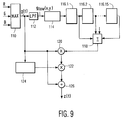
    10. An analog circuit for providing dynamic gamma contrast control of a video signal in a television receiver, said circuit comprising:
      an input for receiving input R, G, B signals;
      means for determining a maximum, pixel-by-pixel of the input R, G, B signals forming the signal g(t);
      means for low-pass filtering the signal g(t);
      means for sampling an output of the low-pass filtering means;
      delaying means for delaying an output of said sampling means, said delaying means having a plurality of stages each of which having an output;
      means for summing the outputs from said plurality of stages in said delaying means;
      a first multiplier having a first input coupled to the output of said summing means and a second input coupled to the output of said maximum determining means;
      a nonlinear circuit having an input coupled to the output of said maximum determining means;
      a second multiplier having a first input coupled to an output of said first multiplier and a second input coupled to an output of said nonlinear circuit;
      a divider coupled to an output of said second multiplier and the output of said maximum determining means for forming the function z(x,y); and
      means for receiving the input R, G, B signals and for multiplying these signals by the function z(x,y).
    EP94201620A 1993-06-14 1994-06-07 Dynamic gamma contrast control Expired - Lifetime EP0630160B1 (en)

    Applications Claiming Priority (2)

    Application Number Priority Date Filing Date Title
    US08/076,565 US5394195A (en) 1993-06-14 1993-06-14 Method and apparatus for performing dynamic gamma contrast control
    US76565 1998-05-12

    Publications (3)

    Publication Number Publication Date
    EP0630160A2 EP0630160A2 (en) 1994-12-21
    EP0630160A3 EP0630160A3 (en) 1997-01-02
    EP0630160B1 true EP0630160B1 (en) 2000-03-22

    Family

    ID=22132830

    Family Applications (1)

    Application Number Title Priority Date Filing Date
    EP94201620A Expired - Lifetime EP0630160B1 (en) 1993-06-14 1994-06-07 Dynamic gamma contrast control

    Country Status (4)

    Country Link
    US (1) US5394195A (en)
    EP (1) EP0630160B1 (en)
    JP (1) JPH07143358A (en)
    DE (1) DE69423541T2 (en)

    Families Citing this family (37)

    * Cited by examiner, † Cited by third party
    Publication number Priority date Publication date Assignee Title
    JP3501252B2 (en) * 1995-06-16 2004-03-02 三菱電機株式会社 Gradation correction device
    US5909249A (en) * 1995-12-15 1999-06-01 General Instrument Corporation Reduction of noise visibility in a digital video system
    EP0967809A1 (en) * 1998-06-22 1999-12-29 Deutsche Thomson-Brandt Gmbh Gamma matching of a video processor by means of three measured currents
    US6449389B1 (en) * 1999-09-24 2002-09-10 Xerox Corporation Method and apparatus for single channel color image segmentation using local context based adaptive weighting
    US6633343B2 (en) * 2000-03-14 2003-10-14 Matsushita Electric Industrial Co., Ltd. Dynamic gamma correction apparatus
    US7064740B2 (en) * 2001-11-09 2006-06-20 Sharp Laboratories Of America, Inc. Backlit display with improved dynamic range
    KR100590529B1 (en) * 2003-11-04 2006-06-15 삼성전자주식회사 Method and apparatus for enhancing local luminance of image, and computer-readable recording media for storing computer program
    US7623105B2 (en) 2003-11-21 2009-11-24 Sharp Laboratories Of America, Inc. Liquid crystal display with adaptive color
    CN1890989B (en) * 2003-12-18 2012-08-08 夏普株式会社 Dynamic gamma for a liquid crystal display
    JP4497959B2 (en) 2004-03-05 2010-07-07 キヤノン株式会社 Video signal processing apparatus and video signal processing method
    US7612757B2 (en) * 2004-05-04 2009-11-03 Sharp Laboratories Of America, Inc. Liquid crystal display with modulated black point
    US7602369B2 (en) * 2004-05-04 2009-10-13 Sharp Laboratories Of America, Inc. Liquid crystal display with colored backlight
    US7532192B2 (en) * 2004-05-04 2009-05-12 Sharp Laboratories Of America, Inc. Liquid crystal display with filtered black point
    US7505018B2 (en) * 2004-05-04 2009-03-17 Sharp Laboratories Of America, Inc. Liquid crystal display with reduced black level insertion
    US7872631B2 (en) * 2004-05-04 2011-01-18 Sharp Laboratories Of America, Inc. Liquid crystal display with temporal black point
    US20050248553A1 (en) * 2004-05-04 2005-11-10 Sharp Laboratories Of America, Inc. Adaptive flicker and motion blur control
    US7777714B2 (en) * 2004-05-04 2010-08-17 Sharp Laboratories Of America, Inc. Liquid crystal display with adaptive width
    US8395577B2 (en) * 2004-05-04 2013-03-12 Sharp Laboratories Of America, Inc. Liquid crystal display with illumination control
    US7023451B2 (en) * 2004-06-14 2006-04-04 Sharp Laboratories Of America, Inc. System for reducing crosstalk
    US7556836B2 (en) * 2004-09-03 2009-07-07 Solae, Llc High protein snack product
    US7898519B2 (en) * 2005-02-17 2011-03-01 Sharp Laboratories Of America, Inc. Method for overdriving a backlit display
    TWI326443B (en) * 2004-10-27 2010-06-21 Chunghwa Picture Tubes Ltd Dynamic gamma correction circuit, method thereof and plane display device
    US7525528B2 (en) * 2004-11-16 2009-04-28 Sharp Laboratories Of America, Inc. Technique that preserves specular highlights
    US8050512B2 (en) 2004-11-16 2011-11-01 Sharp Laboratories Of America, Inc. High dynamic range images from low dynamic range images
    US8050511B2 (en) * 2004-11-16 2011-11-01 Sharp Laboratories Of America, Inc. High dynamic range images from low dynamic range images
    US9143657B2 (en) * 2006-01-24 2015-09-22 Sharp Laboratories Of America, Inc. Color enhancement technique using skin color detection
    US8121401B2 (en) * 2006-01-24 2012-02-21 Sharp Labortories of America, Inc. Method for reducing enhancement of artifacts and noise in image color enhancement
    KR100809347B1 (en) 2006-07-31 2008-03-05 삼성전자주식회사 Method and apparatus for compensating shadow area
    US8941580B2 (en) * 2006-11-30 2015-01-27 Sharp Laboratories Of America, Inc. Liquid crystal display with area adaptive backlight
    KR100866486B1 (en) 2007-01-04 2008-11-03 삼성전자주식회사 Ambient light adaptive color correction method and device for projector
    JP5241031B2 (en) * 2009-12-08 2013-07-17 ルネサスエレクトロニクス株式会社 Display device, display panel driver, and image data processing device
    DE102011055269A1 (en) * 2011-11-11 2013-05-16 Jenoptik Robot Gmbh Method for performing dynamic compression in traffic photography
    US9324137B2 (en) * 2012-10-24 2016-04-26 Marvell World Trade Ltd. Low-frequency compression of high dynamic range images
    JP5574015B2 (en) * 2013-05-27 2014-08-20 株式会社ニコン Image processing apparatus, electronic camera, and image processing program
    EP3195251B1 (en) * 2014-09-19 2019-01-23 Barco N.V. Method to enhance contrast with reduced visual artifacts
    CN113900147A (en) * 2020-07-06 2022-01-07 中国石油天然气股份有限公司 Sand dune ringing suppression method and system
    CN112532958B (en) * 2020-11-24 2022-09-06 海宁奕斯伟集成电路设计有限公司 Image processing method, device, electronic equipment and readable storage medium

    Family Cites Families (5)

    * Cited by examiner, † Cited by third party
    Publication number Priority date Publication date Assignee Title
    DE2921246A1 (en) * 1979-05-25 1980-12-04 Bosch Gmbh Robert METHOD AND CIRCUIT FOR CONTRAST CORRECTION OF COLOR TELEVISION SIGNALS
    JPS56107674A (en) * 1980-01-31 1981-08-26 Sony Corp Gradation correcting device of video signal
    US4667228A (en) * 1983-10-14 1987-05-19 Canon Kabushiki Kaisha Image signal processing apparatus
    EP0278137B1 (en) * 1987-02-11 1992-12-02 Digivision, Inc. Real-time, localized enhancement of a video image using separable two-dimensional filters
    US4829381A (en) * 1988-04-18 1989-05-09 Polaroid Corporation System and method for electronic image enhancement by dynamic pixel transformation

    Also Published As

    Publication number Publication date
    DE69423541D1 (en) 2000-04-27
    EP0630160A2 (en) 1994-12-21
    US5394195A (en) 1995-02-28
    JPH07143358A (en) 1995-06-02
    DE69423541T2 (en) 2000-09-21
    EP0630160A3 (en) 1997-01-02

    Similar Documents

    Publication Publication Date Title
    EP0630160B1 (en) Dynamic gamma contrast control
    US6724943B2 (en) Device and method for image processing
    US7551794B2 (en) Method apparatus, and recording medium for smoothing luminance of an image
    US5237402A (en) Digital image processing circuitry
    JP3828251B2 (en) Video dynamic range expansion device
    US6965416B2 (en) Image processing circuit and method for processing image
    JP5003196B2 (en) Image processing apparatus and method, and program
    RU2146425C1 (en) Method and circuits to raise definition ( versions )
    CN100366052C (en) Image processing device and method
    US20050226526A1 (en) Image processing device and method
    JP2007049540A (en) Image processing apparatus and method, recording medium, and program
    JP2001298621A (en) Image processor and image processing method
    US7561189B2 (en) Method and apparatus of image dynamic response re-mapping and digital camera using the same
    AU767050B2 (en) Contour correction device
    JP3293951B2 (en) Apparatus and method for limiting gain in a digital gamma corrector
    US20090002562A1 (en) Image Processing Device, Image Processing Method, Program for Image Processing Method, and Recording Medium Having Program for Image Processing Method Recorded Thereon
    JP3184309B2 (en) Gradation correction circuit and imaging device
    KR20010075557A (en) Video signal enhancement
    JP3201049B2 (en) Gradation correction circuit and imaging device
    JP2003348377A (en) Image display device and image processing apparatus, and image processing method
    JP4174656B2 (en) Image display device, image processing device, and image processing method
    JP2015211320A (en) Image processing apparatus, control method thereof and program
    JP2935389B2 (en) Video signal processing device and nonlinear signal processing device
    JPH09224186A (en) Video camera and control correcting device
    JPH0646293A (en) Contour correction device

    Legal Events

    Date Code Title Description
    PUAI Public reference made under article 153(3) epc to a published international application that has entered the european phase

    Free format text: ORIGINAL CODE: 0009012

    AK Designated contracting states

    Kind code of ref document: A2

    Designated state(s): DE FR GB

    PUAL Search report despatched

    Free format text: ORIGINAL CODE: 0009013

    AK Designated contracting states

    Kind code of ref document: A3

    Designated state(s): DE FR GB

    17P Request for examination filed

    Effective date: 19970702

    GRAG Despatch of communication of intention to grant

    Free format text: ORIGINAL CODE: EPIDOS AGRA

    17Q First examination report despatched

    Effective date: 19990517

    GRAG Despatch of communication of intention to grant

    Free format text: ORIGINAL CODE: EPIDOS AGRA

    GRAG Despatch of communication of intention to grant

    Free format text: ORIGINAL CODE: EPIDOS AGRA

    GRAH Despatch of communication of intention to grant a patent

    Free format text: ORIGINAL CODE: EPIDOS IGRA

    GRAH Despatch of communication of intention to grant a patent

    Free format text: ORIGINAL CODE: EPIDOS IGRA

    GRAA (expected) grant

    Free format text: ORIGINAL CODE: 0009210

    AK Designated contracting states

    Kind code of ref document: B1

    Designated state(s): DE FR GB

    PG25 Lapsed in a contracting state [announced via postgrant information from national office to epo]

    Ref country code: FR

    Free format text: THE PATENT HAS BEEN ANNULLED BY A DECISION OF A NATIONAL AUTHORITY

    Effective date: 20000322

    REF Corresponds to:

    Ref document number: 69423541

    Country of ref document: DE

    Date of ref document: 20000427

    PG25 Lapsed in a contracting state [announced via postgrant information from national office to epo]

    Ref country code: GB

    Free format text: LAPSE BECAUSE OF NON-PAYMENT OF DUE FEES

    Effective date: 20000622

    ET Fr: translation filed
    PLBE No opposition filed within time limit

    Free format text: ORIGINAL CODE: 0009261

    STAA Information on the status of an ep patent application or granted ep patent

    Free format text: STATUS: NO OPPOSITION FILED WITHIN TIME LIMIT

    GBPC Gb: european patent ceased through non-payment of renewal fee

    Effective date: 20000622

    26N No opposition filed
    PG25 Lapsed in a contracting state [announced via postgrant information from national office to epo]

    Ref country code: DE

    Free format text: LAPSE BECAUSE OF NON-PAYMENT OF DUE FEES

    Effective date: 20010403