EP0630096A1 - Motive power generating device - Google Patents
Motive power generating device Download PDFInfo
- Publication number
- EP0630096A1 EP0630096A1 EP93304620A EP93304620A EP0630096A1 EP 0630096 A1 EP0630096 A1 EP 0630096A1 EP 93304620 A EP93304620 A EP 93304620A EP 93304620 A EP93304620 A EP 93304620A EP 0630096 A1 EP0630096 A1 EP 0630096A1
- Authority
- EP
- European Patent Office
- Prior art keywords
- magnetic
- electromagnets
- permanent magnet
- output shaft
- magnetic body
- Prior art date
- Legal status (The legal status is an assumption and is not a legal conclusion. Google has not performed a legal analysis and makes no representation as to the accuracy of the status listed.)
- Granted
Links
Images


Classifications
-
- H—ELECTRICITY
- H02—GENERATION; CONVERSION OR DISTRIBUTION OF ELECTRIC POWER
- H02K—DYNAMO-ELECTRIC MACHINES
- H02K21/00—Synchronous motors having permanent magnets; Synchronous generators having permanent magnets
- H02K21/12—Synchronous motors having permanent magnets; Synchronous generators having permanent magnets with stationary armatures and rotating magnets
- H02K21/14—Synchronous motors having permanent magnets; Synchronous generators having permanent magnets with stationary armatures and rotating magnets with magnets rotating within the armatures
- H02K21/20—Synchronous motors having permanent magnets; Synchronous generators having permanent magnets with stationary armatures and rotating magnets with magnets rotating within the armatures having windings each turn of which co-operates only with poles of one polarity, e.g. homopolar machine
-
- H—ELECTRICITY
- H02—GENERATION; CONVERSION OR DISTRIBUTION OF ELECTRIC POWER
- H02K—DYNAMO-ELECTRIC MACHINES
- H02K29/00—Motors or generators having non-mechanical commutating devices, e.g. discharge tubes or semiconductor devices
- H02K29/06—Motors or generators having non-mechanical commutating devices, e.g. discharge tubes or semiconductor devices with position sensing devices
- H02K29/10—Motors or generators having non-mechanical commutating devices, e.g. discharge tubes or semiconductor devices with position sensing devices using light effect devices
-
- H—ELECTRICITY
- H02—GENERATION; CONVERSION OR DISTRIBUTION OF ELECTRIC POWER
- H02K—DYNAMO-ELECTRIC MACHINES
- H02K41/00—Propulsion systems in which a rigid body is moved along a path due to dynamo-electric interaction between the body and a magnetic field travelling along the path
- H02K41/02—Linear motors; Sectional motors
Definitions
- This invention relates to a motive power generating device in which electromagnets and a combination of a magnetic material and a permanent magnet are used as a stator and a rotator, respectively. More particularly, the invention relates to a motive power generating device which transforms magnetic energy into operative energy with maximum efficiency utilizing a magnetic force inherent in a permanent magnet as an energy source.
- a motive power generating device in which electromagnets and a combination of a magnetic material, such as soft steel, and a permanent magnet are used as a stator and a rotator, respectively.
- a device includes, for example, a step motor of a HB (Hybrid) type.
- Figs. 12 to 17 diagrammatically illustrate an example of conventional HB type step motors.
- the HB type motor is characterized by a rotor 52, as shown in Figs. 12 and 13.
- the rotor combines the advantageous feature of a step motor of a VR (Variable Reluctance) type in that a smaller step angle may be obtained by virtue of the teeth formed in a laminated steel plate 53 constituting one component of the rotor, with the advantageous feature of a step motor of a PM (Permanent Magnet) type in that a high degree of efficiency and miniaturization may be obtained by virtue of the permanent magnet 54 constituting the other component of the rotor 52.
- the steel core of the stator 50 is the same as that of a VR type motor, but the method of winding and connecting the coils is different.
- Fig. 14 shows a passage of magnetic flux (magnetic path) created by the permanent magnet 54.
- the magnetic path represents a distribution of a uni-polar type in which an N-pole or S-pole uniformly appears at the axial ends of a rotor shaft 55.
- Fig. 15 shows a magnetic path created by the electromagnets 51 of the rotor 50.
- the magnetic path represents a distribution of a hetero-polar type in which an even number of magnetic poles in the order, for example, of NSNS... appear in a plate vertical to the rotor shaft 55.
- the uni-polar magnetic flux of the permanent magnet (magnetic field of the permanent magnet) and the hetero-polar magnetic flux of the windings (magnetic field of the electromagnet) interact with each other so as to generate a torque.
- the term "interaction between the magnetic flux of the permanent magnet and the magnetic flux of the windings" is used herein to mean that an inclination of the line of magnetic force is created in the gap between the permanent magnet 54 and the electromagnet 51.
- FIG. 16 shows a cross-section of S-side (south pole side) of the permanent magnet 54
- Fig. 17 shows a cross-section of N-side (north pole side) of the permanent magnet.
- magnetic flux emanating from the electromagnets 51 is shown by solid lines
- magnetic flux emanating from the permanent magnet 54 is shown by dotted lines.
- the S-side cross-section of the permanent magnet 54 shows that the line of magnetic force in the central gap is inclined in the downward and right hand direction, while the line of magnetic force in the right hand end gap is inclined in the upward and right-hand direction.
- the lines of magnetic force in the above two gaps tend to cancel each other out.
- the same relationship is applied to the cross section of the N-side (north pole side) of the permanent magnet 54.
- torque will be generated when the magnetic field of the electromagnet 51 and the magnetic field of the permanent magnet 54 interact with each other.
- the magnetic field of the electromagnet 51 and the magnetic field of the permanent magnet 54 interact with each other strongly in the same direction so as to generate in the rotor 52 a propulsive force toward the left in Fig. 16.
- both magnetic fields interact with each other weakly in opposite directions, so as to generate a propulsive force toward the right in Fig. 16. It is noted, however, that the propulsive force generated toward the right in Fig. 16 is relatively small. Consequently, a stronger propulsive force toward the left in Fig. 16 is generated.
- the magnetic field of the electromagnet 51 and the magnetic field of the permanent magnet 54 interact with each other weakly in opposite directions, so as to generate in the rotor 52 a propulsive force toward the right in Fig. 17.
- the resultant propulsive force is relatively small.
- both magnetic field interact strongly with each other in the same direction, so as to generate a propulsive force of relatively significant magnitude toward the left in Fig. 17. Consequently, a stronger propulsive force toward the left in Fig. 17 will be generated. Accordingly, the thus generated propulsive force causes the rotor to be advanced in the left-hand direction in Figs. 16 and 17.
- the first invention comprises a permanent magnet disposed around a rotational output shaft for rotation therewith, the output shaft being mounted on a support member for rotation, a magnetic body disposed in concentric relationship with the permanent magnet for rotation with the rotational output shaft, the magnetic body being subjected to the magnetic flux of the permanent magnet, a plurality of electromagnets fixedly mounted to the support member in such a manner that they are spaced a predetermined distance around the periphery of the magnetic material, each magnetic circuit of the electromagnets being adapted to be independent of one another and the excitation change-over means of the electromagnets, the excitation change-over means being adapted to sequentially magnetize one of the electromagnets which is positioned forwardly with regard to a rotational direction of the rotational output shaft, so as to impart to the electromagnet a magnetic polarity magnetically opposite to that of the magnetic pole of the permanent magnet, whereby a magnetic flux passing through the magnetic body converges in one direction thereby applying a rotational torque to
- the first invention when one of the electromagnets which is positioned forwardly in the rotational direction of the rotational output shaft, a magnetic field created by the excited electromagnet and a magnetic field created by the permanent magnet interact with each other.
- the magnetic flux passing through the magnetic body converges toward the exited electromagnet, so as to rotate the rotational output shaft by a predetermined angle toward the excited electromagnet.
- the above excited electromagnet is de-magnetized, and another electromagnet currently positioned forwardly in the rotational direction of the rotational output shaft is excited or magnetized. Sequential excitation of the electromagnets in the above manner permits rotation of the output shaft in a predetermined direction.
- the electromagnets are excited to have a magnetic polarity opposite to that of the magnetic pole of the permanent magnet and that the magnetic circuit of the excited electromagnets is independent from those of adjacent electromagnets.
- the magnetic flux generated by the excited electromagnet is prevented from passing through magnetic circuits of adjacent electromagnets, which, if it occurs, might cause the electromagnets to be magnetized to have the same polarity as that of the magnetic pole of the permanent magnet. Accordingly, no objectionable force will be generated which might interfere with rotation of the output shaft.
- the second invention comprises a permanent magnet mounted on a movable body arranged movably along a linear track, a magnetic body mounted on the permanent magnet, the magnetic body being subjected to a magnetic flux of the permanent magnet, a plurality of electromagnets spaced an appropriate distance along the linear track, said electromagnets having respective magnetic circuits which are independent of one another and excitation change-over means of the electromagnets, said excitation change-over means being adapted to sequentially magnetize one of the electromagnets which is positioned forwardly with respect to the direction of movement of the movable body, so as to impart to the excited electromagnet a magnetic polarity opposite to that of the magnetic pole of the permanent magnet, whereby a magnetic flux passing through the magnetic body converges in a predetermined direction so as to cause linear movement of the movable body.
- the electromagnet positioned forwardly of the forward end of the movable body with regard to the direction of the movement of the movable body is excited, a magnetic field generated by the excited electromagnet and magnetic field generated by the permanent magnet interact with each other.
- a magnetic flux passing through the magnetic body converges toward the excited electromagnet, so as to displace the movable body a predetermined distance toward the excited electromagnet.
- the movable body has been moved the predetermined distance, the movable body is positioned below the above excited electromagnet, and another electromagnet is positioned forwardly of the forward end of the movable body.
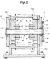
- a rotational output shaft 11 is rotatably mounted between front and rear side plates 10a of a support member 10 through bearings 11a, as shown in Figs. 1 and 2.
- Permanent magnets 13 in a ring form are freely fitted over the output shaft at the axially opposite ends thereof and axially inward of the respective side plates 10a for movement with the rotational output shaft 11.
- the permanent magnets are magnetized in the axial direction.
- a magnetic body 14 is fixedly mounted between each of the side plates 10a for the rotational output shaft 11 and the permanent magnets 13.
- Each magnetic body 14 includes alternately disposed notches 14a and magnetic teeth 14b. It is noted that flux of the permanent magnets 13 passes through the respective magnetic bodies 14.
- the magnetic body 14 is provided, for example, with three notches 14a and three magnetic teeth 14b.
- the permanent magnets 13 and magnetic bodies 14 are disposed coaxially with the rotational output shaft 11.
- the corresponding permanent magnets 13 and magnetic bodies 14 are combined together by means of connecting means such as bolts 15 so as to form a rotor 12.
- the rotor 12 is adapted to be rotated in unison with the rotational output shaft 11.
- the support member 10 and rotational output shaft 11 are both made from a non-magnetic material.
- the support member 10 may be formed, for example, from stainless steel, aluminum alloys, or synthetic resins, while the rotational output shaft 11 may be formed from stainless steel, for example.
- the magnetic circuit formed by the permanent magnet 13 and magnetic body at one axial end of the rotational output shaft 11 and the magnetic circuit formed by the permanent magnet 13 and magnetic body at the opposite axial end of the output shaft are independent of one another.
- the magnetic bodies 14 may be formed from magnetic materials having a high magnetic permeability, such as various kinds of steel materials, silicon steel plate, permalloys, or the like.
- a plurality of electromagnets 16a through 16l, constituting the stator, are disposed between the side plates 10a.
- the electromagnets are equidistantly and fixedly disposed around the magnetic materials 14 so that they surround the magnetic bodies.
- twelve (12) electromagnets may be disposed.
- the magnetic circuit of each of the electromagnets 16a through 16l is adapted to be independent from one another, so that no flux of magnetized electromagnets passes through the iron core of adjacent electromagnets.
- each of the electromagnets 16a through 16l extends in parallel with the axial direction of the rotational output shaft 11, permanent magnets 13 and magnetic bodies 14.
- the axially opposite ends (magnetic polar portion) of each of the iron cores are oppositely disposed relative to the peripheral surface of the magnetic bodies with a slight gap therebetween.
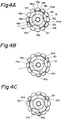
- electromagnets 16a through 16l are disposed at a position corresponding to boundary portions 14c1 through 14c6 between the notch 14a and the magnetic tooth 14b.
- electromagnets 16a, 16b, 16e, 16f, 16i and 16j are positioned in an opposite relationship to the boundary portions 14c1, 14c2, 14c3, 14c4, 14c5, and 14c6, respectively.
- Fig. 5A shows a path of magnetic flux created by the permanent magnet 13 when the electromagnets are not excited or magnetized
- Fig. 5B shows a path of magnetic flux created by the permanent magnet 13 and a path of magnetic flux created by the windings of the electromagnets when the electromagnets are magnetized.
- both paths of magnetic flux represent a uni-polar distribution in which N-pole or S-pole evenly appears at the opposite axial ends.
- Excitation change-over means 17 for sequentially exciting or magnetizing the electromagnets 16a through 16l is basically consisted of a conventional excitation circuit for supplying direct current to each windings of the electromagnets 16a through 16l.
- the change-over portion for changing electric feed to the electromagnets 16a through 16l includes a plurality of optical sensors 18 and a light shield plate 19 for turning the optical sensors ON and OFF.
- the optical sensors 18 are spaced apart from one another with a space therebetween for permitting the light shield plate 19 to pass through a light emitting element and a light receiving element.
- the optical sensors 18 are disposed in the outer surface of one of the side plates 10a in equidistal relationship in the circumferential direction thereof, so that they are positioned to correspond to the electromagnets 16a through 16l (for example, the optical sensor 18 is shown to be disposed in the outer surface of the rear side plate).
- the light shielding plate 19 is fixed to the rotational output shaft 11 at the end thereof, the light shielding plate protruding from the rear side plate 10a on which the optical sensors are disposed.
- the electromagnet corresponding to such optical sensor 18 is supplied with electricity.
- the electromagnets 16a through 16l When the electromagnets 16a through 16l are not supplied with electricity by means of the excitation change-over means 17, the electromagnets 16c, 16d, 16g, 16h, 16k and 16l opposed to the magnetic teeth 14b with a small gap therebetween merely serve as a magnetic material disposed within the magnetic field of the permanent magnet 13 (refer to shaded portion in Fig. 4A), so as to absorb the magnetic teeth 14b thereto, and the rotor 12 remains stationary.
- the electromagnets 16a, 16e and 16i positioned adjacent to the boundary portion 14c1, 14c3 and 14c5 formed between the respective notches 14a and the magnetic teeth 14b are magnetized or excited simultaneously by means of the excitation change-over means, as shown in Fig. 4B, the magnetic field of the permanent magnet 13 and the magnetic fields of the electromagnets 16a, 16e and 16i interact with each other, so that a magnetic flux 14d passing through the magnetic body 14 instantaneously converges to the electromagnets 16a, 16e, and 16i.
- the rotor 12 is imparted with a rotational torque in a direction in which the magnetic flux 14d will be widened, i.e., counter-clockwise direction as viewed in Fig. 4B.
- Figs. 4C through 4G illustrate change in the width of the magnetic flux 14d in accordance with rotation of the rotor 12.
- the width of the magnetic flux becomes maximized, i.e., when only the magnetic teeth 14b are opposed to the electromagnets 16a, 16e and 16i, while the notches 14a are displaced completely away from the electromagnets 16a, 16e and 16i, the width of the magnetic flux 14d is maximized.
- an absorption force acting between the permanent magnet 13 and the electromagnets 16a, 16e and 16i is maximized.
- the rotational torque acting on the rotor 12 becomes zero.
- the electromagnets 16a, 16e and 16i are de-magnetized and the electromagnets 16b, 16f and 16j are excited or magnetized by means of the excitation change-over means 17.
- the magnetic flux 14d converges toward the electromagnets 16b, 16f and 16j, as shown in Fig. 4H, so that a rotational torque acts upon the rotor, as described above.
- the electromagnets 16c, 16g and 16k are excited.
- the boundary portion 14c1, 14c3 and 14c5 approach another electromagnets 16d, 16h and 16l positioned forwardly in regard to the rotational direction, in response to rotation of the rotor 12, the electromagnets 16c, 16g and 16k are de-magnetized and the electromagnets 16d, 16h and 16l are energized or excited.
- a rotational torque is generated between one of the magnetic poles of the permanent magnet 13 (for example, N-pole) and the magnetic poles (for example, S-poles) of the electromagnets 16a through 16l positioned at their respective axial ends.
- a rotational torque is also generated between the other magnetic pole (for example, S-pole) of the permanent magnet 13 and the other magnetic pole (for example, N-pole) of each of the electromagnets 16a through 16l positioned at the other axial end.
- certain of the electromagnets 16a through 16l are magnetized only to S-pole, thus preventing formation of a magnetic circuit, due to passage of magnetic flux from the excited electromagnets through adjacent electromagnets, which tends to bring about N-poles magnetically similar to the permanent magnet 13.
- certain of the electromagnets are magnetized only to N-pole, thus preventing formation of a magnetic circuit, due to passage of magnetic flux from the excited electromagnets through adjacent electromagnets, which tends to bring about S-poles magnetically similar to the permanent magnet 13.
- the magnetic flux of the permanent magnet 13 passes through the magnetic bodies 14 so as to be converged to the excited electromagnets (refer to the magnetic flux 14d shown in Figs. 4 through 4H), thus forming dead zones, through which no magnetic flux passes, in the magnetic bodies 14 at a position opposite to the un-excited electromagnets. Accordingly, no force is generated which tends to prevent rotation of the rotor 12.
- the notches 14a and the magnetic teeth 14b are alternately disposed in the outer periphery of the magnetic materials 14, and the electromagnets are disposed at a position each corresponding to the boundary portions between the notches and the magnetic teeth, it is possible for the line of the magnetic force, generated in each gap between the boundary portions and the electromagnets when the electromagnets are excited, to be inclined to a substantial degree, so that a sufficient degree of rotational torque may be obtained upon initial excitation of the electromagnets.
- Pure steel was used as a magnetic material.
- the magnetic material was 30 mm in thickness and formed to have magnetic teeth of 218 mm diameter and notches of 158 mm diameter.
- a ferritic magnet was used as a permanent magnet.
- the magnetic force of the magnet was 1,000 gauss. Electric power of 19.55 watts was applied to the electromagnets at 17 volts and 1.15 amperes. Under the above condition, a rotational number of 100 rpm, a torque of 60.52 Kg-cm and an output of 62,16 watt were obtained.
- each electromagnet 160 to form the stator comprises an iron core 161 having a pair of legs 162 disposed at opposite axial ends thereof and extending toward the outer periphery of the magnetic bodies (outer periphery of the magnetic teeth 14b), each of the legs being wound with respective coils 163.
- the remaining components are basically identical to those in the motor shown in Figs. 1 through 3.
- the components similar to those in Figs. 1 through 3 are denoted by like reference numerals.
- each coil 163 is supplied with electricity so that one leg 162 disposed at one axial end (left-hand side in Fig.
- each of the iron cores 161 is magnetized to be S-pole which is magnetically opposite to the magnetic pole (N-pole) of the confronting magnetic body 14, while the leg 162 disposed at the other end of each of the iron cores is magnetized to be N-pole which is magnetically opposite to the magnetic pole (S-pole) of the confronting magnetic body 14.
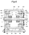
- FIG. 7 An alternative embodiment shown in Fig. 7 is similar to the motor shown in Figs. 1 through 3, with the exception that: an additional magnetic body 14 is mounted on the rotational output shaft 11 at the axial midpoint thereof; two permanent magnets 130 are freely mounted on the output shaft 11 in a manner shown in Fig. 6; and each iron core 165 is provided with three legs 166 positioned at the opposite axial ends and midpoint thereof and extending toward the respective outer periphery of the magnetic bodies, with the legs 166 positioned at axial opposite ends of the respective iron cores 165 being wound with a coil 167, whereby forming electromagnets 164.
- the remaining components are substantially the same as those in the motor shown in Figs. 1 through 3. It is noted here that the rotational output shaft 11 may be formed from magnetic materials or non-magnetic materials.
- each of the coils 167 is supplied with electricity so that the legs 166 positioned at the opposite axial ends of each of the iron cores 164 is magnetized to be S-pole which is magnetically opposite to the magnetic pole (N-pole) of the confronting magnetic body 14.
- the leg 166 positioned at the midpoint of the iron core 165 is magnetized to be N-pole which is magnetically opposite to the magnetic pole (S-pole) of the confronting magnetic body 14.
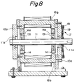
- a further embodiment shown in Fig. 8 is similar to the motor shown in Figs. 1 though 3, with the exception that a permanent magnet magnetized in the radial direction, rather than in the axial direction is employed.
- the permanent magnet 131 of an annular configuration has, for example, N-pole in the outer periphery and S-pole in the inner periphery.
- the permanent magnet 131 is received within a cavity 14e provided in the respective magnetic body 14 at the intermediate portion thereof as disposed at the opposite axial ends of the rotational output shaft 11.
- the remaining components are identical to those in the motor shown in Figs. 1 to 3.
- the components identical to those in the motor shown in Figs. 1 to 3 are denoted by the same reference numerals. It is noted that this embodiment may also employ the electromagnets 160 shown in Fig. 6.
- the rotational output shaft 11 may be formed from magnetic materials, rather than non-magnetic materials.
- FIG. 9 Further embodiment shown in Fig. 9 is similar to the motor shown in Figs. 1 to 3, with three exceptions.
- the first exception is that a permanent magnet magnetized in the radial direction, rather than in the axial direction is employed.
- the permanent magnet 131 having an annular configuration has, for example, N-pole in the outer periphery and S-pole in the inner periphery.
- the permanent magnet 131 is received within a cavity 14e provided in the respective magnetic body 14 at the intermediate portion thereof as disposed at the axial opposite ends of the rotational output shaft 11.
- the second exception is that an additional magnetic body 14 is disposed at the axial midpoint of the rotational output shaft 11.
- the iron core 165 is provided with three legs 166 disposed at the axial opposite ends and the midpoint thereof, respectively, and extending toward the outer periphery of the magnetic body 14, with the legs positioned at the opposite axial ends being wound with respective coils so as to form an electromagnet 164.
- the remaining components are identical to those in the motor shown in Figs. 1 to 3.
- the components identical to those in the motor shown in Figs. 1 to 3 are denoted by the same reference numerals.
- each coil is supplied with electricity so that the legs 166 disposed at opposite axial ends of the iron core 165 are magnetized to be S-pole which is magnetically opposite to the magnetic pole (N-pole) of the confronting magnetic body 14.
- the leg 166 disposed at the midpoint of the iron core 165 is magnetized to be N-pole which is magnetically opposite to the magnetic pole (S-pole) of the confronting magnetic body 14.
- the rotational output shaft 11 may be formed from magnetic materials rather than non-magnetic materials. With this embodiment, it is possible to obtain the same effect as that obtained with the embodiment shown in Fig. 7.
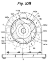
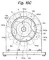
- FIG. 10A to 10C are similar to the motor shown in Figs. 1 to 3, with the exception that: like the embodiments shown in Figs. 8 and 9, an annular permanent magnet 131 is employed which is received in a cavity 140e provided in the central portion 140 of the magnetic body 140; the magnetic body 140 is provided with notches 140a in the outer peripheral portion thereof, so that the gap G between the magnetic body 140 and the electromagnet becomes gradually broader in the rotational direction of the rotor; and the electromagnets confronting to the gap G with an intermediate width as positioned between the electromagnets confronting to the gap G with a narrower width and the electromagnets confronting to the gap G with a broader width are excited or magnetized in a sequential manner.
- reference numeral 140d indicates magnetic flux passing through the magnetic body 140, so as to illustrate converged condition of such magnetic flux upon excitation of the electromagnets.
- notches 140a are provided. It is noted, however, that two (2) or three (3) notches may be provided. It is also possible to attach the magnetic material 140 to the rotational output shaft 11 in an eccentric manner in its entirety, without providing notches 140a.
- Figs. 11A through 11H are illustrative diagrams showing the operation of the second embodiment of the invention when developed into a linear motor type.
- a movable body 21 is adapted to be moved along a linear track 20 of a roller conveyor type.
- the track includes a frame on which a plurality of rollers are disposed in parallel relationship relative one another.
- a permanent magnet 22 is mounted on the movable body 21.
- a magnetic body 23 of a plate-like configuration is fixed to the permanent magnet 22 in the upper surface thereof, so as to form a movable element. It is noted that magnetic flux from the permanent magnet 22 passes through the magnetic body 23.
- a plurality of electromagnets 25a, 25b, 25c, 25d and so on are disposed above the movable element 24 along the linear track and in a parallel relationship relative one another.
- the electromagnets constitute a stator 25.
- Magnetic circuits of the electromagnets 25a, 25b, 25c, 25d, and so on, are independent from one another, so that the electromagnets are magnetized in a sequential manner by means of excitation change-over means (not shown), so as to have a magnetic polarity opposite to the magnetic pole of the permanent magnet 22.
- Power output shafts 21a are attached to a side surface of the movable body 21.
- the electromagnets 25a and 25b positioned just above the movable element 24 are subjected to magnetic field of the permanent magnet 22 (refer to shaded portion in Fig. 11A).
- Such electromagnets magnetically absorb the magnetic body 23 thereto, so that the movable element 24 remains to be stopped.
- Figs. 11C through 11E illustrate a change in width of the magnetic flux 23a in response to movement of the movable element 24.
- the width of the magnetic flux 23a becomes maximized i.e., when the forward end of the magnetic material 23 of the movable element 24 is positioned just before passing by the electromagnet 25c, the width of the flux 23 becomes maximized.
- magnetic absorption acting between the permanent magnet 22 and the electromagnet 25c becomes maximized, but the propulsive force acting on the movable element becomes zero.
- the excitation change-over means is actuated so as to stop excitation of the electromagnet 25c and so as to initiate excitation of the electromagnet 25d.
- the magnetic flux 23a converges to the electromagnet 25d, as shown in Fig. 11F, so that a propulsive force acts on the movable element 24, as in the previous stage.
- the sequential excitation of the electromagnets causes interaction between the magnetic fields of permanent magnet 22 and electromagnets, whereby a propulsive force is applied to the movable element 24.
- the electromagnet 25c is magnetized solely to be S-pole, so as to prevent formation of a magnetic circuit by virtue of passage of magnetic flux from the electromagnet 25c through to the adjacent electromagnets 25b and 25d, which formation, if it occurs, tends to cause the polarity of the electromagnets to be N-pole identical to the magnetic pole of the permanent magnet 22. Accordingly, and in a manner similar to that in the first embodiment, no force is generated which tends to interfere with movement of the movable element 24.
- a plurality of electromagnets serving as a stator are so arranged that their respective magnetic circuits become independent from one another.
- the electromagnets are also arranged so that they are solely magnetized or excited to have a magnetic polarity opposite to the magnetic pole of the confronting permanent magnet.
- each electromagnet is prevented from becoming magnetized to the same polarity as that of the permanent magnet, which may occur when magnetic flux from a particular electromagnet passes through to adjacent electromagnets. Accordingly, no force will be exerted which tends to interfere with the intended movement of a rotor or a movable element.
- electric energy applied to the electromagnets may be efficiently utilized, while, at the same time, magnetic energy contained in the permanent magnet may also be efficiently utilized.
- the coils constituting the electromagnets are consistently supplied with electric current with the same polarity, without any change, so that heating of coils may be prevented. Further, it is possible to obviate the problems of vibration and noise which might occur due to a repulsive force being generated when polarity of an electric current supplied to the coils is changed.
Landscapes
- Engineering & Computer Science (AREA)
- Power Engineering (AREA)
- Physics & Mathematics (AREA)
- Chemical & Material Sciences (AREA)
- Combustion & Propulsion (AREA)
- Electromagnetism (AREA)
- Permanent Magnet Type Synchronous Machine (AREA)
- Reciprocating, Oscillating Or Vibrating Motors (AREA)
Abstract
Description
- This invention relates to a motive power generating device in which electromagnets and a combination of a magnetic material and a permanent magnet are used as a stator and a rotator, respectively. More particularly, the invention relates to a motive power generating device which transforms magnetic energy into operative energy with maximum efficiency utilizing a magnetic force inherent in a permanent magnet as an energy source.
- Heretofore, it has been known in the art that a motive power generating device in which electromagnets and a combination of a magnetic material, such as soft steel, and a permanent magnet are used as a stator and a rotator, respectively. Such a device includes, for example, a step motor of a HB (Hybrid) type.
- Figs. 12 to 17 diagrammatically illustrate an example of conventional HB type step motors. The HB type motor is characterized by a
rotor 52, as shown in Figs. 12 and 13. The rotor combines the advantageous feature of a step motor of a VR (Variable Reluctance) type in that a smaller step angle may be obtained by virtue of the teeth formed in a laminatedsteel plate 53 constituting one component of the rotor, with the advantageous feature of a step motor of a PM (Permanent Magnet) type in that a high degree of efficiency and miniaturization may be obtained by virtue of thepermanent magnet 54 constituting the other component of therotor 52. It is to be noted here that the steel core of thestator 50 is the same as that of a VR type motor, but the method of winding and connecting the coils is different. - Fig. 14 shows a passage of magnetic flux (magnetic path) created by the
permanent magnet 54. The magnetic path represents a distribution of a uni-polar type in which an N-pole or S-pole uniformly appears at the axial ends of arotor shaft 55. On the other hand, Fig. 15 shows a magnetic path created by theelectromagnets 51 of therotor 50. The magnetic path represents a distribution of a hetero-polar type in which an even number of magnetic poles in the order, for example, of NSNS... appear in a plate vertical to therotor shaft 55. The uni-polar magnetic flux of the permanent magnet (magnetic field of the permanent magnet) and the hetero-polar magnetic flux of the windings (magnetic field of the electromagnet) interact with each other so as to generate a torque. The term "interaction between the magnetic flux of the permanent magnet and the magnetic flux of the windings" is used herein to mean that an inclination of the line of magnetic force is created in the gap between thepermanent magnet 54 and theelectromagnet 51. - A torque generating mechanism of the HB type motor will be explained with reference to Figs. 16 and 17 illustrating a model developed into a form of a linear motor. Fig. 16 shows a cross-section of S-side (south pole side) of the
permanent magnet 54, while Fig. 17 shows a cross-section of N-side (north pole side) of the permanent magnet. In these drawings, magnetic flux emanating from theelectromagnets 51 is shown by solid lines, and magnetic flux emanating from thepermanent magnet 54 is shown by dotted lines. - With regard to the magnetic field from the electromagnets 51 (refer to the solid line in Figs. 16), the S-side cross-section of the
permanent magnet 54 shows that the line of magnetic force in the central gap is inclined in the downward and right hand direction, while the line of magnetic force in the right hand end gap is inclined in the upward and right-hand direction. Thus, the lines of magnetic force in the above two gaps tend to cancel each other out. The same relationship is applied to the cross section of the N-side (north pole side) of thepermanent magnet 54. - It is noted that torque will be generated when the magnetic field of the
electromagnet 51 and the magnetic field of thepermanent magnet 54 interact with each other. Specifically, and with regard to the central gap in the S-side cross-section of thepermanent magnet 54, i.e., N-side of theelectromagnet 51, the magnetic field of theelectromagnet 51 and the magnetic field of thepermanent magnet 54 interact with each other strongly in the same direction so as to generate in the rotor 52 a propulsive force toward the left in Fig. 16. On the other hand, and with regard to the right-hand gap, i.e., S-side of theelectromagnet 51, both magnetic fields interact with each other weakly in opposite directions, so as to generate a propulsive force toward the right in Fig. 16. It is noted, however, that the propulsive force generated toward the right in Fig. 16 is relatively small. Consequently, a stronger propulsive force toward the left in Fig. 16 is generated. - With regard to the central gap in N-side cross-section of the
permanent magnet 54, i.e., N-side of theelectromagnet 51, the magnetic field of theelectromagnet 51 and the magnetic field of thepermanent magnet 54 interact with each other weakly in opposite directions, so as to generate in the rotor 52 a propulsive force toward the right in Fig. 17. The resultant propulsive force is relatively small. On the other hand, and with regard to the right-hand gap in Fig. 17, i.e., S-side of theelectromagnet 51, both magnetic field interact strongly with each other in the same direction, so as to generate a propulsive force of relatively significant magnitude toward the left in Fig. 17. Consequently, a stronger propulsive force toward the left in Fig. 17 will be generated. Accordingly, the thus generated propulsive force causes the rotor to be advanced in the left-hand direction in Figs. 16 and 17. - It should be noted, however, that such a conventional HB type motor involves a problem in that a force acting in an opposite direction to the torque (a force tending to interfere with rotation of the rotor 52) is generated as mentioned above. In view of electrical energy to be applied to the windings of the
electromagnets 51, an electric current applied to the winding of the right-hand end electromagnet in Fig. 16 and the winding of the central electromagnet in Fig. 17 is merely consumed so as to cancel the magnetic field of the permanent magnet which tends to prevent rotation of therotor 52. Thus, such an electric current does not effectively contribute at all to the movement of therotor 54, thus decreasing energy efficiency. In view of the magnetic energy of thepermanent magnet 54, such energy is utilized together with the magnetic field created by theelectromagnet 51, but it partly interferes with the movement of therotor 52. Thus, magnetic energy of thepermanent magnet 54 is not effectively utilized. - The above problem experienced with the HB type motor applies equally to motive power generation devices in which an electromagnet is used as a stator and soft steel and a permanent magnet is used as a rotor.
- Accordingly, it is an object of the invention to provide a motive power generation device in which the occurrence of a force acting in a direction opposite to the direction of movement of a rotor and/or a stator is prevented, so as to permit efficient use of electric energy to be applied to electromagnets, as well as magnetic energy generated by a permanent magnet.
- In order to achieve the above object, the first invention comprises a permanent magnet disposed around a rotational output shaft for rotation therewith, the output shaft being mounted on a support member for rotation, a magnetic body disposed in concentric relationship with the permanent magnet for rotation with the rotational output shaft, the magnetic body being subjected to the magnetic flux of the permanent magnet, a plurality of electromagnets fixedly mounted to the support member in such a manner that they are spaced a predetermined distance around the periphery of the magnetic material, each magnetic circuit of the electromagnets being adapted to be independent of one another and the excitation change-over means of the electromagnets, the excitation change-over means being adapted to sequentially magnetize one of the electromagnets which is positioned forwardly with regard to a rotational direction of the rotational output shaft, so as to impart to the electromagnet a magnetic polarity magnetically opposite to that of the magnetic pole of the permanent magnet, whereby a magnetic flux passing through the magnetic body converges in one direction thereby applying a rotational torque to the rotational output shaft.
- According to the first invention, when one of the electromagnets which is positioned forwardly in the rotational direction of the rotational output shaft, a magnetic field created by the excited electromagnet and a magnetic field created by the permanent magnet interact with each other. Thus, the magnetic flux passing through the magnetic body converges toward the exited electromagnet, so as to rotate the rotational output shaft by a predetermined angle toward the excited electromagnet. When the rotational output shaft has been rotated by the predetermined angle, the above excited electromagnet is de-magnetized, and another electromagnet currently positioned forwardly in the rotational direction of the rotational output shaft is excited or magnetized. Sequential excitation of the electromagnets in the above manner permits rotation of the output shaft in a predetermined direction. In this regard, it is noted that the electromagnets are excited to have a magnetic polarity opposite to that of the magnetic pole of the permanent magnet and that the magnetic circuit of the excited electromagnets is independent from those of adjacent electromagnets. Thus, the magnetic flux generated by the excited electromagnet is prevented from passing through magnetic circuits of adjacent electromagnets, which, if it occurs, might cause the electromagnets to be magnetized to have the same polarity as that of the magnetic pole of the permanent magnet. Accordingly, no objectionable force will be generated which might interfere with rotation of the output shaft.
- In order to achieve the above object, the second invention comprises a permanent magnet mounted on a movable body arranged movably along a linear track, a magnetic body mounted on the permanent magnet, the magnetic body being subjected to a magnetic flux of the permanent magnet, a plurality of electromagnets spaced an appropriate distance along the linear track, said electromagnets having respective magnetic circuits which are independent of one another and excitation change-over means of the electromagnets, said excitation change-over means being adapted to sequentially magnetize one of the electromagnets which is positioned forwardly with respect to the direction of movement of the movable body, so as to impart to the excited electromagnet a magnetic polarity opposite to that of the magnetic pole of the permanent magnet, whereby a magnetic flux passing through the magnetic body converges in a predetermined direction so as to cause linear movement of the movable body.
- According to the second invention, when the electromagnet positioned forwardly of the forward end of the movable body with regard to the direction of the movement of the movable body is excited, a magnetic field generated by the excited electromagnet and magnetic field generated by the permanent magnet interact with each other. Thus, a magnetic flux passing through the magnetic body converges toward the excited electromagnet, so as to displace the movable body a predetermined distance toward the excited electromagnet. When the movable body has been moved the predetermined distance, the movable body is positioned below the above excited electromagnet, and another electromagnet is positioned forwardly of the forward end of the movable body. When this occurs, excitation of the electromagnet positioned above the movable body is interrupted, and excitation of the electromagnet now positioned forwardly of the forward end of the movable body is initiated. Sequential excitation of the electromagnets in the above manner permits movement of the movable body in a predetermined direction. It is noted that no objectionable force which would interfere with movement of the movable body is created for the same reason as that explained in relation to the first invention.
- Fig. 1 is a front elevational view, partly in section and partly omitted, of a motor according to a first embodiment of the invention;
- Fig. 2 is a sectional view along line II-II in Fig. 1;
- Fig. 3 is a rear elevational view of the motor provided with a light shield plate thereon;
- Figs. 4A through 4H illustrate operation of the motor when the electromagnets are excited or magnetized;
- Fig. 5A is an illustrative view showing a magnetic path of magnetic flux created by a permanent magnet of the motor when the electromagnets are not magnetized;
- Fig. 5B is an illustrative view showing a magnetic path of magnetic flux created by the permanent magnet of the motor, as well as magnetic path of magnetic flux created by the electromagnets;
- Figs. 6 through 9 are cross-sectional view illustrating a modified form the motor;
- Figs. 10A through 10C are cross-sectional views illustrating operation of the modified motor;
- Figs. 11A through 11H are illustrative diagrams showing operation of a motor in a form of a linear motor according to a second embodiment of the invention;
- Fig. 12 is a cross-sectional view of a conventional HB type step motor;
- Fig. 13 is a cross-sectional view along line XIII-XIII in Fig. 12;
- Fig. 14 is an illustrative view showing a magnetic path of the permanent magnet of the motor shown in Fig. 12;
- Fig. 15 is an illustrative view showing magnetic path of the electromagnet of the motor shown in Fig. 12;
- Fig. 16 is an illustrative view showing interaction between the magnetic field of the permanent magnet at the S-side thereof and the magnetic field of the electromagnet of the motor shown in Fig. 12; and
- Fig. 17 is an illustrative view showing interaction between the magnetic field of the permanent magnet at the N-side thereof and the magnetic field of the electromagnet of the motor shown in Fig. 12.
- Preferred embodiments of the invention will be explained in detail below with reference to the attached drawings.
- According to a first embodiment of the invention, a
rotational output shaft 11 is rotatably mounted between front andrear side plates 10a of asupport member 10 throughbearings 11a, as shown in Figs. 1 and 2.Permanent magnets 13 in a ring form are freely fitted over the output shaft at the axially opposite ends thereof and axially inward of therespective side plates 10a for movement with therotational output shaft 11. The permanent magnets are magnetized in the axial direction. Amagnetic body 14 is fixedly mounted between each of theside plates 10a for therotational output shaft 11 and thepermanent magnets 13. Eachmagnetic body 14 includes alternately disposednotches 14a andmagnetic teeth 14b. It is noted that flux of thepermanent magnets 13 passes through the respectivemagnetic bodies 14. Fig. 1 shows that themagnetic body 14 is provided, for example, with threenotches 14a and threemagnetic teeth 14b. Thepermanent magnets 13 andmagnetic bodies 14 are disposed coaxially with therotational output shaft 11. The correspondingpermanent magnets 13 andmagnetic bodies 14 are combined together by means of connecting means such asbolts 15 so as to form arotor 12. Therotor 12 is adapted to be rotated in unison with therotational output shaft 11. - It is noted that the
support member 10 androtational output shaft 11 are both made from a non-magnetic material. Thesupport member 10 may be formed, for example, from stainless steel, aluminum alloys, or synthetic resins, while therotational output shaft 11 may be formed from stainless steel, for example. Thus, the magnetic circuit formed by thepermanent magnet 13 and magnetic body at one axial end of therotational output shaft 11 and the magnetic circuit formed by thepermanent magnet 13 and magnetic body at the opposite axial end of the output shaft are independent of one another. Themagnetic bodies 14 may be formed from magnetic materials having a high magnetic permeability, such as various kinds of steel materials, silicon steel plate, permalloys, or the like. - A plurality of
electromagnets 16a through 16l, constituting the stator, are disposed between theside plates 10a. The electromagnets are equidistantly and fixedly disposed around themagnetic materials 14 so that they surround the magnetic bodies. As shown in Fig. 1, twelve (12) electromagnets may be disposed. The magnetic circuit of each of theelectromagnets 16a through 16l is adapted to be independent from one another, so that no flux of magnetized electromagnets passes through the iron core of adjacent electromagnets. - The iron core of each of the
electromagnets 16a through 16l extends in parallel with the axial direction of therotational output shaft 11,permanent magnets 13 andmagnetic bodies 14. The axially opposite ends (magnetic polar portion) of each of the iron cores are oppositely disposed relative to the peripheral surface of the magnetic bodies with a slight gap therebetween. - Some of the
electromagnets 16a through 16l are disposed at a position corresponding to boundary portions 14c1 through 14c6 between thenotch 14a and themagnetic tooth 14b. For example, as shown in Fig. 1,electromagnets - Fig. 5A shows a path of magnetic flux created by the
permanent magnet 13 when the electromagnets are not excited or magnetized, while, Fig. 5B shows a path of magnetic flux created by thepermanent magnet 13 and a path of magnetic flux created by the windings of the electromagnets when the electromagnets are magnetized. As will be clear from Figs. 5A and 5B, both paths of magnetic flux represent a uni-polar distribution in which N-pole or S-pole evenly appears at the opposite axial ends. When the electromagnets are magnetized, the magnetic fields of the permanent magnet and electromagnets cooperate or interact with each other so as to generate a rotational torque. - Excitation change-over means 17 for sequentially exciting or magnetizing the
electromagnets 16a through 16l is basically consisted of a conventional excitation circuit for supplying direct current to each windings of theelectromagnets 16a through 16l. In this embodiment, the change-over portion for changing electric feed to theelectromagnets 16a through 16l includes a plurality ofoptical sensors 18 and alight shield plate 19 for turning the optical sensors ON and OFF. - The
optical sensors 18 are spaced apart from one another with a space therebetween for permitting thelight shield plate 19 to pass through a light emitting element and a light receiving element. Theoptical sensors 18 are disposed in the outer surface of one of theside plates 10a in equidistal relationship in the circumferential direction thereof, so that they are positioned to correspond to theelectromagnets 16a through 16l (for example, theoptical sensor 18 is shown to be disposed in the outer surface of the rear side plate). Thelight shielding plate 19 is fixed to therotational output shaft 11 at the end thereof, the light shielding plate protruding from therear side plate 10a on which the optical sensors are disposed. - According to the illustrated embodiment, when a particular
optical sensor 18 is blocked by thelight shielding plate 19, the electromagnet corresponding to suchoptical sensor 18 is supplied with electricity. - The operation of the first embodiment described above will be explained with reference to Figs. 4A through 4H.
- When the
electromagnets 16a through 16l are not supplied with electricity by means of the excitation change-over means 17, theelectromagnets magnetic teeth 14b with a small gap therebetween merely serve as a magnetic material disposed within the magnetic field of the permanent magnet 13 (refer to shaded portion in Fig. 4A), so as to absorb themagnetic teeth 14b thereto, and therotor 12 remains stationary. - When the
electromagnets respective notches 14a and themagnetic teeth 14b are magnetized or excited simultaneously by means of the excitation change-over means, as shown in Fig. 4B, the magnetic field of thepermanent magnet 13 and the magnetic fields of theelectromagnets magnetic flux 14d passing through themagnetic body 14 instantaneously converges to theelectromagnets rotor 12 is imparted with a rotational torque in a direction in which themagnetic flux 14d will be widened, i.e., counter-clockwise direction as viewed in Fig. 4B. - Figs. 4C through 4G illustrate change in the width of the
magnetic flux 14d in accordance with rotation of therotor 12. When the width of the magnetic flux becomes maximized, i.e., when only themagnetic teeth 14b are opposed to theelectromagnets notches 14a are displaced completely away from theelectromagnets magnetic flux 14d is maximized. Thus, an absorption force acting between thepermanent magnet 13 and theelectromagnets rotor 12 becomes zero. - Before the rotational torque acting on the
rotor 12 becomes zero, i.e., as the boundary portion 14c1, 13c3 and 14c5 approach anotherelectromagnets electromagnets electromagnets magnetic flux 14d converges toward theelectromagnets - Then, the
electromagnets electromagnets rotor 12, theelectromagnets electromagnets - As explained above, sequential excitation or energizing of the
electromagnets 16a through 16l causes interaction between the magnetic flux of thepermanent magnet 13 and theelectromagnets 16a through 16l, whereby a rotational torque is applied to therotor 12. - When this occurs, a rotational torque is generated between one of the magnetic poles of the permanent magnet 13 (for example, N-pole) and the magnetic poles (for example, S-poles) of the
electromagnets 16a through 16l positioned at their respective axial ends. A rotational torque is also generated between the other magnetic pole (for example, S-pole) of thepermanent magnet 13 and the other magnetic pole (for example, N-pole) of each of theelectromagnets 16a through 16l positioned at the other axial end. - It is noted that, at one magnetic pole, for example N-pole, of the
permanent magnet 13, certain of theelectromagnets 16a through 16l are magnetized only to S-pole, thus preventing formation of a magnetic circuit, due to passage of magnetic flux from the excited electromagnets through adjacent electromagnets, which tends to bring about N-poles magnetically similar to thepermanent magnet 13. It is also noted that, at the other magnetic pole, for example S-pole, of thepermanent magnet 13, certain of the electromagnets are magnetized only to N-pole, thus preventing formation of a magnetic circuit, due to passage of magnetic flux from the excited electromagnets through adjacent electromagnets, which tends to bring about S-poles magnetically similar to thepermanent magnet 13. The magnetic flux of thepermanent magnet 13 passes through themagnetic bodies 14 so as to be converged to the excited electromagnets (refer to themagnetic flux 14d shown in Figs. 4 through 4H), thus forming dead zones, through which no magnetic flux passes, in themagnetic bodies 14 at a position opposite to the un-excited electromagnets. Accordingly, no force is generated which tends to prevent rotation of therotor 12. - In view of electric energy applied to the
electromagnets 16a through 16l, substantially all the electric energy having been applied thereto is consumed so as to effectively contribute to the rotation of therotor 12. On the other hand, and in view of magnetic energy of thepermanent magnet 13, substantially all the magnetic energy is effectively utilized to contribute to the rotation of therotor 12. - It is also noted that, since the
notches 14a and themagnetic teeth 14b are alternately disposed in the outer periphery of themagnetic materials 14, and the electromagnets are disposed at a position each corresponding to the boundary portions between the notches and the magnetic teeth, it is possible for the line of the magnetic force, generated in each gap between the boundary portions and the electromagnets when the electromagnets are excited, to be inclined to a substantial degree, so that a sufficient degree of rotational torque may be obtained upon initial excitation of the electromagnets. - The result obtained during an actual running test of the motor according to the first embodiment is shown in Figs. 1 to 3.
- Pure steel was used as a magnetic material. The magnetic material was 30 mm in thickness and formed to have magnetic teeth of 218 mm diameter and notches of 158 mm diameter. A ferritic magnet was used as a permanent magnet. The magnetic force of the magnet was 1,000 gauss. Electric power of 19.55 watts was applied to the electromagnets at 17 volts and 1.15 amperes. Under the above condition, a rotational number of 100 rpm, a torque of 60.52 Kg-cm and an output of 62,16 watt were obtained.
- Alternative embodiments will be explained below with reference to Figs. 6 through 9.
- The modified embodiment shown in Fig. 6 is similar to the motor according to the first embodiment as shown in Figs. 1 through 3, with the exception that each
electromagnet 160 to form the stator comprises aniron core 161 having a pair oflegs 162 disposed at opposite axial ends thereof and extending toward the outer periphery of the magnetic bodies (outer periphery of themagnetic teeth 14b), each of the legs being wound withrespective coils 163. The remaining components are basically identical to those in the motor shown in Figs. 1 through 3. In Fig. 6, the components similar to those in Figs. 1 through 3 are denoted by like reference numerals. It is noted that eachcoil 163 is supplied with electricity so that oneleg 162 disposed at one axial end (left-hand side in Fig. 6) of each of theiron cores 161 is magnetized to be S-pole which is magnetically opposite to the magnetic pole (N-pole) of the confrontingmagnetic body 14, while theleg 162 disposed at the other end of each of the iron cores is magnetized to be N-pole which is magnetically opposite to the magnetic pole (S-pole) of the confrontingmagnetic body 14. - According to this modified embodiment, it is possible to significantly reduce leakage of the magnetic flux created by the
electromagnets 160 in gaps each defined between the surfaces of the magnetic poles of theelectromagnets 160 and the outer peripheries of themagnetic teeth 14b of themagnetic bodies 14. - An alternative embodiment shown in Fig. 7 is similar to the motor shown in Figs. 1 through 3, with the exception that: an additional
magnetic body 14 is mounted on therotational output shaft 11 at the axial midpoint thereof; twopermanent magnets 130 are freely mounted on theoutput shaft 11 in a manner shown in Fig. 6; and eachiron core 165 is provided with threelegs 166 positioned at the opposite axial ends and midpoint thereof and extending toward the respective outer periphery of the magnetic bodies, with thelegs 166 positioned at axial opposite ends of therespective iron cores 165 being wound with acoil 167, whereby formingelectromagnets 164. The remaining components are substantially the same as those in the motor shown in Figs. 1 through 3. It is noted here that therotational output shaft 11 may be formed from magnetic materials or non-magnetic materials. - As shown in Fig. 7, each of the
coils 167 is supplied with electricity so that thelegs 166 positioned at the opposite axial ends of each of theiron cores 164 is magnetized to be S-pole which is magnetically opposite to the magnetic pole (N-pole) of the confrontingmagnetic body 14. By this, theleg 166 positioned at the midpoint of theiron core 165 is magnetized to be N-pole which is magnetically opposite to the magnetic pole (S-pole) of the confrontingmagnetic body 14. - In this embodiment, it is also possible, as in the modified embodiment shown in Fig. 6, to significantly reduce leakage of magnetic flux generated by the
electromagnets 164. In addition to this, it is also possible to obtain a rotational torque between theleg 166 positioned at the midpoint of the iron core and themagnetic body 14 positioned at the axial midpoint of therotational output shaft 11. Accordingly, a higher rotational torque may be obtained with the same amount of electrical consumption, in comparison with the embodiment shown in Fig. 6. - A further embodiment shown in Fig. 8 is similar to the motor shown in Figs. 1 though 3, with the exception that a permanent magnet magnetized in the radial direction, rather than in the axial direction is employed. The
permanent magnet 131 of an annular configuration has, for example, N-pole in the outer periphery and S-pole in the inner periphery. Thepermanent magnet 131 is received within acavity 14e provided in the respectivemagnetic body 14 at the intermediate portion thereof as disposed at the opposite axial ends of therotational output shaft 11. The remaining components are identical to those in the motor shown in Figs. 1 to 3. The components identical to those in the motor shown in Figs. 1 to 3 are denoted by the same reference numerals. It is noted that this embodiment may also employ theelectromagnets 160 shown in Fig. 6. - In this embodiment, the
rotational output shaft 11 may be formed from magnetic materials, rather than non-magnetic materials. - Further embodiment shown in Fig. 9 is similar to the motor shown in Figs. 1 to 3, with three exceptions. The first exception is that a permanent magnet magnetized in the radial direction, rather than in the axial direction is employed. The
permanent magnet 131 having an annular configuration has, for example, N-pole in the outer periphery and S-pole in the inner periphery. Thepermanent magnet 131 is received within acavity 14e provided in the respectivemagnetic body 14 at the intermediate portion thereof as disposed at the axial opposite ends of therotational output shaft 11. The second exception is that an additionalmagnetic body 14 is disposed at the axial midpoint of therotational output shaft 11. Finally, the third exception is that theiron core 165 is provided with threelegs 166 disposed at the axial opposite ends and the midpoint thereof, respectively, and extending toward the outer periphery of themagnetic body 14, with the legs positioned at the opposite axial ends being wound with respective coils so as to form anelectromagnet 164. The remaining components are identical to those in the motor shown in Figs. 1 to 3. The components identical to those in the motor shown in Figs. 1 to 3 are denoted by the same reference numerals. - As shown in Fig. 9, each coil is supplied with electricity so that the
legs 166 disposed at opposite axial ends of theiron core 165 are magnetized to be S-pole which is magnetically opposite to the magnetic pole (N-pole) of the confrontingmagnetic body 14. By this, theleg 166 disposed at the midpoint of theiron core 165 is magnetized to be N-pole which is magnetically opposite to the magnetic pole (S-pole) of the confrontingmagnetic body 14. - According to the embodiment described above, the
rotational output shaft 11 may be formed from magnetic materials rather than non-magnetic materials. With this embodiment, it is possible to obtain the same effect as that obtained with the embodiment shown in Fig. 7. - Further the alternative embodiments shown in Figs. 10A to 10C are similar to the motor shown in Figs. 1 to 3, with the exception that: like the embodiments shown in Figs. 8 and 9, an annular
permanent magnet 131 is employed which is received in acavity 140e provided in thecentral portion 140 of themagnetic body 140; themagnetic body 140 is provided withnotches 140a in the outer peripheral portion thereof, so that the gap G between themagnetic body 140 and the electromagnet becomes gradually broader in the rotational direction of the rotor; and the electromagnets confronting to the gap G with an intermediate width as positioned between the electromagnets confronting to the gap G with a narrower width and the electromagnets confronting to the gap G with a broader width are excited or magnetized in a sequential manner. The remaining components are identical to those in the motor shown in Figs. 1 to 3. In Figs. 10A to 10C, the components identical to those in Figs. 1 to 3 are denoted by the same reference numerals. In this regard, it should be noted thatreference numeral 140d indicates magnetic flux passing through themagnetic body 140, so as to illustrate converged condition of such magnetic flux upon excitation of the electromagnets. - In the embodiment just described above, it is possible to rotate the rotor in the counter clockwise direction as viewed in Fig. 10A, for example, by exciting the
electromagnets electromagnets electromagnets - As shown in Fig. 10A, four (4)
notches 140a are provided. It is noted, however, that two (2) or three (3) notches may be provided. It is also possible to attach themagnetic material 140 to therotational output shaft 11 in an eccentric manner in its entirety, without providingnotches 140a. - Figs. 11A through 11H are illustrative diagrams showing the operation of the second embodiment of the invention when developed into a linear motor type.
- According to this embodiment, a
movable body 21 is adapted to be moved along alinear track 20 of a roller conveyor type. The track includes a frame on which a plurality of rollers are disposed in parallel relationship relative one another. Apermanent magnet 22 is mounted on themovable body 21. Amagnetic body 23 of a plate-like configuration is fixed to thepermanent magnet 22 in the upper surface thereof, so as to form a movable element. It is noted that magnetic flux from thepermanent magnet 22 passes through themagnetic body 23. A plurality ofelectromagnets movable element 24 along the linear track and in a parallel relationship relative one another. The electromagnets constitute a stator 25. Magnetic circuits of theelectromagnets permanent magnet 22.Power output shafts 21a are attached to a side surface of themovable body 21. - Operation of the above second embodiment will be explained below.
- As shown in Fig. 11A, and when no electricity is supplied to the electromagnets, the
electromagnets movable element 24 are subjected to magnetic field of the permanent magnet 22 (refer to shaded portion in Fig. 11A). Thus, such electromagnets magnetically absorb themagnetic body 23 thereto, so that themovable element 24 remains to be stopped. - As shown in Fig. 11B, and when the
electromagnet 25c, positioned forwardly with respect to the direction in which themovable element 24 moves, is excited, the magnetic field of thepermanent magnet 22 and the magnetic field of theelectromagnet 25c interact with each other, so thatmagnetic flux 23a passing through themagnetic body 23 converges instantaneously toward theelectromagnet 25c. By this, themovable element 24 is magnetically absorbed to theelectromagnet 25c, so that it is moved along thelinear track 20 under the propulsive force acting in the direction in which the width of themagnetic flux 23a becomes broader, i.e., in the direction of an arrow mark shown in Fig. 11B. - Figs. 11C through 11E illustrate a change in width of the
magnetic flux 23a in response to movement of themovable element 24. At the point at which the width of themagnetic flux 23a becomes maximized, i.e., when the forward end of themagnetic material 23 of themovable element 24 is positioned just before passing by theelectromagnet 25c, the width of theflux 23 becomes maximized. At this time, magnetic absorption acting between thepermanent magnet 22 and theelectromagnet 25c becomes maximized, but the propulsive force acting on the movable element becomes zero. - Before the propulsive force acting on the
movable element 24 becomes completely zero, i.e., when the forward end of themagnetic body 23 of themovable element 24 is about to pass theelectromagnet 25d, the excitation change-over means is actuated so as to stop excitation of theelectromagnet 25c and so as to initiate excitation of theelectromagnet 25d. Thus, themagnetic flux 23a converges to theelectromagnet 25d, as shown in Fig. 11F, so that a propulsive force acts on themovable element 24, as in the previous stage. - Subsequently, and in response to further movement of the
movable element 24, the width of themagnetic flux 23a is reduced as shown in Figs. 11G and 11H, and thus a similar operation will be repeated. - The sequential excitation of the electromagnets, as explained above, causes interaction between the magnetic fields of
permanent magnet 22 and electromagnets, whereby a propulsive force is applied to themovable element 24. - It is noted that, when the magnetic polarity of the
permanent magnet 22 confronting the electromagnets is assumed to be N-pole, theelectromagnet 25c is magnetized solely to be S-pole, so as to prevent formation of a magnetic circuit by virtue of passage of magnetic flux from theelectromagnet 25c through to theadjacent electromagnets permanent magnet 22. Accordingly, and in a manner similar to that in the first embodiment, no force is generated which tends to interfere with movement of themovable element 24. - In the present invention, a plurality of electromagnets serving as a stator are so arranged that their respective magnetic circuits become independent from one another. The electromagnets are also arranged so that they are solely magnetized or excited to have a magnetic polarity opposite to the magnetic pole of the confronting permanent magnet. Thus, each electromagnet is prevented from becoming magnetized to the same polarity as that of the permanent magnet, which may occur when magnetic flux from a particular electromagnet passes through to adjacent electromagnets. Accordingly, no force will be exerted which tends to interfere with the intended movement of a rotor or a movable element. As a result, electric energy applied to the electromagnets may be efficiently utilized, while, at the same time, magnetic energy contained in the permanent magnet may also be efficiently utilized.
- The coils constituting the electromagnets are consistently supplied with electric current with the same polarity, without any change, so that heating of coils may be prevented. Further, it is possible to obviate the problems of vibration and noise which might occur due to a repulsive force being generated when polarity of an electric current supplied to the coils is changed.
Claims (16)
- A motive power generating device for transforming magnetic energy into motive power comprising:
a permanent magnet disposed around a rotational output shaft for rotation therewith, said output shaft being mounted on a support member for rotation;
a magnetic body disposed in concentric relationship with said permanent magnet for rotation with said rotational output shaft, said magnetic body being subjected to the magnetic flux of said permanent magnet;
a plurality of electromagnets fixedly mounted on said support member in such a manner that they are spaced a predetermined distance around the periphery of said magnetic body, each magnetic circuit of said electromagnets being adapted to be independent of one another; and
excitation change-over means for said electromagnets adapted to sequentially magnetize one of said electromagnets which is positioned forwardly with regard to a rotational direction of said rotational output shaft, so as to give said particular electromagnet a magnetic polarity magnetically opposite to that of the magnetic pole of said permanent magnet, whereby magnetic flux passing through said magnetic body is converged in one direction so as to apply a rotational torque to said rotational output shaft. - A motive power generating device in accordance with Claim 1, wherein:
said magnetic body includes magnetic notches and teeth which are disposed alternately in outer peripheral portion thereof;
certain of said electromagnets are disposed at positions corresponding to the boundary portions between said notches and said magnetic teeth; and
said excitation change-over means is adapted to sequentially magnetize one of said electromagnets, disposed at positions corresponding to said boundary portions, that is positioned forwardly with respect to a rotational direction of said output shaft, so as to impart to said one of electromagnets a magnetic polarity opposite to that of the magnetic pole of said permanent magnet. - A motive power generating device in accordance with Claim 2, wherein:
said magnetic body includes three magnetic notches and three magnetic teeth which are disposed alternately in the outer peripheral portion thereof;
six (6) in twelve (12) of said electromagnets are disposed at positions corresponding to the boundary portions between said notches and said magnetic teeth; and
said excitation change-over means is adapted to sequentially magnetize three (3) in six (6) of said electromagnets, disposed at positions corresponding to said boundary portions between said notches and said magnetic teeth, that are positioned forwardly with respect to a rotational direction of said output shaft, so as to impart to said three electromagnets a magnetic polarity opposite to that of the magnetic pole of said permanent magnet. - A motive power generating device in accordance with any one of Claims 1 to 3, wherein:
said electromagnets are arranged in parallel with said rotational output shaft;
said permanent magnet and said magnetic body are disposed at opposite axial ends of said rotational output shaft in confronting relationship with respective axial ends of each of said electromagnets; and
said electromagnets serve to converge each magnetic flux passing through said magnetic body in predetermined one direction, so as to apply a rotational torque to said rotational output shaft. - A motive power generating device in accordance with Claim 4, wherein:
each of said electromagnets includes a pair of legs disposed at opposite axial ends of an iron core and extending toward the outer periphery of said magnetic body, and a coil wound around each of said legs. - A motive power generating device in accordance with any one of Claims 1 to 3, wherein:
a plurality of said magnetic bodies are attached to the opposite axial ends and intermediate portion therebetween, respectively, of said rotational output shaft;
a permanent magnet magnetized in the axial direction is disposed between said first magnetic body located at one axial end of said output shaft and said third magnetic body located at said intermediate portion of said output shaft, and between said second magnetic body located at the other axial end of said output shaft and said third magnetic body;
the magnetic pole of said one permanent magnet adjacent to said third magnetic body and the magnetic pole of the other permanent magnet adjacent to said third magnetic body have the same magnetic polarity; and
each of said electromagnets includes legs positioned at said axial opposite ends and intermediate portion of said iron core and extending toward the outer peripheries of said first, second and third magnetic bodies, respectively, and a coil wound around each of said legs located at the axial opposite ends of said iron core. - A motive power generating device in accordance with Claim 4, wherein:
said magnetic body includes a cavity in the intermediate portion thereof; and
said permanent magnet has an annular configuration and is received in said cavity, said permanent magnet being magnetized so as to have an opposite polarity in the inner periphery to that of the outer periphery. - A motive power generating device in accordance with Claim 6, wherein:
said first and second magnetic bodies are include a cavity in their respective intermediate portions, respectively;
each of said permanent magnets has an annular configuration and is received in said corresponding one of the cavities in said first and second magnetic bodies, each of said permanent magnets being magnetized so as to have an opposite polarity in the inner periphery to that of the outer periphery. - A motive power generating device in accordance with Claim 1, wherein:
said magnetic body includes a plurality of notches in the outer peripheral portion thereof, each of said notches being configured so as to gradually increase a gap between said magnetic body and said electromagnets in the rotational direction of said rotor; and
said excitation change-over means is adapted to sequentially magnetize the electromagnets confronting a gap with an intermediate width, disposed between the electromagnets confronting a gap with a narrower width and the electromagnets confronting a gap with a broader width, so as to impart to them a magnetic polarity opposite to that of the magnetic pole of said permanent magnet. - A motive power generating device in accordance with Claim 9, wherein:
each of said electromagnets includes a pair of legs disposed at the axial opposite ends of an iron core and extending toward the outer periphery of said magnetic body, and a coil wound around each of said legs. - A motive power generation device in accordance with Claim 9, wherein:
said magnetic body includes a cavity in the intermediate portion thereof; and
said permanent magnet has an annular configuration and is received in said cavity, said permanent magnet being magnetized so as to have an opposite polarity in the inner periphery to that of the outer periphery. - A motive power generating device in accordance with Claim 9, wherein:
a plurality of said magnetic bodies are attached to the opposite axial ends and intermediate portion therebetween, respectively, of said rotational output shaft;
a permanent magnet magnetized in the axial direction is disposed between said first magnetic body located at one axial end of said output shaft and said third magnetic body located at said intermediate portion of said output shaft, and between said second magnetic body located at the other axial end of said output shaft and said third magnetic body;
the magnetic pole of said one permanent magnet adjacent to said third magnetic body and the magnetic pole of the other permanent magnet adjacent to said third magnetic body have the same magnetic polarity; and
each of said electromagnets includes legs positioned at said axial opposite ends and intermediate portion of said iron core and extending toward the outer peripheries of said first, second and third magnetic bodies, respectively, and a coil wound around each of said legs located at the axial opposite ends of said iron core. - A motive power generation device in accordance with any one of the Claims 9, 10, 11 and 12, wherein:
said device includes two (2), three (3) or four (4) of said notches. - A motive power generating device in accordance with any one of Claims 1 through 13, wherein:
said excitation change-over means includes a plurality of sensors mounted to said support member at positions corresponding to said plurality of electromagnets, and an ON-OFF member mounted on said rotational output shaft for turning said sensors on and off in response to rotation of said output shaft. - A motive power generating device in accordance with Claim 14, wherein:
each of said sensor comprises an optical sensor including a light receiving element and a light emitting element, said elements being oppositely disposed with a predetermined distance therebetween; and
said ON-OFF member includes a light shield plate disposed between said light receiving element and said light emitting element. - A motive power generating device for transforming magnetic energy into motive power comprising:
a permanent magnet mounted on a movable body arranged movably along a linear track;
a magnetic body mounted on said permanent magnet, said magnetic body being subjected to magnetic flux generated by said permanent magnet;
a plurality of electromagnets spaced an appropriate distance along said linear track, said electromagnets having respective magnetic circuits which are dependent from one another; and
excitation change-over means for said electromagnets adapted to sequentially magnetize one of said electromagnets which is positioned forwardly with respect to the direction of movement of said movable body, so as to impart to said excited electromagnet a magnetic polarity opposite to that of the magnetic pole of said permanent magnet, whereby magnetic flux passing through said magnetic body is converged in a predetermined direction so as to cause linear movement of said movable body.
Priority Applications (2)
| Application Number | Priority Date | Filing Date | Title |
|---|---|---|---|
| EP19930304620 EP0630096B1 (en) | 1993-06-14 | 1993-06-14 | Motive power generating device |
| DE1993610160 DE69310160T2 (en) | 1993-06-14 | 1993-06-14 | Power generation device |
Applications Claiming Priority (1)
| Application Number | Priority Date | Filing Date | Title |
|---|---|---|---|
| EP19930304620 EP0630096B1 (en) | 1993-06-14 | 1993-06-14 | Motive power generating device |
Publications (2)
| Publication Number | Publication Date |
|---|---|
| EP0630096A1 true EP0630096A1 (en) | 1994-12-21 |
| EP0630096B1 EP0630096B1 (en) | 1997-04-23 |
Family
ID=8214435
Family Applications (1)
| Application Number | Title | Priority Date | Filing Date |
|---|---|---|---|
| EP19930304620 Expired - Lifetime EP0630096B1 (en) | 1993-06-14 | 1993-06-14 | Motive power generating device |
Country Status (2)
| Country | Link |
|---|---|
| EP (1) | EP0630096B1 (en) |
| DE (1) | DE69310160T2 (en) |
Cited By (7)
| Publication number | Priority date | Publication date | Assignee | Title |
|---|---|---|---|---|
| GB2303255A (en) * | 1995-07-07 | 1997-02-12 | Harold Aspden | Magnetic reluctance motor |
| EP1211786A1 (en) * | 2000-05-12 | 2002-06-05 | Nihon Riken Co., Ltd. | Electric motor utilizing convergence of magnetic flux |
| WO2003065543A1 (en) | 2002-01-30 | 2003-08-07 | Caamano Ramon A | High frequency motor or generator |
| EP1472771A1 (en) * | 2002-01-30 | 2004-11-03 | Ramon A. Caamano | High frequency motor or generator |
| US7358639B2 (en) | 2002-01-30 | 2008-04-15 | Caamano Ramon A | High frequency electric motor or generator |
| US20220270798A1 (en) * | 2019-01-09 | 2022-08-25 | Green Wave Power Systems Llc | System and method for perturbing a permanent magnet asymmetric field to move a body |
| US11732769B2 (en) | 2019-01-09 | 2023-08-22 | Green Wave Power Systems Llc | Magnetically-coupled torque-assist apparatus |
Citations (6)
| Publication number | Priority date | Publication date | Assignee | Title |
|---|---|---|---|---|
| US3473061A (en) * | 1966-08-27 | 1969-10-14 | Bosch Gmbh Robert | Ignition arrangements for internal combustion engines |
| US3555380A (en) * | 1968-12-31 | 1971-01-12 | Donald Lewes Hings | Linear rolling motor |
| EP0082356A1 (en) * | 1981-11-30 | 1983-06-29 | Emag Maschinenfabrik Gmbh | Device for transporting ferromagnetic work pieces |
| US4406958A (en) * | 1981-04-06 | 1983-09-27 | The Superior Electric Company | Stepping motors with disc magnet |
| US4786834A (en) * | 1987-07-06 | 1988-11-22 | Rem Technologies, Inc. | Stator assembly for dynamoelectric machine |
| EP0411563A1 (en) * | 1989-08-02 | 1991-02-06 | Technical Associate Co., Ltd. | Same polarity induction generator |
-
1993
- 1993-06-14 DE DE1993610160 patent/DE69310160T2/en not_active Expired - Fee Related
- 1993-06-14 EP EP19930304620 patent/EP0630096B1/en not_active Expired - Lifetime
Patent Citations (6)
| Publication number | Priority date | Publication date | Assignee | Title |
|---|---|---|---|---|
| US3473061A (en) * | 1966-08-27 | 1969-10-14 | Bosch Gmbh Robert | Ignition arrangements for internal combustion engines |
| US3555380A (en) * | 1968-12-31 | 1971-01-12 | Donald Lewes Hings | Linear rolling motor |
| US4406958A (en) * | 1981-04-06 | 1983-09-27 | The Superior Electric Company | Stepping motors with disc magnet |
| EP0082356A1 (en) * | 1981-11-30 | 1983-06-29 | Emag Maschinenfabrik Gmbh | Device for transporting ferromagnetic work pieces |
| US4786834A (en) * | 1987-07-06 | 1988-11-22 | Rem Technologies, Inc. | Stator assembly for dynamoelectric machine |
| EP0411563A1 (en) * | 1989-08-02 | 1991-02-06 | Technical Associate Co., Ltd. | Same polarity induction generator |
Non-Patent Citations (1)
| Title |
|---|
| P. J. DAVIES ET AL: "wound rotor incremental motor", IBM TECHNICAL DISCLOSURE BULLETIN, vol. 12, no. 12, May 1970 (1970-05-01), NEW YORK US, pages 2130 * |
Cited By (12)
| Publication number | Priority date | Publication date | Assignee | Title |
|---|---|---|---|---|
| GB2303255A (en) * | 1995-07-07 | 1997-02-12 | Harold Aspden | Magnetic reluctance motor |
| GB2303255B (en) * | 1995-07-07 | 1997-08-06 | Harold Aspden | Magnetic reluctance motor |
| EP1211786A1 (en) * | 2000-05-12 | 2002-06-05 | Nihon Riken Co., Ltd. | Electric motor utilizing convergence of magnetic flux |
| EP1211786A4 (en) * | 2000-05-12 | 2003-08-20 | Nihon Riken Co Ltd | Electric motor utilizing convergence of magnetic flux |
| WO2003065543A1 (en) | 2002-01-30 | 2003-08-07 | Caamano Ramon A | High frequency motor or generator |
| EP1472771A1 (en) * | 2002-01-30 | 2004-11-03 | Ramon A. Caamano | High frequency motor or generator |
| EP1472771A4 (en) * | 2002-01-30 | 2007-06-06 | Ramon A Caamano | High frequency motor or generator |
| US7358639B2 (en) | 2002-01-30 | 2008-04-15 | Caamano Ramon A | High frequency electric motor or generator |
| CN101572469B (en) * | 2002-01-30 | 2011-11-09 | 拉蒙·A·卡马尼奥 | High-frequency motor or generator |
| US20220270798A1 (en) * | 2019-01-09 | 2022-08-25 | Green Wave Power Systems Llc | System and method for perturbing a permanent magnet asymmetric field to move a body |
| US11732769B2 (en) | 2019-01-09 | 2023-08-22 | Green Wave Power Systems Llc | Magnetically-coupled torque-assist apparatus |
| US11776722B2 (en) * | 2019-01-09 | 2023-10-03 | Green Wave Power Systems Llc | System and method for perturbing a permanent magnet asymmetric field to move a body |
Also Published As
| Publication number | Publication date |
|---|---|
| DE69310160T2 (en) | 1997-10-02 |
| EP0630096B1 (en) | 1997-04-23 |
| DE69310160D1 (en) | 1997-05-28 |
Similar Documents
| Publication | Publication Date | Title |
|---|---|---|
| US5436518A (en) | Motive power generating device | |
| AU553994B2 (en) | Brushless disc-type dc motor or generator | |
| JP2549538B2 (en) | Magnetically enhanced variable reluctance motor system | |
| US6246561B1 (en) | Methods for controlling the path of magnetic flux from a permanent magnet and devices incorporating the same | |
| US3891874A (en) | Compensated reciprocating electrodynamic machine | |
| EP1211786A1 (en) | Electric motor utilizing convergence of magnetic flux | |
| EP0762600B1 (en) | Power generating device | |
| KR20050004286A (en) | Rotary electric motor having a plurality of skewed stator poles and/or rotor poles | |
| KR20050004289A (en) | Rotary permanent magnet electric motor having stator pole shoes of varying dimensions | |
| US5418414A (en) | Electric motor with permanent-magnet excitation | |
| JPS61180019A (en) | Magnetic bearing | |
| EP0630096B1 (en) | Motive power generating device | |
| US6469412B1 (en) | Universal electric motor with variable air gap | |
| JP4160358B2 (en) | Rotating electric machine | |
| JPH04322150A (en) | Motor | |
| KR100293035B1 (en) | Power generator using magnetic energy | |
| JP2796233B2 (en) | Power generator | |
| JP3420685B2 (en) | Electromagnetic wobble motor | |
| JPH0928066A (en) | Rotating machine | |
| EP1076402A2 (en) | A permanent magnet electric motor | |
| JP3615146B2 (en) | Permanent magnet generator / motor flux controller | |
| JP3068696B2 (en) | Power generator | |
| JPS61214763A (en) | Brushless motor | |
| JP2002034222A (en) | Motor utilizing magnetic flux's phenomenon of convergence | |
| JPH0783251A (en) | Braking device and motive power generating device with braking device |
Legal Events
| Date | Code | Title | Description |
|---|---|---|---|
| PUAI | Public reference made under article 153(3) epc to a published international application that has entered the european phase |
Free format text: ORIGINAL CODE: 0009012 |
|
| AK | Designated contracting states |
Kind code of ref document: A1 Designated state(s): DE FR GB NL SE |
|
| 17P | Request for examination filed |
Effective date: 19950613 |
|
| 17Q | First examination report despatched |
Effective date: 19951010 |
|
| GRAG | Despatch of communication of intention to grant |
Free format text: ORIGINAL CODE: EPIDOS AGRA |
|
| GRAH | Despatch of communication of intention to grant a patent |
Free format text: ORIGINAL CODE: EPIDOS IGRA |
|
| GRAH | Despatch of communication of intention to grant a patent |
Free format text: ORIGINAL CODE: EPIDOS IGRA |
|
| GRAA | (expected) grant |
Free format text: ORIGINAL CODE: 0009210 |
|
| AK | Designated contracting states |
Kind code of ref document: B1 Designated state(s): DE FR GB NL SE |
|
| REF | Corresponds to: |
Ref document number: 69310160 Country of ref document: DE Date of ref document: 19970528 |
|
| ET | Fr: translation filed | ||
| PLBE | No opposition filed within time limit |
Free format text: ORIGINAL CODE: 0009261 |
|
| STAA | Information on the status of an ep patent application or granted ep patent |
Free format text: STATUS: NO OPPOSITION FILED WITHIN TIME LIMIT |
|
| 26N | No opposition filed | ||
| REG | Reference to a national code |
Ref country code: GB Ref legal event code: IF02 |
|
| PGFP | Annual fee paid to national office [announced via postgrant information from national office to epo] |
Ref country code: FR Payment date: 20020523 Year of fee payment: 10 |
|
| PGFP | Annual fee paid to national office [announced via postgrant information from national office to epo] |
Ref country code: GB Payment date: 20020606 Year of fee payment: 10 |
|
| PGFP | Annual fee paid to national office [announced via postgrant information from national office to epo] |
Ref country code: SE Payment date: 20020617 Year of fee payment: 10 |
|
| PGFP | Annual fee paid to national office [announced via postgrant information from national office to epo] |
Ref country code: NL Payment date: 20020628 Year of fee payment: 10 |
|
| PGFP | Annual fee paid to national office [announced via postgrant information from national office to epo] |
Ref country code: DE Payment date: 20020829 Year of fee payment: 10 |
|
| PG25 | Lapsed in a contracting state [announced via postgrant information from national office to epo] |
Ref country code: GB Free format text: LAPSE BECAUSE OF NON-PAYMENT OF DUE FEES Effective date: 20030614 |
|
| PG25 | Lapsed in a contracting state [announced via postgrant information from national office to epo] |
Ref country code: SE Free format text: LAPSE BECAUSE OF NON-PAYMENT OF DUE FEES Effective date: 20030615 |
|
| PG25 | Lapsed in a contracting state [announced via postgrant information from national office to epo] |
Ref country code: NL Free format text: LAPSE BECAUSE OF NON-PAYMENT OF DUE FEES Effective date: 20040101 Ref country code: DE Free format text: LAPSE BECAUSE OF NON-PAYMENT OF DUE FEES Effective date: 20040101 |
|
| EUG | Se: european patent has lapsed | ||
| GBPC | Gb: european patent ceased through non-payment of renewal fee |
Effective date: 20030614 |
|
| PG25 | Lapsed in a contracting state [announced via postgrant information from national office to epo] |
Ref country code: FR Free format text: LAPSE BECAUSE OF NON-PAYMENT OF DUE FEES Effective date: 20040227 |
|
| NLV4 | Nl: lapsed or anulled due to non-payment of the annual fee |
Effective date: 20040101 |
|
| REG | Reference to a national code |
Ref country code: FR Ref legal event code: ST |