EP0629973A2 - Output apparatus and method - Google Patents
Output apparatus and method Download PDFInfo
- Publication number
- EP0629973A2 EP0629973A2 EP94302656A EP94302656A EP0629973A2 EP 0629973 A2 EP0629973 A2 EP 0629973A2 EP 94302656 A EP94302656 A EP 94302656A EP 94302656 A EP94302656 A EP 94302656A EP 0629973 A2 EP0629973 A2 EP 0629973A2
- Authority
- EP
- European Patent Office
- Prior art keywords
- data
- font
- run length
- pattern data
- character
- Prior art date
- Legal status (The legal status is an assumption and is not a legal conclusion. Google has not performed a legal analysis and makes no representation as to the accuracy of the status listed.)
- Granted
Links
Images


Classifications
-
- G—PHYSICS
- G06—COMPUTING; CALCULATING OR COUNTING
- G06T—IMAGE DATA PROCESSING OR GENERATION, IN GENERAL
- G06T9/00—Image coding
- G06T9/005—Statistical coding, e.g. Huffman, run length coding
-
- G—PHYSICS
- G06—COMPUTING; CALCULATING OR COUNTING
- G06K—GRAPHICAL DATA READING; PRESENTATION OF DATA; RECORD CARRIERS; HANDLING RECORD CARRIERS
- G06K15/00—Arrangements for producing a permanent visual presentation of the output data, e.g. computer output printers
- G06K15/02—Arrangements for producing a permanent visual presentation of the output data, e.g. computer output printers using printers
-
- G—PHYSICS
- G06—COMPUTING; CALCULATING OR COUNTING
- G06K—GRAPHICAL DATA READING; PRESENTATION OF DATA; RECORD CARRIERS; HANDLING RECORD CARRIERS
- G06K2215/00—Arrangements for producing a permanent visual presentation of the output data
- G06K2215/0002—Handling the output data
- G06K2215/002—Generic data access
- G06K2215/0028—Generic data access characterised by the format per se
- G06K2215/0031—Compressed bit maps
-
- G—PHYSICS
- G06—COMPUTING; CALCULATING OR COUNTING
- G06K—GRAPHICAL DATA READING; PRESENTATION OF DATA; RECORD CARRIERS; HANDLING RECORD CARRIERS
- G06K2215/00—Arrangements for producing a permanent visual presentation of the output data
- G06K2215/0002—Handling the output data
- G06K2215/004—Generic data transformation
- G06K2215/0042—Rasterisation
- G06K2215/0051—Rasterisation from compressed bitmap, e.g. run length
-
- G—PHYSICS
- G06—COMPUTING; CALCULATING OR COUNTING
- G06K—GRAPHICAL DATA READING; PRESENTATION OF DATA; RECORD CARRIERS; HANDLING RECORD CARRIERS
- G06K2215/00—Arrangements for producing a permanent visual presentation of the output data
- G06K2215/0002—Handling the output data
- G06K2215/004—Generic data transformation
- G06K2215/0054—Geometric transformations, e.g. on rasterised data
- G06K2215/0057—Sizing and resolution changes
Definitions
- the invention relates to output apparatus and method for outputting a character by using a run-length compressed font.
- the invention also relates to output apparatus and method having reduction of output data.
- the above conventional apparatus (1) has the following drawbacks.
- the above conventional apparatus (2) has the following drawbacks.
- the present invention provides a recording apparatus in which when image data is compressed and stored into the recording apparatus, in case of using the run length compression as such a compressing method, a prediction function process is executed to original font data, the data is converted so that white dots continue as long as possible, a compression ratio by the run length compression is raised, an ROM capacity of a recording section is remarkably reduced, and further a decoding process of the image data is realized by a hardware, thereby raising a processing speed of formation of font data and printing without reducing a throughput.
- Another aspect of the invention provides recording apparatus in which image data is compressed and stored into the recording apparatus, a run length compression is used as a compressing method, further an expansion of data is realized by a hardware, and image data is formed and recorded.
- Still another aspect of the invention aims to provide a recording apparatus in which a reduction in the vertical direction is performed by a simple hardware and form reduction data is formed and recorded.
- Further another aspect of the invention aims to provide a recording apparatus in which by improving a hardware for a run length expanding process, a print font can be formed at a high speed, and a higher printing speed is obtained.
- a recording apparatus for developing character data from the outside to an internal font and recording as image data
- the apparatus comprises: memory means for storing the data; means for converting the character data from the outside into the internal font data; means for converting the data by a prediction function when the font data obtained by the above conversion is compressed and stored into the memory means; and means for run length expanding the compressive data stored in the memory means and for subsequently executing a reverse prediction function process and converting into desired image data.
- a recording apparatus for developing character data from the outside into internal font and printing as image data
- the apparatus comprises: memory means for storing the data; means for converting the character data from the outside into the internal font data; means for compressing the font data obtained by such a conversion and storing into the memory means; and means for run-length expanding the compressive data stored in the memory means, thereby converting into desired image data.
- a recording apparatus for receiving print data from the outside and printing, wherein the apparatus has means for executing a bit operation to reduce in the vertical direction to the print data when executing a format reduction printing, thereby converting the print data into desired image data.
- a recording apparatus for executing a run length compressing process and a run length expanding process when a character code which is sent from an external apparatus such as a host computer or the like is converted into a print font, wherein the apparatus has a white word counter for obtaining the number of words of only white dots from the number of white dots which was decided in the run length expanding process.
- each group is expressed by a run length code.
- the fonts are sequentially searched from the head in the vertical direction and the continuous white dots are compressed by using a run length code (Fig. 4).
- a run length code Fig. 4
- the search point reaches the lower edge of the font, the head dot of one right column is regarded to be continuous to the lower edge, so that it is one-dimensionally encoded.
- the run length code the encoding is executed by a combination of "0" of continuous 0 to 22 bits (referred to as an operand) prior to "1" and a subsequent specific bit train (referred to as data) (which is decided by a length of operand).
- the numerical value obtained from a predetermined data length table is set to a bit length of the subsequent "data section".
- the value which is obtained by adding an entry of a "data initial value table” corresponding to (n) to the value (referred to as " ⁇ ") of the data section of m bits subsequent to "1" indicates the number of continuous white dots (white block).
- a data "identifier" of one bit indicating whether the head block is the white block or the black block is stored into the head of the compressed data.
- the font data which was run length compressed as mentioned above is stored into the memory section.
- Fig. 1 is an electric block diagram showing a construction of a control system of the recording apparatus according to the embodiment.
- reference numeral 101 denotes a CPU for executing the operation and processes in the recording apparatus;
- 102 an ROM for storing control programs of the CPU 101, run length compressive data for production of fonts, and various kinds of data for processes;
- 103 an RAM to temporarily store image data to be printed by a recording head on the basis of the print data which is sent from the host computer and various kinds of data;
- 100 a data receiver for performing a communication control between the data receiver and an external apparatus such as a host computer or the like and for receiving the print data which is sent from the host computer;
- 105 a head driver for supplying a control signal from the CPU 101 to a head driver in order to record an image onto a recording medium by the recording apparatus and for transferring the image data to the recording head and for printing;
- 106 a CR driver for a carriage motor driver and a carriage motor.
- An LF driver 107 of a paper feed motor driver and a paper feed motor is a control system for supplying a control signal to each driver from the CPU 101 and promoting the movements in the horizontal and vertical directions of the recording head which are necessary when the printing is executed to the recording medium.
- Reference numeral 104 denotes a run length expander for reoonstructing the run length compressive fonts stored in the ROM 102 into a print bit pattern.
- the data received by the data receiver 100 is temporarily stored in the RAM 103.
- a command, image data, and a character code are analyzed by the CPU 101 in accordance with the program stored in the ROM 102.
- the font data which has previously been run length compressed and stored is read out from the ROM 102 and sent to the run length expander 104.
- the run length expander bits of the font are produced and are sequentially stored into the RAM 103.
- the CR driver 106 is driven and the print data is transferred from the RAM 103 to the head driver 105 and is printed.
- the LF driver 107 is driven and a series of sequence is finished.
- FIG. 2 shows the case where an access unit of the CPU is set to one word (16 bits) and a compressive font which was compressed in the vertical direction is expanded.
- a request for the run length expansion is generated from the CPU by a control flag FLG-CTRL.
- Compressive fonts which have previously been formed in accordance with a run length code table in Fig. 7-1 and Figs. 7-2(1) to 7-2(18) are transferred by an amount of one word to a data reader 200.
- the data is sequentially shifted one bit by one by a data shifter 202.
- Reference numeral 201 denotes a shift counter to count the number of shifting times.
- a compressive font one-word end flag FLG-COMP is set.
- the compressive font one-word end flag is cleared at a time point when the next compressive fonts of one word are transferred.
- the first bit of the first data is sent to a header discriminator 203, by which a check is made to see if the subsequent bit is a white bit or a black bit.
- Information indicative of the result of the discrimination is sent to a switch circuit 204 of an operand, data, and black data.
- Reference numeral 205 denotes an operand analyzer of white data for counting the number of bits "0" which were shifted by the data shifter 202 and for obtaining the data initial value corresponding to a length of operand by the count value at the time point when "1" is detected and for transferring the data initial value to a latch circuit 206.
- the operand analyzer 205 obtains a bit length of the data section which has been set by each operand length and transfers information indicative of the bit length to a data analyzer 208. An end of operand analysis by the operand analyzer 205 is informed to the switch circuit 204.
- the data analyzer 208 is activated by the switch circuit 204.
- the data analyzer 208 detects the bits "1" and "0" of the shift data subsequent to the operand and obtains the value shown in a data expressible range in Fig. 7-1 and Figs. 7-2(1) to 7-2(18) and transfers to a data latch circuit 209.
- the end of data analysis by the data analyzer 208 is subsequently informed to the switch circuit 204.
- the values latched in the latch circuits 206 and 209 are supplied to an adder 207 and are added.
- the addition result is sent to a latch circuit 210 as the number of white data bits.
- the data shifting process of the data shifter 202 is now once interrupted and a font developing process of the white data is started. For example, now assuming that the data of the operand section and data section is set to "000010100" (LSB ⁇ ⁇ MSB), the operand section is set to "0001". As will be understood from Fig. 4, the data initial value at this time is equal to "49" and the bit length of the data section is equal to four bits.
- the processes until now are executed by the operand analyzer 205.
- the value is equal to "2".
- This analysis is executed by the data analyzer 208.
- the white data bit length is equal to "51”.
- the white data bit number which was latched in the latch circuit 210 is sequentially developed into a vertical bit train by a white data bit pattern developer 212.
- a font matrix is formed by a font generator 214.
- the font which was formed into 16 bits in the vertical direction is transferred to a latch circuit 216 and its information is supplied to the CPU as a control signal (normalization font one-word completion flag FLG-NORM) and the font data is stored into the RAM.
- a bit counter 215 counts the number of development bits, judges the end, informs the end to the data shifter 202, allows the shifting process to be restarted, and activates a black data analyzer 211.
- the black data analyzer 211 detects "1" or "0" of the bits which were shifted from the data shifter 202 and sets the bits of only [(the number of bits "0") + 1] to black bits and activates a black data bit pattern developer 213. After that, a font matrix is formed by processes similar to those in the white dot development. For example, in the case where four black dots continue, they are expressed as an operand and the data subsequent to them is expressed as "0001".
- the above processes are executed by the number of times as many as only the number of bits of the shift data by the shift counter 201.
- the process to read the compressive data from the ROM is again continued.
- the above processes are repeated until the normalization fonts of one character are formed.
- a judgment about the end is performed by counting the number of words of the print font by the CPU.
- the control signal (normalization font one-word completion flag) is transmitted to the CPU.
- the CPU reads out the developed bit fonts by the control signal and stores into the RAM.
- a DMA controller 220 is provided in place of the data reader 200.
- the bit font is transferred to the RAM (DMA transfer) without transmitting through the CPU.
- the end of development of one character is judged by a transfer-end discriminator 217 for counting the data of one character, thereby stopping the activation of the DMA control.
- an information amount of the font data in the recording apparatus can be decreased and the costs can be reduced. Further, by executing the expanding process of the run length compressed data by a hardware, a processing speed to make the font data can be raised, the load of the software can be fairly reduced, and the throughput of the whole recording apparatus can be improved.
- Fig. 5 is an electric block diagram showing a construction of a control system of a recording apparatus according to an embodiment 2.
- Reference numerals 100 to 107 denote the same component elements as those shown in Fig. 1 and the embodiment 2 is similar to the embodiment 1 except that a reverse prediction processor 108 exists.
- reference numeral 101 denotes the CPU for executing the operation and processes in the recording apparatus; 102 the ROM to store the control programs for the CPU 101, run length compressive data to form fonts, and various kinds of data for processes; 103 the RAM to temporarily store the image data and various kinds of data to be printed by a recording head based on the print data which is sent from the host computer; 100 the data receiver for executing a communication control between the data receiver and an external apparatus such as a host computer or the like and for fetching the print data which is sent from the host computer; 105 the head driver to which the control signal is supplied from the CPU 101 in order to record an image onto a recording medium by the recording apparatus and which transfers image data to the recording head and prints; and 106 the CR driver for a carriage motor driver and a carriage motor.
- the LF driver 107 of the paper feed motor driver and the paper feed motor is a control system for supplying a control signal from the CPU 101 to each driver and for promoting the movement in the horizontal direction and the movement in the vertical direction of the recording head which are necessary when printing onto a recording medium.
- Reference numeral 104 denotes the run length expander for reconstructing a print bit pattern from the run length compressive font stored in the ROM 102.
- Reference numeral 108 denotes the reverse prediction processor for reconstructing the original font from the data which was expanded by the run length expander 104.
- the data which was received by the data receiver 100 is once stored into the RAM 103 and a command, image data, and a character code are analyzed by the CPU 101 in accordance with the program stored in the ROM 102.
- the font data which has previously been data converted by the prediction function as mentioned above and has been run length compressed and stored is read out from the ROM 102 and is sent to the run length expander 104.
- the bits of the font are produced by the run length expander and are sequentially stored into the RAM 103.
- the stored data is sent to the reverse prediction processor 108 and a print font pattern is formed.
- the CR driver 106 is driven.
- the print data is transferred from the RAM 103 to the head driver 105 and is printed.
- the LF driver 107 is driven and a series of operation sequence is finished.
- a dot in which a probability at which the dot appears as (d) is high for a combination of the three dots (a, b, c) is called a prediction function.
- the value of the prediction function for the dots (a to c) is compared with the value of the actual bit (d). When they coincide, the value of (d) is replaced to "0" (white). When they differ, (d) is replaced to "1" (black). Namely, a pattern of a high transition probability is replaced by white. Due to this, the dots in most of the portions are replaced by white and a compression efficiency of the run length compression is raised.
- the original font data is converted by the prediction function, the converted data is run length compressed, and the compressive data is stored into the memory of the recording apparatus.
- the run length expansion is first executed from the compressive data stored in the memory and a logic circuit of the reverse prediction function process is assembled for the data which was run length expanded.
- Figs. 7-2(1) to 7-2(18) show examples of the reconstructing process.
- Fig. 7-2(1) relates to the data which was formed by performing the prediction function process to the original font data.
- the data is sequentially reconstructed in accordance-with the equation (2) from the dot existing at the left upper edge of the above data.
- Figs. 7-2(2)to 7-2(17) one dot on the outer periphery at the left and upper edges is virtually regarded as white (0).
- three dots locating at the upper position "B", left position "C", and oblique position "A" of the relevant dot "D” are taken out.
- Fig. 8 is a diagram showing a hardware construction of the reverse prediction processor 108.
- the converting operation is executed every 16 bits.
- the converted data of the previous line is transferred to AB15 to AB0 and the unconverted data is transferred to D15 to D0.
- the reverse prediction function processing logic operates simultaneously with the completion of the data transfer and the data corresponding to those bits is output to Y15 to Y0.
- the data to which the reverse prediction function process was performed can be obtained.
- the least significant bit is latched for the process of the most significant bit of the next dot train. After completion of the reading operation, the input section is cleared.
- the reverse prediction function process has been executed every 16 bits in the above embodiment, by installing logic circuits of the number corresponding to one dot train in the vertical direction of the font size for each bit, there is no need to clear the input section by the software.
- a processing speed can be raised and the data which was converted without transmitting through the CPU can be also transferred to the RAM.
- the external character registration area can be remarkably reduced to an area smaller than the ordinary registration area.
- the invention can also contribute to the decrease in RAM capacity.
- the embodiment 2 by converting the original font data by using the prediction function, most of the portions of the black dots can be replaced to the white dots, and the compression efficiency of the run length compression can be extremely raised.
- the load of the CPU software
- the processing speed of the font data formation can be raised, and the throughput of the whole recording apparatus can be improved.
- the dots at predetermined positions in the data before reduction are thinned out by each reduction ratio (Figs. 11-1 to 11-4).
- Fig. 11-1 the data is thinned out every other dot by the 1/2 reduction ratio.
- Fig. 11-2 the data is thinned out at a 2/3 reduction ratio of one dot per three dots.
- Fig. 11-3 the data is thinned out at a 4/5 reduction ratio of one dot per five dots.
- the data is thinned out at a 7/8 reduction ratio of one dot per eight dots.
- a logic is constructed so that the data can be converted as shown in Figs. 11-1 to 11-4, thereby realizing a high processing speed.
- Fig. 9 is an electric block diagram showing a construction of a control system of a recording apparatus according to the embodiment.
- reference numeral 901 denotes a CPU for executing the operation and processes in the recording apparatus;
- 902 an ROM for storing control programs for the CPU 901 and character fonts;
- 903 an RAM for temporarily storing image data and various kinds of data to be printed by a print head based on the print data which is sent from a host computer;
- 900 a data receiver for executing a communication control between the data receiver and an external apparatus such as a host computer or the like and for taking the print data which is sent from the host computer;
- 905 a head driver for supplying a control signal from the CPU 901 to the head driver in order to record an image onto a recording medium by the recording apparatus and for transferring image data to the recording head and printing;
- 906 a CR driver of a carriage motor driver and a carriage motor.
- An LF driver 907 of a paper feed motor driver and a paper feed motor is a control system for supplying a control signal to each driver from the CPU 901 and for promoting a movement in the horizontal direction and a movement in the vertical direction of the recording head which are necessary for printing.
- Reference numeral 904 denotes a reduction processor for performing a bit conversion in the vertical direction in accordance with a reduction ratio which was set by the CPU 901.
- the data which was received by the data receiver 900 is once stored into the RAM 903 and a command, image data, and a character code are analyzed by the CPU 901 in accordance with the program stored in the ROM 902.
- the font data which has previously been stored in the ROM 902 is sequentially read out and a bit pattern is stored into the RAM 903.
- the stored bit pattern is sent to the reduction processor 904 in accordance with a reduction ratio of the format reduction which was set by the CPU. Each desired bit pattern is formed and is again stored into the RAM 903.
- the CR driver 906 is driven and the print data is transferred from the RAM 903 to the head driver 905 and is printed.
- the data is also simultaneously reduced in the lateral direction.
- the data reduction in the lateral direction is executed by a method of thinning out the data on a byte unit basis or on a word unit basis.
- the LF driver 907 is driven and a series of operation sequence is finished.
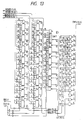
- Fig. 10 shows a hardware construction of the reduction processor 904.
- the data before conversion of 64 dots in the vertical direction is first written by the CPU four times every word and is respectively transferred to BOX0D (15:0), BOX1D (15:0), BOX2D (15:0), and BOX3D (15:0) and is sent to converters 910 to 913 for executing the data reduction in the vertical direction at reduction ratios of 1/2, 2/3, 4/5, and 7/8 as shown in Fig. 11, respectively.
- Outputs of the converters are transferred to a register REG of 16 bits and by reading the outputs Y0 to Y15 from the CPU, the reduced data can be obtained.
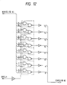
- Figs. 12 to 16 show internal circuit constructions of the converters 910 to 913.
- Fig. 12 shows the converter 910 to execute the 1/2 data reduction.
- Fig. 13 shows the converter 911 to perform the 2/3 data reduction.
- Fig. 14 shows the converter 912 to perform the 4/5 data reduction.
- Fig. 15 shows the converter 913 to perform the 7/8 data reduction.
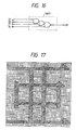
- Fig. 16 shows an internal structure of a UNIT in Figs. 13 to 15.
- ORCLX denotes a switch to select either one of the mode to simply thin out the bits and the mode to get the OR between the dot and the adjacent dot.
- CS(2:0) denotes an address decoding.
- CMP2(15,8), CMP3(15,0), CMP5(15,0), and CMP8(15,0) denote data after the conversion.
- the data when reducing, the data is formed by thinning out the dots.
- a reduced bit pattern can be also produced.
- Script characters superscript character, subscript character
- Script characters can be also formed by using such a circuit and processes of the software depending on the character kinds can be reduced.
- Fig. 17 shows an example (" " of a Chinese character, which reads "a") of a print font of (48 x 48 dots) by the recording apparatus of the embodiment 1.
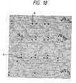
- Fig. 18 is a normalization font which is obtained by normalizing the print font of Fig. 17 by a prediction function.
- a hexadecimal notation in Fig. 19 shows a compressive font which is obtained by run length compressing the normalization font in Fig. 18 and the compressive font is stored in the ROM in such a format.
- the compressive font in Fig. 10 stored in the ROM is expanded to the normalization font in Fig. 18 by the run length expander and, after that, it is reconstructed to the original print font of Fig. 17 by the reverse prediction function, thereby obtaining the print data.
- the white word counter to count the number of words (the number of white words) of the white bits from the number of white bits has been added in the run length expander in Figs. 6-1 to 6-3, a length of continuous white words can be read by the CPU. Therefore, in the case where the white word appears, the hardware of the run length expander reduces a waiting time of the CPU corresponding to the time which is required for bit shift. A processing speed of the run length expanding process of the normalization font in which the white words exist is raised. The throughput of the whole recording apparatus can be improved.
- a block diagram of the run length expander according to the embodiment is almost similar to that shown in Figs. 6-1 to 6-3 except that only the white word counter differs. Therefore, a different point will now mainly be explained.
- the other constructions are similar to those in the embodiments 1 and 2.
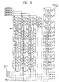
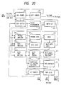
- Fig. 20 shows a circuit construction of the run length expander according to the embodiment.
- a constructing portion shown by reference numerals 200 to 216 shows a functional block similar to that in Figs. 6-1 to 6-3, its description is omitted here.
- the compressive data is shown and the normalization font one-word end flag FLG-NORM from the bit counter 215 and the compressive font one-word end flag FLG-COMP from the shift counter 201 are also shown as information which is read by the CPU.
- Reference numeral 230 denotes a white word counter as a functional block added in the embodiment.
- the white word counter 230 transfers the number of white bits to the white data bit pattern developer 212 as it is and generates "0" as the number of white words to be read by the CPU.
- the number of white bits is equal to or larger than the number of remaining bits, the number of remaining bits is transferred to the white data bit pattern developer 212.
- the quotient (upper bits of bit 4 or more in the binary notation) which is obtained by dividing the number that is derived by subtracting the number of remaining bits from the number of white bits by 16 is generated as the number of white words to be read by the CPU. At the same time, the remainder is latched and held for one word to be produced next. The remainder is transferred to the white data bit pattern developer after the normalization font which is formed was read by the CPU.
- the compressive font one-word end flag and the normalization font one-word completion flag are monitored.
- the compressive font one-word end flag is set, the compressive fonts of one word are written.
- the normalization font one-word completion flag is set, one word of the normalization fonts and the number of white words are read and the normalization fonts are transferred into the RAM.
- the processing routine is returned to the monitor of the flag.
- the data S0000 indicative of the words comprising only the white bits
- the white word counter 230 compares the number (namely, 357) of white bits and the number (15 in this case) of remaining bits. Since the number of white bits is equal or larger than the number of remaining bits in this case, the number of bits (15) is transferred to the white data bit pattern developer 212, thereby completing one word of the normalization font during the formation.
- the remainder "6" is latched and held for the next normalization font.
- the CPU detects that the normalization font one-word completion flag has been set, reads the normalization font, and transfers to the RAM. After that, the CPU reads the number of white words and transfers the data S0000 by the number of times corresponding to such a quotient value, namely, 21 times. Therefore, the CPU doesn't need to wait until the white word is formed 21 times. A processing speed of the run length expansion is improved.
- the run length expander clears the normalization font one-word completion flag and simultaneously transfers the number (6) of white bits which has been latched for the next word of the normalization font to the white bit pattern developer. The processing routine advances to the formation of the next word.
- the CPU accesses on a word (16 bits) unit basis, in case of accessing on a byte (8 bits) unit basis or a long word (32 bits) unit basis, by respectively setting the count values of the data reader 200 and latch circuit 216 and the shift counter 201 and bit counter 215 to 8 bits and 32 bits, the run length expander can be used.
- the processing speed of the run length expansion of the normalization fonts in the case where the words (white words) comprising only the white bits can be raised and the throughput of the whole recording apparatus can be improved.
- the processing speed of the data formation is raised and the throughput of the whole apparatus can be improved.
- the image data can be also displayed on a display apparatus such as CRT, liquid crystal display apparatus, or the like.
- the invention can be applied to a system which is constructed by a plurality of apparatuses or can be also applied to an apparatus comprising one apparatus. It will be obviously understood that the present invention can be also applied to the case where the invention is accomplished by supplying programs to a system or apparatus.
Abstract
Description
- The invention relates to output apparatus and method for outputting a character by using a run-length compressed font. The invention also relates to output apparatus and method having reduction of output data.
- (1) Hitherto, in a recording apparatus, image data such as font data or the like is stored into a recording section (ROM) in the recording apparatus and a character bit pattern corresponding to input data is accessed by the recording section and is developed as print data and is printed. In recent years, as for the image data such as font data or the like, print data of a higher resolution is required in order to raise a character quality. That is, the number of dots constructing one character of the font data increases in proportion to the resolution, the font which is formed by a matrix of (48 dots x 48 dots) needs 288 bytes (2306 bits) per font. In case of Japanese fonts, now assuming that about 7000 characters exist in one type style, a capacity of the ROM of the memory section of about two Mbytes is necessary. Hitherto, a method of compressing image data and storing into the recording apparatus is used to reduce the ROM capacity. For example, there is a run length compression.
- (2) Hitherto, in the recording apparatus, in case of printing with a width wider than a width of paper in the printing using the paper having a predetermined width, or in case of printing a continuous sheet in accordance with the size of cut paper, such a printing is realized by a form reduction. Specifically speaking, in the case where the image data corresponding to two pages of the continuous sheet having the size of (15 inches x 11 inches) is printed on a paper of the A4 size which is long in the vertical direction, the form is reduced into 1/2. In the case where the image data corresponding to one page of the continuous sheet of the size of (15 inches x 11 inches) is printed on a paper of the A4 size which is long in the lateral direction, the form is reduced into 2/3. In the case where the image data corresponding to one page of a paper of the B4 size which is long in the lateral direction is printed onto a paper of the A4 size which is long in the lateral direction, the form is reduced into 4/5. In the case where the image data corresponding to one page of a paper of the B4 size which is long in the vertical direction is printed onto a paper of the A4 size which is long in the vertical direction, the form is reduced into 7/8. In this manner, even in case of the recording apparatus which is designed so as to print on a cut sheet of the A4 size, the recorder can cope with the paper of a width wider than the A4 size.
- The above conventional apparatus (1) has the following drawbacks.
- 1. When a character font is not compressed but is stored as it is into the recording apparatus, the ROM capacity of the recording section is extremely large, resulting in an remarkable increase in costs.
- 2. In case of data compressing a character font by using the compressing method by the run length, a compression efficiency cannot be fairly raised.
- 3. In case of compressing a character font and storing into the memory section of the recording apparatus, since a logic to expand the compressive data is complicated and the processes must be executed on a bit unit basis, a load on a software of the expanding process is fairly large and an adverse influence is exerted on a throughput as a whole recording apparatus, resulting in a reduction in printing speed.
- The above conventional apparatus (2) has the following drawbacks.
- 1. In case of developing a character font and reducing a form after the image data of one line was developed, the reduction in the vertical direction must be executed on a bit unit basis, a load on the software of the reducing process is very large and an adverse influence is exerted on a throughput as a whole recording apparatus, resulting in a decrease in printing speed.
- 2. A software needs to be individually designed in dependence on a difference of reduction ratio, so that a time which is required to design remarkably increases.
- In a first aspect, the present invention provides a recording apparatus in which when image data is compressed and stored into the recording apparatus, in case of using the run length compression as such a compressing method, a prediction function process is executed to original font data, the data is converted so that white dots continue as long as possible, a compression ratio by the run length compression is raised, an ROM capacity of a recording section is remarkably reduced, and further a decoding process of the image data is realized by a hardware, thereby raising a processing speed of formation of font data and printing without reducing a throughput.
- Another aspect of the invention provides recording apparatus in which image data is compressed and stored into the recording apparatus, a run length compression is used as a compressing method, further an expansion of data is realized by a hardware, and image data is formed and recorded.
- Still another aspect of the invention aims to provide a recording apparatus in which a reduction in the vertical direction is performed by a simple hardware and form reduction data is formed and recorded.
- Further another aspect of the invention aims to provide a recording apparatus in which by improving a hardware for a run length expanding process, a print font can be formed at a high speed, and a higher printing speed is obtained.
- In a particular embodiment of the invention, there is provided a recording apparatus for developing character data from the outside to an internal font and recording as image data, wherein the apparatus comprises: memory means for storing the data; means for converting the character data from the outside into the internal font data; means for converting the data by a prediction function when the font data obtained by the above conversion is compressed and stored into the memory means; and means for run length expanding the compressive data stored in the memory means and for subsequently executing a reverse prediction function process and converting into desired image data.
- In a further embodiment, there is provided a recording apparatus for developing character data from the outside into internal font and printing as image data, wherein the apparatus comprises: memory means for storing the data; means for converting the character data from the outside into the internal font data; means for compressing the font data obtained by such a conversion and storing into the memory means; and means for run-length expanding the compressive data stored in the memory means, thereby converting into desired image data.
- In a further embodiment there is provided a recording apparatus for receiving print data from the outside and printing, wherein the apparatus has means for executing a bit operation to reduce in the vertical direction to the print data when executing a format reduction printing, thereby converting the print data into desired image data.
- In a further embodiment there is provided a recording apparatus for executing a run length compressing process and a run length expanding process when a character code which is sent from an external apparatus such as a host computer or the like is converted into a print font, wherein the apparatus has a white word counter for obtaining the number of words of only white dots from the number of white dots which was decided in the run length expanding process.
-
- Fig. 1 is an electric block diagram of a recording apparatus regarding one embodiment of the present invention;
- Fig. 2 is a block diagram of a run length expander in the embodiment;
- Fig. 3 is a block diagram of another run length expander;
- Fig. 4 is a diagram showing a run length code table according to a run length compressing method in the embodiment;
- Fig. 5 is an electric block diagram of a recording apparatus according to another embodiment of the invention;
- Figs. 6-1 to 6-3 are diagrams showing combination situations of data and a prediction function value table according to the embodiment;
- Figs. 7-1 and 7-2(1) to 7-2(18) are diagrams showing reconstructing situations of data according to a reverse prediction function process in the embodiment;
- Fig. 8 is a diagram showing a construction of a reverse prediction processor of the embodiment;
- Fig. 9 is an electric block diagram of a recording apparatus according to still another embodiment of the invention;
- Fig. 10 is a block diagram of a reduction processor in the embodiment;
- Figs. 11-1 to 11-4 are diagrams for explaining reduction bit converting methods;
- Fig. 12 is a block diagram of a 1/2 reduction converter;
- Fig. 13 is a block diagram of a 2/3 reduction converter;
- Fig. 14 is a block diagram of a 4/5 reduction converter;
- Fig. 15 is a block diagram of a 7/8 reduction converter;
- Fig. 16 is a block diagram of UNIT;
- Fig. 17 is a diagram showing an example of a print font of (48 x 48) dots;
- Fig. 18 is a diagram showing an example of a normalization font;
- Fig. 19 is a diagram showing an example of a compression font; and
- Fig. 20 is a block diagram showing a circuit construction of a run length expander according to an
embodiment 4 of the present invention. - Embodiments of the present invention will be described in detail hereinbelow with reference to the drawings.
- In case of specified data such as font data, it can be said that all of the data have regularity when considering of a broad visual field. When an attention is paid to one font, in case of a two-way code, 2n+1 states exist as the number of combinations of the past (n) pixels for one pixel (dot). However, it is actually impossible to provide such a logic to all of the states. Therefore, an attention is paid to only the pixels around one pixel. Particularly, in case of the font data, as compared with the general image data, the number of change points from the black dot to the white dot and from the white dot to the black dot is small. Therefore, there is considered a method whereby by expressing the change point by the black dot, an amount of white data section is increased and an efficiency of the run length compression is raised. On the other hand, although transition probabilities from the white dot to the white dot and from the black dot to the black dot are very high, transition probabilities from the white dot to the black dot and from the black dot to the white dot are very low. Therefore, binary states of the pixels adjacent to one pixel can be predicted. By applying the above principle to the original font data, the data is deformed to a form which is advantageous to the run length compression by using the prediction function.
- Since a black data group and a white data group certainly alternately appear in binary data such as font data, each group is expressed by a run length code. The fonts are sequentially searched from the head in the vertical direction and the continuous white dots are compressed by using a run length code (Fig. 4). When the search point reaches the lower edge of the font, the head dot of one right column is regarded to be continuous to the lower edge, so that it is one-dimensionally encoded. As for the run length code, the encoding is executed by a combination of "0" of continuous 0 to 22 bits (referred to as an operand) prior to "1" and a subsequent specific bit train (referred to as data) (which is decided by a length of operand). That is, now assuming that the number of continuous bits of "0" (= operand section) prior to "1" is equal to (n), the numerical value obtained from a predetermined data length table is set to a bit length of the subsequent "data section". The value which is obtained by adding an entry of a "data initial value table" corresponding to (n) to the value (referred to as "α") of the data section of m bits subsequent to "1" indicates the number of continuous white dots (white block). Although the white block and the black block certainly alternately appear, since whether the head block of the font is the white block or the black block must be judged, it is assumed that a data "identifier" of one bit indicating whether the head block is the white block or the black block is stored into the head of the compressed data. The font data which was run length compressed as mentioned above is stored into the memory section. When developing to a print pattern in accordance with input data from the host computer, a run length expanding process is executed by a hardware.
- Fig. 1 is an electric block diagram showing a construction of a control system of the recording apparatus according to the embodiment. In Fig. 1,
reference numeral 101 denotes a CPU for executing the operation and processes in the recording apparatus; 102 an ROM for storing control programs of theCPU 101, run length compressive data for production of fonts, and various kinds of data for processes; 103 an RAM to temporarily store image data to be printed by a recording head on the basis of the print data which is sent from the host computer and various kinds of data; 100 a data receiver for performing a communication control between the data receiver and an external apparatus such as a host computer or the like and for receiving the print data which is sent from the host computer; 105 a head driver for supplying a control signal from theCPU 101 to a head driver in order to record an image onto a recording medium by the recording apparatus and for transferring the image data to the recording head and for printing; and 106 a CR driver for a carriage motor driver and a carriage motor. - An
LF driver 107 of a paper feed motor driver and a paper feed motor is a control system for supplying a control signal to each driver from theCPU 101 and promoting the movements in the horizontal and vertical directions of the recording head which are necessary when the printing is executed to the recording medium.Reference numeral 104 denotes a run length expander for reoonstructing the run length compressive fonts stored in theROM 102 into a print bit pattern. - A control procedure in the embodiment will now be similarly described with reference to Fig. 1. First, the data received by the
data receiver 100 is temporarily stored in theRAM 103. A command, image data, and a character code are analyzed by theCPU 101 in accordance with the program stored in theROM 102. In case of the charaoter code, the font data which has previously been run length compressed and stored is read out from theROM 102 and sent to therun length expander 104. In the run length expander, bits of the font are produced and are sequentially stored into theRAM 103. At a time point when the development of the image data of one line is finished or when a print command is input from a host computer of the external apparatus, theCR driver 106 is driven and the print data is transferred from theRAM 103 to thehead driver 105 and is printed. After completion of the printing, theLF driver 107 is driven and a series of sequence is finished. - A block diagram of the
run length expander 104 in Fig. 2 will now be described in detail. An example of Fig. 2 shows the case where an access unit of the CPU is set to one word (16 bits) and a compressive font which was compressed in the vertical direction is expanded. A request for the run length expansion is generated from the CPU by a control flag FLG-CTRL. Compressive fonts which have previously been formed in accordance with a run length code table in Fig. 7-1 and Figs. 7-2(1) to 7-2(18) are transferred by an amount of one word to adata reader 200. When the data transfer is confirmed, the data is sequentially shifted one bit by one by adata shifter 202.Reference numeral 201 denotes a shift counter to count the number of shifting times. When it is detected that the shifting process is performed by only the number of bits of the compressive font and that the shifting process is finished, a compressive font one-word end flag FLG-COMP is set. The compressive font one-word end flag is cleared at a time point when the next compressive fonts of one word are transferred. First, the first bit of the first data is sent to aheader discriminator 203, by which a check is made to see if the subsequent bit is a white bit or a black bit. Information indicative of the result of the discrimination is sent to aswitch circuit 204 of an operand, data, and black data.Reference numeral 205 denotes an operand analyzer of white data for counting the number of bits "0" which were shifted by thedata shifter 202 and for obtaining the data initial value corresponding to a length of operand by the count value at the time point when "1" is detected and for transferring the data initial value to alatch circuit 206. Theoperand analyzer 205 obtains a bit length of the data section which has been set by each operand length and transfers information indicative of the bit length to adata analyzer 208. An end of operand analysis by theoperand analyzer 205 is informed to theswitch circuit 204. The data analyzer 208 is activated by theswitch circuit 204. The data analyzer 208 detects the bits "1" and "0" of the shift data subsequent to the operand and obtains the value shown in a data expressible range in Fig. 7-1 and Figs. 7-2(1) to 7-2(18) and transfers to adata latch circuit 209. - The end of data analysis by the
data analyzer 208 is subsequently informed to theswitch circuit 204. The values latched in thelatch circuits adder 207 and are added. The addition result is sent to alatch circuit 210 as the number of white data bits. The data shifting process of thedata shifter 202 is now once interrupted and a font developing process of the white data is started. For example, now assuming that the data of the operand section and data section is set to "000010100" (LSB ← → MSB), the operand section is set to "0001". As will be understood from Fig. 4, the data initial value at this time is equal to "49" and the bit length of the data section is equal to four bits. The processes until now are executed by theoperand analyzer 205. - Since the data section is "0100" (LSB ← →MSB), the value is equal to "2". This analysis is executed by the
data analyzer 208. After addition, the white data bit length is equal to "51". The white data bit number which was latched in thelatch circuit 210 is sequentially developed into a vertical bit train by a white databit pattern developer 212. A font matrix is formed by afont generator 214. The font which was formed into 16 bits in the vertical direction is transferred to alatch circuit 216 and its information is supplied to the CPU as a control signal (normalization font one-word completion flag FLG-NORM) and the font data is stored into the RAM. - A bit counter 215 counts the number of development bits, judges the end, informs the end to the
data shifter 202, allows the shifting process to be restarted, and activates ablack data analyzer 211. Theblack data analyzer 211 detects "1" or "0" of the bits which were shifted from thedata shifter 202 and sets the bits of only [(the number of bits "0") + 1] to black bits and activates a black databit pattern developer 213. After that, a font matrix is formed by processes similar to those in the white dot development. For example, in the case where four black dots continue, they are expressed as an operand and the data subsequent to them is expressed as "0001". - The above processes are executed by the number of times as many as only the number of bits of the shift data by the
shift counter 201. When the completion of the shifting process is detected, the process to read the compressive data from the ROM is again continued. The above processes are repeated until the normalization fonts of one character are formed. A judgment about the end is performed by counting the number of words of the print font by the CPU. - In the
embodiment 1, at a time point when the development of 16 bits in the vertical direction is finished, the control signal (normalization font one-word completion flag) is transmitted to the CPU. The CPU reads out the developed bit fonts by the control signal and stores into the RAM. However, in a run length expander as shown in Fig. 3, aDMA controller 220 is provided in place of thedata reader 200. After completion of the development of 16 bits in the vertical direction, the bit font is transferred to the RAM (DMA transfer) without transmitting through the CPU. The end of development of one character is judged by a transfer-end discriminator 217 for counting the data of one character, thereby stopping the activation of the DMA control. The stop of the DMA control is confirmed and the end of the development of one character can be informed to the CPU by a flag. Due to this, a processing speed can be further raised. In the case where a plurality of font sizes exit, acharacter size setter 218 having a switch is provided and a data counter of one character in the transfer-end discriminator 217 is made variable, thereby also making the apparatus effective to fonts of different sizes. Further, in case of registering external characters such as down-load characters or the like from the host computer, by storing the run length compressing process as a program into the internal RAM, an external character registering area can be extremely reduced to a size smaller than the ordinary registering area. Such a construction can also contribute to the reduction of the RAM capacity. - According to the
embodiment 1 as described above, an information amount of the font data in the recording apparatus can be decreased and the costs can be reduced. Further, by executing the expanding process of the run length compressed data by a hardware, a processing speed to make the font data can be raised, the load of the software can be fairly reduced, and the throughput of the whole recording apparatus can be improved. - Fig. 5 is an electric block diagram showing a construction of a control system of a recording apparatus according to an
embodiment 2.Reference numerals 100 to 107 denote the same component elements as those shown in Fig. 1 and theembodiment 2 is similar to theembodiment 1 except that areverse prediction processor 108 exists. - In Fig. 5,
reference numeral 101 denotes the CPU for executing the operation and processes in the recording apparatus; 102 the ROM to store the control programs for theCPU 101, run length compressive data to form fonts, and various kinds of data for processes; 103 the RAM to temporarily store the image data and various kinds of data to be printed by a recording head based on the print data which is sent from the host computer; 100 the data receiver for executing a communication control between the data receiver and an external apparatus such as a host computer or the like and for fetching the print data which is sent from the host computer; 105 the head driver to which the control signal is supplied from theCPU 101 in order to record an image onto a recording medium by the recording apparatus and which transfers image data to the recording head and prints; and 106 the CR driver for a carriage motor driver and a carriage motor. - The
LF driver 107 of the paper feed motor driver and the paper feed motor is a control system for supplying a control signal from theCPU 101 to each driver and for promoting the movement in the horizontal direction and the movement in the vertical direction of the recording head which are necessary when printing onto a recording medium.Reference numeral 104 denotes the run length expander for reconstructing a print bit pattern from the run length compressive font stored in theROM 102.Reference numeral 108 denotes the reverse prediction processor for reconstructing the original font from the data which was expanded by therun length expander 104. - A control procedure in the embodiment will now be described with reference to Fig. 5 in a manner similar to that mentioned above. First, the data which was received by the
data receiver 100 is once stored into theRAM 103 and a command, image data, and a character code are analyzed by theCPU 101 in accordance with the program stored in theROM 102. In case of the character code, the font data which has previously been data converted by the prediction function as mentioned above and has been run length compressed and stored is read out from theROM 102 and is sent to therun length expander 104. The bits of the font are produced by the run length expander and are sequentially stored into theRAM 103. The stored data is sent to thereverse prediction processor 108 and a print font pattern is formed. At a time point when the development of the image data of one line is finished or when a print command is input from the host computer as an external apparatus, theCR driver 106 is driven. The print data is transferred from theRAM 103 to thehead driver 105 and is printed. After completion of the printing, theLF driver 107 is driven and a series of operation sequence is finished. - Explanation will now be made in accordance with a prediction function value table in Fig. 6-1.
- In case of paying an attention to the dots which are locating at the upper position (b), left position (c), and oblique position (a) of one dot (d) existing in a font shown in Fig. 6-2, a dot in which a probability at which the dot appears as (d) is high for a combination of the three dots (a, b, c) is called a prediction function. The value of the prediction function for the dots (a to c) is compared with the value of the actual bit (d). When they coincide, the value of (d) is replaced to "0" (white). When they differ, (d) is replaced to "1" (black). Namely, a pattern of a high transition probability is replaced by white. Due to this, the dots in most of the portions are replaced by white and a compression efficiency of the run length compression is raised.
- Matrices shown in Fig. 6-3 are expressed by the following prediction function equation.

- As mentioned above, the original font data is converted by the prediction function, the converted data is run length compressed, and the compressive data is stored into the memory of the recording apparatus. When the character data which is sent from the external apparatus such as a host computer or the like is developed into a character font, the run length expansion is first executed from the compressive data stored in the memory and a logic circuit of the reverse prediction function process is assembled for the data which was run length expanded.
- The logical equation of a reverse prediction function of the reconstructing process is as follows (refer to Fig. 7-1).

Y = output data
D = unprocessed data - Figs. 7-2(1) to 7-2(18) show examples of the reconstructing process.
- Fig. 7-2(1) relates to the data which was formed by performing the prediction function process to the original font data. The data is sequentially reconstructed in accordance-with the equation (2) from the dot existing at the left upper edge of the above data. In Figs. 7-2(2)to 7-2(17), one dot on the outer periphery at the left and upper edges is virtually regarded as white (0). Among the four dots surrounded by a bold frame, three dots locating at the upper position "B", left position "C", and oblique position "A" of the relevant dot "D" are taken out. The value of the dot "D" is checked. If D = "0", this means that the value of D coincides with the prediction function value. If D = "1", this means that the value of D differs from the prediction function value.
- When considering in the matrix of Fig. 7-2(2), with respect to four dots surrounded by a bold frame, the dot corresponding to "D" is set to black "1" and differs from the prediction function value. Therefore, from the prediction function value table of Fig. 2, it will be understood that the dot is set to black "1". The process in Fig. 7-2(3) will now be executed. In this instance, the dot produced in Fig. 7-2(2) is used as a dot existing at the right upper position. In a manner similar to Fig. 7-2(2), when an attention is paid to the dot "D", it is equal to white "0" and coincides with the prediction function value. In this case, it will be understood from the prediction function value table of Fig. 2 that the matrix of Fig. 7-2(3) corresponds to the pattern of "3" and the dot is equal to black "1". By sequentially repeating the above processes, a pattern of Fig. 7-2(18) is reconstructed. A logic which satisfies the above logic equation is constructed every bit by the hardware and a desired character font data formation is realized.
- Fig. 8 is a diagram showing a hardware construction of the
reverse prediction processor 108. In the above logic, the converting operation is executed every 16 bits. The converted data of the previous line is transferred to AB15 to AB0 and the unconverted data is transferred to D15 to D0. The reverse prediction function processing logic operates simultaneously with the completion of the data transfer and the data corresponding to those bits is output to Y15 to Y0. By reading out the outputs Y15 to Y0, the data to which the reverse prediction function process was performed can be obtained. The least significant bit is latched for the process of the most significant bit of the next dot train. After completion of the reading operation, the input section is cleared. - Although the reverse prediction function process has been executed every 16 bits in the above embodiment, by installing logic circuits of the number corresponding to one dot train in the vertical direction of the font size for each bit, there is no need to clear the input section by the software. A processing speed can be raised and the data which was converted without transmitting through the CPU can be also transferred to the RAM. In case of registering an external character such as a down-load character or the like from the host computer, by storing the run length compressing process and the prediction function process as programs of the internal ROM, the external character registration area can be remarkably reduced to an area smaller than the ordinary registration area. The invention can also contribute to the decrease in RAM capacity.
- According to the
embodiment 2 as described above, by converting the original font data by using the prediction function, most of the portions of the black dots can be replaced to the white dots, and the compression efficiency of the run length compression can be extremely raised. By executing the reverse prediction function process by the hardware, the load of the CPU (software) can be reduced, the processing speed of the font data formation can be raised, and the throughput of the whole recording apparatus can be improved. - In case of reducing data in the vertical direction, the dots at predetermined positions in the data before reduction are thinned out by each reduction ratio (Figs. 11-1 to 11-4). In Fig. 11-1, the data is thinned out every other dot by the 1/2 reduction ratio. In Fig. 11-2, the data is thinned out at a 2/3 reduction ratio of one dot per three dots. In Fig. 11-3 , the data is thinned out at a 4/5 reduction ratio of one dot per five dots. In Fig. 11-4, the data is thinned out at a 7/8 reduction ratio of one dot per eight dots. A logic is constructed so that the data can be converted as shown in Figs. 11-1 to 11-4, thereby realizing a high processing speed.
- Fig. 9 is an electric block diagram showing a construction of a control system of a recording apparatus according to the embodiment. In Fig. 9,
reference numeral 901 denotes a CPU for executing the operation and processes in the recording apparatus; 902 an ROM for storing control programs for theCPU 901 and character fonts; 903 an RAM for temporarily storing image data and various kinds of data to be printed by a print head based on the print data which is sent from a host computer; 900 a data receiver for executing a communication control between the data receiver and an external apparatus such as a host computer or the like and for taking the print data which is sent from the host computer; 905 a head driver for supplying a control signal from theCPU 901 to the head driver in order to record an image onto a recording medium by the recording apparatus and for transferring image data to the recording head and printing; and 906 a CR driver of a carriage motor driver and a carriage motor. AnLF driver 907 of a paper feed motor driver and a paper feed motor is a control system for supplying a control signal to each driver from theCPU 901 and for promoting a movement in the horizontal direction and a movement in the vertical direction of the recording head which are necessary for printing.Reference numeral 904 denotes a reduction processor for performing a bit conversion in the vertical direction in accordance with a reduction ratio which was set by theCPU 901. - A control procedure in the invention will now be described with reference to Fig. 9 in a manner similar to that mentioned above. First, the data which was received by the
data receiver 900 is once stored into theRAM 903 and a command, image data, and a character code are analyzed by theCPU 901 in accordance with the program stored in theROM 902. In case of the character code, the font data which has previously been stored in theROM 902 is sequentially read out and a bit pattern is stored into theRAM 903. The stored bit pattern is sent to thereduction processor 904 in accordance with a reduction ratio of the format reduction which was set by the CPU. Each desired bit pattern is formed and is again stored into theRAM 903. At a time point when the development of the image data of one line is finished or when a print command is input from the host computer as an external apparatus, theCR driver 906 is driven and the print data is transferred from theRAM 903 to thehead driver 905 and is printed. When the data is transferred to thehead driver 905, the data is also simultaneously reduced in the lateral direction. The data reduction in the lateral direction is executed by a method of thinning out the data on a byte unit basis or on a word unit basis. After completion of the printing, theLF driver 907 is driven and a series of operation sequence is finished. - Fig. 10 shows a hardware construction of the
reduction processor 904. In the above logic, the data before conversion of 64 dots in the vertical direction is first written by the CPU four times every word and is respectively transferred to
BOX0D (15:0), BOX1D (15:0), BOX2D (15:0), and BOX3D (15:0)
and is sent to converters 910 to 913 for executing the data reduction in the vertical direction at reduction ratios of 1/2, 2/3, 4/5, and 7/8 as shown in Fig. 11, respectively. Outputs of the converters are transferred to a register REG of 16 bits and by reading the outputs Y0 to Y15 from the CPU, the reduced data can be obtained. - Figs. 12 to 16 show internal circuit constructions of the converters 910 to 913. Fig. 12 shows the converter 910 to execute the 1/2 data reduction. Fig. 13 shows the converter 911 to perform the 2/3 data reduction. Fig. 14 shows the converter 912 to perform the 4/5 data reduction. Fig. 15 shows the converter 913 to perform the 7/8 data reduction. Fig. 16 shows an internal structure of a UNIT in Figs. 13 to 15. In the diagrams, ORCLX denotes a switch to select either one of the mode to simply thin out the bits and the mode to get the OR between the dot and the adjacent dot. CS(2:0) denotes an address decoding. When the reduced data is read by the CPU, it is read four times by the value of CS on a word unit basis. CMP2(15,8), CMP3(15,0), CMP5(15,0), and CMP8(15,0) denote data after the conversion.
- In the
embodiment 3, when reducing, the data is formed by thinning out the dots. However, in the case where the quality of the produced data becomes a problem, by providing a switch to select either one of the mode to get the OR between the data to be thinned out and the adjacent data and the mode to simply thin out and by assembling such a circuit into the apparatus, a reduced bit pattern can be also produced. Script characters (superscript character, subscript character) can be also formed by using such a circuit and processes of the software depending on the character kinds can be reduced. - According to the
embodiment 3 as described above, when a format reduction is executed, by realizing the bit conversion of the vertical reduction by a hardware, the load of the software can be reduced, the processing speed of the data formation can be raised, and the throughput of the whole recording apparatus can be improved. - Fig. 17 shows an example ("" of a Chinese character, which reads "a") of a print font of (48 x 48 dots) by the recording apparatus of the

embodiment 1. Fig. 18 is a normalization font which is obtained by normalizing the print font of Fig. 17 by a prediction function. A hexadecimal notation in Fig. 19 shows a compressive font which is obtained by run length compressing the normalization font in Fig. 18 and the compressive font is stored in the ROM in such a format. In the recording apparatus, the compressive font in Fig. 10 stored in the ROM is expanded to the normalization font in Fig. 18 by the run length expander and, after that, it is reconstructed to the original print font of Fig. 17 by the reverse prediction function, thereby obtaining the print data. - When the compressive font stored in the ROM in the format of Fig. 19 is expanded to the normalization font in Fig. 18 by using the run length expander in Fig. 6, when a reduction ratio of the black bits by the prediction function is high, a length of continuous white bits becomes long, so that a portion in which white bits continue appears over a plurality of words. When considering a portion from the black bit at a point A to the black bit at a point B in Fig. 18 as an example, 357 white bits continue. When they are divided on a word unit basis, 21 words become the words comprising only white bits, namely, white words (words of data S0000). In case of Fig. 18, the number of white words is equal to 103, which is almost similar to 3/4 of the number (144) of all words.
- In the run length expander in Figs. 6-1 to 6-3, even in such a case where the white words continue, one word of the normalization font is formed while shifting one bit by one. Therefore, until one word is completed, the CPU doesn't detect that the word is a white word. In case of the normalization font in which many white words exist, consequently, it takes a long time for the run length expansion.
- In the embodiment, since the white word counter to count the number of words (the number of white words) of the white bits from the number of white bits has been added in the run length expander in Figs. 6-1 to 6-3, a length of continuous white words can be read by the CPU. Therefore, in the case where the white word appears, the hardware of the run length expander reduces a waiting time of the CPU corresponding to the time which is required for bit shift. A processing speed of the run length expanding process of the normalization font in which the white words exist is raised. The throughput of the whole recording apparatus can be improved.
- A block diagram of the run length expander according to the embodiment is almost similar to that shown in Figs. 6-1 to 6-3 except that only the white word counter differs. Therefore, a different point will now mainly be explained. The other constructions are similar to those in the
embodiments - Fig. 20 shows a circuit construction of the run length expander according to the embodiment.
- In Fig. 20, since a constructing portion shown by
reference numerals 200 to 216 shows a functional block similar to that in Figs. 6-1 to 6-3, its description is omitted here. In Fig. 20, however, in addition to a request (control flag) for the run length expansion which is written by the CPU, although not shown in Figs. 6-1 to 6-3, the compressive data is shown and the normalization font one-word end flag FLG-NORM from thebit counter 215 and the compressive font one-word end flag FLG-COMP from theshift counter 201 are also shown as information which is read by the CPU.Reference numeral 230 denotes a white word counter as a functional block added in the embodiment. When the number of white bits which is derived from the whitedata latch circuit 210 is smaller than the number of remaining bits of one word during the formation in thebit counter 215, thewhite word counter 230 transfers the number of white bits to the white databit pattern developer 212 as it is and generates "0" as the number of white words to be read by the CPU. When the number of white bits is equal to or larger than the number of remaining bits, the number of remaining bits is transferred to the white databit pattern developer 212. The quotient (upper bits ofbit 4 or more in the binary notation) which is obtained by dividing the number that is derived by subtracting the number of remaining bits from the number of white bits by 16 is generated as the number of white words to be read by the CPU. At the same time, the remainder is latched and held for one word to be produced next. The remainder is transferred to the white data bit pattern developer after the normalization font which is formed was read by the CPU. - The operation of the CPU in the embodiment will now be described.
- After the run length expanding process was started by the control flag and the compressive font was written, the compressive font one-word end flag and the normalization font one-word completion flag are monitored. When the compressive font one-word end flag is set, the compressive fonts of one word are written. When the normalization font one-word completion flag is set, one word of the normalization fonts and the number of white words are read and the normalization fonts are transferred into the RAM. When the number of white words is equal to 0, the processing routine is returned to the monitor of the flag. When the number of white words is not equal to 0, the data S0000 (indicative of the words comprising only the white bits) of the number as many as only the number of white words is transferred to the RAM.
- The points A and B in Fig. 18 will now be described as examples. When it is known that the number of white bits is equal to 357, the
white word counter 230 compares the number (namely, 357) of white bits and the number (15 in this case) of remaining bits. Since the number of white bits is equal or larger than the number of remaining bits in this case, the number of bits (15) is transferred to the white databit pattern developer 212, thereby completing one word of the normalization font during the formation. The quotient (357 - 15 = 342; 342/16 = 21 and the remainder is equal to 6) which is obtained by dividing the number that is obtained by subtracting the number of remaining bits from the number of white bits by 16 is subsequently set to the number of white words. The remainder "6" is latched and held for the next normalization font. The CPU detects that the normalization font one-word completion flag has been set, reads the normalization font, and transfers to the RAM. After that, the CPU reads the number of white words and transfers the data S0000 by the number of times corresponding to such a quotient value, namely, 21 times. Therefore, the CPU doesn't need to wait until the white word is formed 21 times. A processing speed of the run length expansion is improved. When the normalization font is read, the run length expander clears the normalization font one-word completion flag and simultaneously transfers the number (6) of white bits which has been latched for the next word of the normalization font to the white bit pattern developer. The processing routine advances to the formation of the next word. - In the embodiment, although the CPU accesses on a word (16 bits) unit basis, in case of accessing on a byte (8 bits) unit basis or a long word (32 bits) unit basis, by respectively setting the count values of the
data reader 200 andlatch circuit 216 and theshift counter 201 and bit counter 215 to 8 bits and 32 bits, the run length expander can be used. - In addition to the above embodiment, the invention can be also applied to the following examples.
- 1) In the
embodiment 4, the CPU writes the compressive font into the run length expander and at a time point when the development of one word (16 bits) is finished, the normalization font one-word completion flag is detected and the produced normalization fonts are read out and stored in the RAM. On the other hand, by providing a DMA section for directly transferring the data to the RAM without transmitting through the CPU after completion of the development of one word, a data counter (for counting up to 144 words in case of 48 x 48 dots) of the data of one character, and a circuit for generating the data S0000 of the number as many as the number of white words, the judgment about the end of the development of one character can be also executed in the run length expander. Due to this, a processing speed can be further raised. - 2) Further, a circuit for setting a start address of the RAM in which the compressive font storage start addresses in the ROM of the number corresponding to one line have been stored and a start address of the RAM in which the normalization fonts after completion of the run length expanding process of the number corresponding to one line have been stored from the CPU is added to the DMA section, so that all of the run length expanding processes of one line can be executed by the hardware. Since the load of the CPU is remarkably reduced, the throughput of the whole recording apparatus can be further improved.
- 3) Further, by adding a circuit for transferring the data to the reverse prediction processor and converting into the print font at a time point when the data of one column (3 words = 48 bits in the embodiment 4) of the normalization fonts, all of the portions of the run length expansion and the conversion by the reverse prediction function in the operation sequence of the recording apparatus such as data reception, analysis of the character code, run length expansion, conversion by the reverse prediction function, and printing operation can be accomplished by the hardware. Therefore, the throughput of the whole recording apparatus is extremely raised.
- 4) Although the font size has been set to 48 x 48 dots in the
embodiment 4, in the case where a plurality of font sizes exist, by newly providing a selector to thereby enable the count values of theshift counter 201 and bit counter 215 to be variable, the run length expander can be also used for different font sizes. - As described above, according to the
embodiment 4, the processing speed of the run length expansion of the normalization fonts in the case where the words (white words) comprising only the white bits can be raised and the throughput of the whole recording apparatus can be improved. - According to the invention as described above, the processing speed of the data formation is raised and the throughput of the whole apparatus can be improved.
- Although the embodiments have been described by using the recording apparatus, the image data can be also displayed on a display apparatus such as CRT, liquid crystal display apparatus, or the like.
- The invention can be applied to a system which is constructed by a plurality of apparatuses or can be also applied to an apparatus comprising one apparatus. It will be obviously understood that the present invention can be also applied to the case where the invention is accomplished by supplying programs to a system or apparatus.
Claims (23)
- An output apparatus comprising:
memory means for storing compressed font data which has been obtained by converting dot font pattern data using a prediction function and run length compressing said converted dot pattern data;
expanding means for run length expanding the font data which corresponds to character data to be generated and which has been stored in said memory means; and
converting means for converting said expanded dot pattern data into image data by using a reverse prediction function. - An apparatus according to claim 1, wherein said expanding means is realized by a hardware.
- An apparatus according to claim 1, wherein said converting means is realized by a hardware.
- An apparatus according to claim 1, wherein a DMA transfer is used when the run length expansion is executed by said expanding means.
- An apparatus according to claim 4, wherein when said DMA transfer is executed, the end of data transfer of one character is judged on the basis of character size setting means.
- An apparatus according to claim 1, further comprising:
input means for inputting dot font pattern data corresponding to the character data;
converting means for converting said input dot font pattern data by using a prediction function;
compressing means for run-length compressing said converted dot pattern data; and
memory control means for storing said compressed font data into said memory means. - An apparatus according to claim 1, further comprising white word number counting means for counting the number of words of white dots on the basis of the number of white dots when the run length expansion is executed by said expanding means.
- An output method comprising:
a step of using memory means for storing compressed font data which has been obtained by converting dot font pattern data using a prediction function and run length compressing said converted dot pattern data;
an expanding step of run length expanding said font data which corresponds to character data to be generated and which has been stored in said memory means; and
a converting step of converting said expanded dot pattern data into image data by using a reverse prediction function. - A method according to claim 8, wherein said expanding step is realized by a hardware.
- A method according to claim 8, wherein said converting step is realized by a hardware.
- A method according to claim 8, wherein a DMA transfer is used when the run length expansion is executed in said expanding step.
- A method according to claim 11, wherein when said DMA transfer is executed, the end of data transfer of one character is judged on the basis of character size setting means.
- A method according to claim 8, further comprising:
an input step of inputting dot font pattern data corresponding to the character data;
a converting step of converting said input dot font pattern data by using a prediction function;
a compressing step of run length compressing said converted dot pattern data; and
a memory controls step of storing said compressed font data into said memory means. - A method according to claim 8, further comprising:
a white word number counting step of counting the number of words of white dots on the basis of the number of white dots when the run length expansion is executed in said expanding step. - An output apparatus comprising:
input means for inputting character data from an upper order apparatus;
producing means for producing dot pattern data corresponding to said character data;
reduction processing means for reducing the data by thinning out the dot pattern data when the dot pattern data is produced by said producing means: and
output means for outputting said reduced dot pattern data. - An apparatus according to claim 15, wherein said reducing process is realized by a hardware.
- An apparatus according to claim 15, further comprising reduction ratio designating means for designating a reduction ratio.
- An output method comprising:
an input step of inputting character data from an upper order apparatus;
a producing step of producing dot pattern data corresponding to said character data;
reduction processing step of reducing the data by thinning out the dot pattern data when the dot pattern data is produced in said producing step; and
an output step of outputting said reduced dot pattern data. - A method according to claim 18, wherein said reducing process is realized by a hardware.
- A method according to claim 18, further comprising a reduction ratio designating step of designating a reduction ratio.
- A character font output system wherein dot patterns are subjected to predictive coding prior to run length data compression.
- A memory device wherein compressed font data have been stored using a predictive function and run length compression, for use in an apparatus or method according to any of claims 1 to 14 and 20.
- An apparatus or method according to claim 17 or 20 wherein said reduction ratio designating step is performed automatically in response to designation of a paper size different to an actual output paper size.
Applications Claiming Priority (6)
| Application Number | Priority Date | Filing Date | Title |
|---|---|---|---|
| JP8836993 | 1993-04-15 | ||
| JP8836993 | 1993-04-15 | ||
| JP88369/93 | 1993-04-15 | ||
| JP28707993A JP3327650B2 (en) | 1993-04-15 | 1993-11-16 | Recording device |
| JP287079/93 | 1993-11-16 | ||
| JP28707993 | 1993-11-16 |
Publications (3)
| Publication Number | Publication Date |
|---|---|
| EP0629973A2 true EP0629973A2 (en) | 1994-12-21 |
| EP0629973A3 EP0629973A3 (en) | 1995-05-17 |
| EP0629973B1 EP0629973B1 (en) | 2000-07-12 |
Family
ID=26429762
Family Applications (1)
| Application Number | Title | Priority Date | Filing Date |
|---|---|---|---|
| EP94302656A Expired - Lifetime EP0629973B1 (en) | 1993-04-15 | 1994-04-14 | Output apparatus and method |
Country Status (9)
| Country | Link |
|---|---|
| US (1) | US5586225A (en) |
| EP (1) | EP0629973B1 (en) |
| JP (1) | JP3327650B2 (en) |
| KR (1) | KR0134750B1 (en) |
| CN (1) | CN1102257C (en) |
| AT (1) | ATE194721T1 (en) |
| DE (1) | DE69425194D1 (en) |
| HK (1) | HK1011779A1 (en) |
| TW (1) | TW344055B (en) |
Families Citing this family (10)
| Publication number | Priority date | Publication date | Assignee | Title |
|---|---|---|---|---|
| JP3160177B2 (en) * | 1995-03-06 | 2001-04-23 | 松下電器産業株式会社 | Facsimile electronic mail device |
| US6885470B1 (en) | 1995-03-06 | 2005-04-26 | Matsushita Electric Industrial Co., Ltd. | Electronic mail system |
| US6778287B1 (en) | 1995-03-06 | 2004-08-17 | Matsushita Electric Industrial Co., Ltd. | Electronic mail system |
| US5959656A (en) * | 1995-05-15 | 1999-09-28 | Korea Electronics Technology Institute | Method and apparatus for enhancing laser printer resolution by using a laser beam modulation technique |
| US5712675A (en) * | 1995-05-15 | 1998-01-27 | Chung-duck Kim | Method and apparatus for enhancing laser printer resolution |
| JP2001047670A (en) * | 1999-05-28 | 2001-02-20 | Canon Inc | Printing apparatus, method for resolution convert printing by printing apparatus, and memory medium with computer readable program recorded therein |
| US7111248B2 (en) * | 2002-01-15 | 2006-09-19 | Openwave Systems Inc. | Alphanumeric information input method |
| US8045219B2 (en) * | 2003-06-05 | 2011-10-25 | Stmicroelectronics, Inc. | Printed media products including data files provided in multiple layers of encoded, colored dots |
| JP2014012354A (en) * | 2012-07-04 | 2014-01-23 | Seiko Epson Corp | Data processor, recorder, data processing method and program |
| CN104812405A (en) | 2012-09-19 | 2015-07-29 | 国立大学法人大阪大学 | Pneumococcal vaccine containing pneumococcal surface protein a |
Citations (9)
| Publication number | Priority date | Publication date | Assignee | Title |
|---|---|---|---|---|
| GB2167585A (en) * | 1984-11-15 | 1986-05-29 | Toshiba Kk | Font compression method and apparatus |
| JPS6218169A (en) * | 1985-07-16 | 1987-01-27 | Sanyo Electric Co Ltd | Imaging device |
| GB2201273A (en) * | 1987-02-23 | 1988-08-24 | Oki Electric Ind Co Ltd | Printing mode control system |
| EP0434005A1 (en) * | 1989-12-19 | 1991-06-26 | Sharp Kabushiki Kaisha | Image data compression method using a run prediction technique |
| EP0448725A1 (en) * | 1989-10-17 | 1991-10-02 | Nakajima All Precision Co., Ltd. | Character data compression method and character modification method |
| EP0471482A2 (en) * | 1990-08-03 | 1992-02-19 | Canon Kabushiki Kaisha | Character processing method |
| EP0478304A2 (en) * | 1990-09-25 | 1992-04-01 | Brother Kogyo Kabushiki Kaisha | Character output device |
| EP0533049A2 (en) * | 1991-09-18 | 1993-03-24 | Seiko Epson Corporation | Printer for printing bold characters |
| EP0602818A1 (en) * | 1992-11-30 | 1994-06-22 | Canon Kabushiki Kaisha | Dot data compression and expansion method and apparatus |
Family Cites Families (5)
| Publication number | Priority date | Publication date | Assignee | Title |
|---|---|---|---|---|
| JPH0832469B2 (en) * | 1988-01-29 | 1996-03-29 | 富士通株式会社 | Horizontal expansion method of bitmap font |
| US5272768A (en) * | 1989-02-21 | 1993-12-21 | Hewlett-Packard Company | Blank strip font compression method and device, and resulting stored, decompressible font |
| JP2647226B2 (en) * | 1990-03-23 | 1997-08-27 | 沖電気工業株式会社 | Dot pattern compression method and decompression method |
| US5121468A (en) * | 1990-10-10 | 1992-06-09 | Fuji Xerox Co., Ltd. | Printer image control system |
| US5208676A (en) * | 1990-12-04 | 1993-05-04 | Fuji Xerox Co., Ltd. | Image processing apparatus with data storage region management, memory space allocation in accordance with detected compression ratio of data |
-
1993
- 1993-11-16 JP JP28707993A patent/JP3327650B2/en not_active Expired - Fee Related
-
1994
- 1994-01-14 KR KR1019940007790A patent/KR0134750B1/en not_active IP Right Cessation
- 1994-04-09 TW TW083103111A patent/TW344055B/en active
- 1994-04-13 US US08/226,844 patent/US5586225A/en not_active Expired - Fee Related
- 1994-04-14 DE DE69425194T patent/DE69425194D1/en not_active Expired - Lifetime
- 1994-04-14 EP EP94302656A patent/EP0629973B1/en not_active Expired - Lifetime
- 1994-04-14 AT AT94302656T patent/ATE194721T1/en not_active IP Right Cessation
- 1994-04-15 CN CN94105565.5A patent/CN1102257C/en not_active Expired - Fee Related
-
1998
- 1998-12-01 HK HK98112648A patent/HK1011779A1/en not_active IP Right Cessation
Patent Citations (9)
| Publication number | Priority date | Publication date | Assignee | Title |
|---|---|---|---|---|
| GB2167585A (en) * | 1984-11-15 | 1986-05-29 | Toshiba Kk | Font compression method and apparatus |
| JPS6218169A (en) * | 1985-07-16 | 1987-01-27 | Sanyo Electric Co Ltd | Imaging device |
| GB2201273A (en) * | 1987-02-23 | 1988-08-24 | Oki Electric Ind Co Ltd | Printing mode control system |
| EP0448725A1 (en) * | 1989-10-17 | 1991-10-02 | Nakajima All Precision Co., Ltd. | Character data compression method and character modification method |
| EP0434005A1 (en) * | 1989-12-19 | 1991-06-26 | Sharp Kabushiki Kaisha | Image data compression method using a run prediction technique |
| EP0471482A2 (en) * | 1990-08-03 | 1992-02-19 | Canon Kabushiki Kaisha | Character processing method |
| EP0478304A2 (en) * | 1990-09-25 | 1992-04-01 | Brother Kogyo Kabushiki Kaisha | Character output device |
| EP0533049A2 (en) * | 1991-09-18 | 1993-03-24 | Seiko Epson Corporation | Printer for printing bold characters |
| EP0602818A1 (en) * | 1992-11-30 | 1994-06-22 | Canon Kabushiki Kaisha | Dot data compression and expansion method and apparatus |
Non-Patent Citations (1)
| Title |
|---|
| PATENT ABSTRACTS OF JAPAN vol. 11, no. 190 (E-517) 18 June 1987 & JP-A-62 018 169 (SANYO ELECTRIC CO) * |
Also Published As
| Publication number | Publication date |
|---|---|
| ATE194721T1 (en) | 2000-07-15 |
| EP0629973B1 (en) | 2000-07-12 |
| KR0134750B1 (en) | 1998-05-15 |
| TW344055B (en) | 1998-11-01 |
| CN1108399A (en) | 1995-09-13 |
| EP0629973A3 (en) | 1995-05-17 |
| JP3327650B2 (en) | 2002-09-24 |
| HK1011779A1 (en) | 1999-07-16 |
| DE69425194D1 (en) | 2000-08-17 |
| US5586225A (en) | 1996-12-17 |
| JPH06344601A (en) | 1994-12-20 |
| CN1102257C (en) | 2003-02-26 |
Similar Documents
| Publication | Publication Date | Title |
|---|---|---|
| US4881180A (en) | Character image generating circuit | |
| US6212234B1 (en) | Color image encoding apparatus and color image decoding apparatus | |
| JPH0863606A (en) | System and method for compression of graphic image | |
| US5768486A (en) | Printing apparatus | |
| JPH10147018A (en) | Printing device and memory control system | |
| EP0629973B1 (en) | Output apparatus and method | |
| US6135653A (en) | Data compression method and apparatus and data expansion method and apparatus | |
| US7103833B1 (en) | Image processing apparatus, output apparatus, image processing system and image processing method | |
| EP0357383B1 (en) | Output apparatus | |
| EP0398681A2 (en) | Output apparatus | |
| EP0424885B1 (en) | Control apparatus of high speed/high quality printer | |
| JP2815832B2 (en) | Page Printer Band Printing Method | |
| EP0675428B1 (en) | Printing system and method of printing graphic data | |
| JPH04230172A (en) | Facsimile data processor | |
| JPH11203070A (en) | Printer controller | |
| JP2972466B2 (en) | Dot pattern compression method and apparatus and output method and apparatus | |
| JP3160446B2 (en) | Recording device | |
| JP3663853B2 (en) | Image processing device | |
| US6281985B1 (en) | Print control apparatus, print control method, and memory medium | |
| JPH08331369A (en) | Image processing unit | |
| JP2872144B2 (en) | Printing equipment | |
| JP3657081B2 (en) | Printer controller | |
| JP2937508B2 (en) | Bitmap expansion method | |
| JP3428817B2 (en) | Print control device and method | |
| JPH11341290A (en) | Image generation system and method for performing encoding data compression |
Legal Events
| Date | Code | Title | Description |
|---|---|---|---|
| PUAI | Public reference made under article 153(3) epc to a published international application that has entered the european phase |
Free format text: ORIGINAL CODE: 0009012 |
|
| AK | Designated contracting states |
Kind code of ref document: A2 Designated state(s): AT BE CH DE DK ES FR GB GR IE IT LI LU NL PT SE |
|
| PUAL | Search report despatched |
Free format text: ORIGINAL CODE: 0009013 |
|
| AK | Designated contracting states |
Kind code of ref document: A3 Designated state(s): AT BE CH DE DK ES FR GB GR IE IT LI LU NL PT SE |
|
| 17P | Request for examination filed |
Effective date: 19951006 |
|
| 17Q | First examination report despatched |
Effective date: 19971128 |
|
| GRAG | Despatch of communication of intention to grant |
Free format text: ORIGINAL CODE: EPIDOS AGRA |
|
| GRAG | Despatch of communication of intention to grant |
Free format text: ORIGINAL CODE: EPIDOS AGRA |
|
| GRAH | Despatch of communication of intention to grant a patent |
Free format text: ORIGINAL CODE: EPIDOS IGRA |
|
| GRAH | Despatch of communication of intention to grant a patent |
Free format text: ORIGINAL CODE: EPIDOS IGRA |
|
| GRAA | (expected) grant |
Free format text: ORIGINAL CODE: 0009210 |
|
| AK | Designated contracting states |
Kind code of ref document: B1 Designated state(s): AT BE CH DE DK ES FR GB GR IE IT LI LU NL PT SE |
|
| PG25 | Lapsed in a contracting state [announced via postgrant information from national office to epo] |
Ref country code: NL Free format text: LAPSE BECAUSE OF FAILURE TO SUBMIT A TRANSLATION OF THE DESCRIPTION OR TO PAY THE FEE WITHIN THE PRESCRIBED TIME-LIMIT Effective date: 20000712 Ref country code: LI Free format text: LAPSE BECAUSE OF FAILURE TO SUBMIT A TRANSLATION OF THE DESCRIPTION OR TO PAY THE FEE WITHIN THE PRESCRIBED TIME-LIMIT Effective date: 20000712 Ref country code: IT Free format text: LAPSE BECAUSE OF FAILURE TO SUBMIT A TRANSLATION OF THE DESCRIPTION OR TO PAY THE FEE WITHIN THE PRE;WARNING: LAPSES OF ITALIAN PATENTS WITH EFFECTIVE DATE BEFORE 2007 MAY HAVE OCCURRED AT ANY TIME BEFORE 2007. THE CORRECT EFFECTIVE DATE MAY BE DIFFERENT FROM THE ONE RECORDED.SCRIBED TIME-LIMIT Effective date: 20000712 Ref country code: GR Free format text: LAPSE BECAUSE OF NON-PAYMENT OF DUE FEES Effective date: 20000712 Ref country code: FR Free format text: LAPSE BECAUSE OF FAILURE TO SUBMIT A TRANSLATION OF THE DESCRIPTION OR TO PAY THE FEE WITHIN THE PRESCRIBED TIME-LIMIT Effective date: 20000712 Ref country code: ES Free format text: THE PATENT HAS BEEN ANNULLED BY A DECISION OF A NATIONAL AUTHORITY Effective date: 20000712 Ref country code: CH Free format text: LAPSE BECAUSE OF FAILURE TO SUBMIT A TRANSLATION OF THE DESCRIPTION OR TO PAY THE FEE WITHIN THE PRESCRIBED TIME-LIMIT Effective date: 20000712 Ref country code: BE Free format text: LAPSE BECAUSE OF FAILURE TO SUBMIT A TRANSLATION OF THE DESCRIPTION OR TO PAY THE FEE WITHIN THE PRESCRIBED TIME-LIMIT Effective date: 20000712 Ref country code: AT Free format text: LAPSE BECAUSE OF FAILURE TO SUBMIT A TRANSLATION OF THE DESCRIPTION OR TO PAY THE FEE WITHIN THE PRESCRIBED TIME-LIMIT Effective date: 20000712 |
|
| REF | Corresponds to: |
Ref document number: 194721 Country of ref document: AT Date of ref document: 20000715 Kind code of ref document: T |
|
| REG | Reference to a national code |
Ref country code: CH Ref legal event code: EP |
|
| REG | Reference to a national code |
Ref country code: IE Ref legal event code: FG4D |
|
| REF | Corresponds to: |
Ref document number: 69425194 Country of ref document: DE Date of ref document: 20000817 |
|
| PG25 | Lapsed in a contracting state [announced via postgrant information from national office to epo] |
Ref country code: SE Free format text: LAPSE BECAUSE OF FAILURE TO SUBMIT A TRANSLATION OF THE DESCRIPTION OR TO PAY THE FEE WITHIN THE PRESCRIBED TIME-LIMIT Effective date: 20001012 Ref country code: PT Free format text: LAPSE BECAUSE OF FAILURE TO SUBMIT A TRANSLATION OF THE DESCRIPTION OR TO PAY THE FEE WITHIN THE PRESCRIBED TIME-LIMIT Effective date: 20001012 Ref country code: DK Free format text: LAPSE BECAUSE OF FAILURE TO SUBMIT A TRANSLATION OF THE DESCRIPTION OR TO PAY THE FEE WITHIN THE PRESCRIBED TIME-LIMIT Effective date: 20001012 |
|
| PG25 | Lapsed in a contracting state [announced via postgrant information from national office to epo] |
Ref country code: DE Free format text: LAPSE BECAUSE OF FAILURE TO SUBMIT A TRANSLATION OF THE DESCRIPTION OR TO PAY THE FEE WITHIN THE PRESCRIBED TIME-LIMIT Effective date: 20001013 |
|
| NLV1 | Nl: lapsed or annulled due to failure to fulfill the requirements of art. 29p and 29m of the patents act | ||
| EN | Fr: translation not filed | ||
| REG | Reference to a national code |
Ref country code: CH Ref legal event code: PL |
|
| PG25 | Lapsed in a contracting state [announced via postgrant information from national office to epo] |
Ref country code: LU Free format text: LAPSE BECAUSE OF NON-PAYMENT OF DUE FEES Effective date: 20010414 |
|
| PG25 | Lapsed in a contracting state [announced via postgrant information from national office to epo] |
Ref country code: IE Free format text: LAPSE BECAUSE OF NON-PAYMENT OF DUE FEES Effective date: 20010416 |
|
| PLBE | No opposition filed within time limit |
Free format text: ORIGINAL CODE: 0009261 |
|
| STAA | Information on the status of an ep patent application or granted ep patent |
Free format text: STATUS: NO OPPOSITION FILED WITHIN TIME LIMIT |
|
| 26N | No opposition filed | ||
| REG | Reference to a national code |
Ref country code: GB Ref legal event code: IF02 |
|
| REG | Reference to a national code |
Ref country code: IE Ref legal event code: MM4A |
|
| PGFP | Annual fee paid to national office [announced via postgrant information from national office to epo] |
Ref country code: GB Payment date: 20040331 Year of fee payment: 11 |
|
| PG25 | Lapsed in a contracting state [announced via postgrant information from national office to epo] |
Ref country code: GB Free format text: LAPSE BECAUSE OF NON-PAYMENT OF DUE FEES Effective date: 20050414 |
|
| GBPC | Gb: european patent ceased through non-payment of renewal fee |
Effective date: 20050414 |