EP0629929A2 - Electrophotographic apparatus - Google Patents
Electrophotographic apparatus Download PDFInfo
- Publication number
- EP0629929A2 EP0629929A2 EP94303905A EP94303905A EP0629929A2 EP 0629929 A2 EP0629929 A2 EP 0629929A2 EP 94303905 A EP94303905 A EP 94303905A EP 94303905 A EP94303905 A EP 94303905A EP 0629929 A2 EP0629929 A2 EP 0629929A2
- Authority
- EP
- European Patent Office
- Prior art keywords
- photosensitive material
- roller
- electrically conducting
- hollow roller
- hollow
- Prior art date
- Legal status (The legal status is an assumption and is not a legal conclusion. Google has not performed a legal analysis and makes no representation as to the accuracy of the status listed.)
- Withdrawn
Links
Images


Classifications
-
- G—PHYSICS
- G03—PHOTOGRAPHY; CINEMATOGRAPHY; ANALOGOUS TECHNIQUES USING WAVES OTHER THAN OPTICAL WAVES; ELECTROGRAPHY; HOLOGRAPHY
- G03G—ELECTROGRAPHY; ELECTROPHOTOGRAPHY; MAGNETOGRAPHY
- G03G15/00—Apparatus for electrographic processes using a charge pattern
- G03G15/02—Apparatus for electrographic processes using a charge pattern for laying down a uniform charge, e.g. for sensitising; Corona discharge devices
- G03G15/0208—Apparatus for electrographic processes using a charge pattern for laying down a uniform charge, e.g. for sensitising; Corona discharge devices by contact, friction or induction, e.g. liquid charging apparatus
- G03G15/0216—Apparatus for electrographic processes using a charge pattern for laying down a uniform charge, e.g. for sensitising; Corona discharge devices by contact, friction or induction, e.g. liquid charging apparatus by bringing a charging member into contact with the member to be charged, e.g. roller, brush chargers
Definitions
- the present invention relates to an electrophotographic apparatus using a charging apparatus for mainly charging the surface of a photosensitive material by contact charging.
- an image is formed by uniformly charging the surface of a photosensitive material, exposing the surface of the photosensitive material to the image-bearing light to form on the surface of the photosensitive material an electrostatic latent image that corresponds to the image of the document, and developing and transferring the electrostatic latent image.
- the surface of the photosensitive material is usually charged (mainly charged) by the corona charging accompanied, however, by the generation of ozone which contaminates the environment.
- a method has recently been proposed to mainly charge the surface of the photosensitive material by bringing an electrically conducting rubber roller into frictional contact with the surface of the photosensitive material while applying a bias voltage (Japanese Laid-Open Patent Publications Nos. 149669/1988 and 267667/1989).
- the present applicant has previously proposed a method of effecting the frictional charging by bringing a flexible and electrically conducting sheet into frictional contact with the surface of the photosensitive material by using a charging apparatus equipped with an electrically conducting brush roller while applying a DC voltage to the above roller (see Japanese Patent Application No. 68148/1992).
- the charging apparatus used for the above charging method usually comprises an electrically conducting brush roller and a flexible and hollow electrically conducting roller which contains the above brush roller and is so provided as to come into contact with the brush.
- the above charging apparatus is very excellent in that the flexible and electrically conducting sheet constituting a hollow and electrically conducting roller is brought into intimate contact with the surface of the photosensitive material being pushed by the electrically conducting brush and, hence, frictional charging is uniformly carried out by simply applying a low DC bias voltage only to the electrically conducting brush without the need of applying an AC bias voltage.
- the flexible and electrically conducting sheet that constitutes the hollow and electrically conducting roller rotates in contact with the surface of the photosensitive material being simply pushed by the force of the brush. That is, the electrically conducting sheet rotates unstably giving rise to the occurrence of irregular rotation, slipping relative to the photosensitive material, and friction with respect to the surface of the photosensitive material. As a result, the photosensitive material is worn out and loses durability.
- the electrically conducting sheet is usually very thin and may be twisted by the rotational driving force of the brush roller, resulting in the development of irregular charging. Moreover, the electrically conducting sheet may be broken as it is twisted constantly and more greatly.
- the hollow and electrically conducting roller is press-contacted to the surface of the photosensitive material by the electrically conducting brush that is contained therein, hairs of the electrically conducting brush remain fallen down permanently when the copying operation is not carried out for extended periods of time. Consequently, the hollow and electrically conducting roller is deformed and makes it difficult to carry out the uniform charging. Moreover, foreign matters such as toner and dust adhered onto the surface of the photosensitive material migrate onto the surface of the hollow and electrically conducting roller and build up thereon. After used for extended periods of time, therefore, troubles develop such as irregular charging giving damage to the surface of the photosensitive material, which is a problem from the standpoint of life of the apparatus.
- the object of the present invention therefore is to provide an electrophotographic apparatus using a charging apparatus which is capable of stably and uniformly charging the photosensitive material by the contact charging without causing the electrically conducting sheet press-contacted to the surface of the photosensitive material to be twisted and without causing the photosensitive material to lose its durability.
- Another object of the present invention is to provide an electrophotographic apparatus which uses the charging apparatus of the above contact charging type as an apparatus for mainly charging the photosensitive material, wherein the surface of the photosensitive material is uniformly and stably charged for extended periods of time.
- an electrophotographic apparatus comprising a movable photosensitive material, a main charging apparatus, an image-exposing mechanism, a developing mechanism, a transfer mechanism and a cleaning member which are arranged in the order mentioned along the moving direction of the photosensitive material
- said main charging apparatus comprises a flexible, hollow and electrically conducting roller and an electrically conducting brush roller provided in said hollow roller in concentric therewith and to rotate relative to each other, and the electric charging of the photosensitive material is carried out by rotating the hollow roller applied with a charging voltage via the brush roller and physically contacting the hollow roller to the photosensitive material, the improvement characterized in that the hollow roller is brought at its both end portions into press-contact with the end portions on the surface of the photosensitive material and is rotated being driven by the photosensitive material.
- the flexible and hollow electrically conducting roller (hollow roller) is press-contacted at its both end portions to the end portions on the surface of the photosensitive material and, hence, rotates at substantially the same speed (peripheral speed) as the photosensitive material being driven thereby. Therefore, no slipping takes place between the photosensitive material and the hollow roller, and the photosensitive material is effectively prevented from being worn out and is further effectively liberated from the problem of losing durability.
- the hollow roller is forcibly driven by the photosensitive material as it is press-contacted thereto; i.e., the hollow roller is effectively prevented from being twisted, and the electric charging is carried out stably and uniformly.
- Both end portions of the hollow roller can be easily press-contacted by the charging apparatus in which the hollow roller is installed in a box having an opening and is placed near the opening, the box being allowed to turn with respect to the photosensitive material and the machine frame, and by urging the box toward the photosensitive material using a resilient member such as a leaf spring or the like. It is further allowable to provide both end portions of an endless, flexible and electrically conducting sheet constituting the hollow roller on the ring-like roller flange via an elastic member such as a rubber ring, and to press-contact both end portions by utilizing the elastic force thereof.
- the roller flange is provided on the shaft of the electrically conducting brush roller to rotate independently.
- the hollow roller contacting to the surface of the photosensitive material is flexible and is freely deformable, and is hence pushed by the electrically conducting brush roller. Therefore, even in case foreign matters such as dust, paper powder and residual toner are adhered on the surface of the photosensitive material, uniform contact is accomplished between the surface of the photosensitive material other than the portions where foreign matters are adhered and the hollow roller. Moreover, since the individual ears of the brush of the brush roller work as pushing springs, fine and intimate contact is accomplished between the surface of the photosensitive material and the hollow roller. That is, a uniform surface contact is accomplished between the two, making it possible to carry out uniform electric charging.
- an electrophotographic apparatus using the above-mentioned charging apparatus as the main charging apparatus, wherein the hollow roller and the cleaning member of the main charging apparatus are adjustably provided so as to come into contact with the surface of the photosensitive material during the step of forming image and come out of contact with the surface of the photosensitive material after the completion of the step of forming image, the hollow roller is brought into contact with the surface of the photosensitive material after the cleaning member is brought into contact with the surface of the photosensitive material, and the hollow roller is separated away from the surface of the photosensitive material before the cleaning member is separated away from the surface of the photosensitive material.
- the hollow roller constituting the main charging apparatus is located being separated away from the surface of the photosensitive material. Therefore, no pressure is exerted from the surface of the photosensitive material upon the brush roller that is contained in the hollow roller, and the hairs of the brush are effectively prevented from falling down and the hollow roller is effectively prevented from deforming.
- the cleaning member is held in contact with the photosensitive material at all times. That is, the surface of the photosensitive material in which the hollow roller is in contact is always in a state of just after being cleaned.
- the present invention therefore, makes it possible to effectively avoid such an inconvenience that foreign matter such as toner and dust migrate and build up on the hollow roller that mainly effects the electric charging. Accordingly, the electric charging can be carried out uniformly and stably without causing damage to the surface of the photosensitive material, and enabling good image to be obtained for extended periods of time.
- the main charging apparatus roughly comprises a hollow and electrically conducting roller 1 made up of a flexible, endless and electrically conducting sheet 2 and rigid flange rings 6 provided at both end portions thereof, and an electrically conducting brush roller 3 provided in the flexible roller 1 in concentric therewith and to rotate relative to each other.
- the brush roller 3 is constituted by a drive shaft 4 and a brush 5 studded on the above shaft.
- the inner surface of the flexible electrically conducting sheet 2 in the flexible roller 1 is in contact with the brush 5 of the electrically conducting brush roller 3 that is accommodated therein, and is supported by the brush 5.
- Both end portions of the flexible sheet 2 are fastened to the flange rings 6 using an adhesive or the like.
- the flange rings 6 are fitted to the drive shaft by using a bearing 7 so as to rotate relative thereto. That is, both end portions of the sheet 2 are fastened to the flange rings 6 and can, hence, be press-contacted to the end portions of the photosensitive drum 30 very stably, so that the flexible roller 1 is driven without any difference in the peripheral speed from the surface of the drum.
- the drive shaft 4 of the brush roller 3 is coupled to a suitable drive member 20 such as a belt pulley, enabling the brush roller 3 to be driven independently of the flexible roller 1.
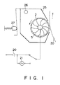
- the above-mentioned main charging apparatus is accommodated in a box 25 of which the one surface is open, the box 25 is pivotally held by a support shaft 26 that is secured to a machine frame (not shown) such as of a copying machine and is urged by such a means as a pushing spring 27 or the like, so that both end portions of the flexible sheet 2 come into contact with both end portions of the photosensitive drum 30 (see Fig. 1).
- a machine frame not shown
- a pushing spring 27 such a means as a pushing spring 27 or the like
- the present invention furthermore, it is desired to fit a rubber ring 11 on the inside of the flange ring 6 in the axial direction, so that the end portions of the flexible sheet 2 are effectively press-contacted to the end portions of the photosensitive drum 30, enabling the flexible roller 1 to be reliably driven by the photosensitive drum 30.
- the rubber ring 11 is indented by the pushing force of the pushing spring 27, and a portion 28 of the flexible sheet 2 thereon comes into surface contact with the surface of the photosensitive drum 30 maintaining a predetermined width. Therefore, a predetermined nip width is maintained between the two, and the photosensitive drum 30 can be effectively contact-charged.
- the rubber ring 11 may be replaced by any other elastic member such as a sponge obtained by foaming, for example, an urethane resin, or a ring-like felt.
- the endless, flexible and electrically conducting sheet 2 in the flexible, hollow and electrically conducting roller 1 is driven at a speed in synchronism with the rotational speed of the photosensitive drum 30, the flexible sheet 2 is brought into contact with the whole surface of the photosensitive drum 30 in the axial direction maintaining a predetermined nip width while rotating the brush 5, and under this state, a predetermined charging voltage is applied to the brush roller 3 to electrically charge the photosensitive drum 30.
- the brush roller 3 is rotated in the same direction as the hollow and electrically conducting roller 1 at a peripheral speed of from 0.9 to 0.95 times as great as the peripheral speed of the roller 1, i.e., of the moving speed of the photosensitive drum.
- the brush roller 3 With the speed of the brush roller 3 being slightly lower than that of the hollow and electrically conducting roller 1, the brush roller 3 produces a braking action relative to the roller 1 to further effectively prevent the roller 1 from being twisted.
- the flexible, endless and electrically conducting sheet 2 can be made of any material provided it is electrically conducting and is flexible.
- the electrically conducting sheet 2 can be made of an electrically conducting resin or rubber, a metal such as a foil, or a laminated material of a metal and a resin or a rubber.
- the electrically conducting resin or rubber there can be used resins or rubbers blended with a variety of electric conduction-imparting agents.
- resins include a variety of thermoplastic elastomers such as polyester elastomer, polyamide elastomer, urethane elastomer, soft vinyl chloride resin, styrene-butadiene-styrene block copolymer elastomer, and acrylic elastomer, as well as polyamides, copolyamides or modified products such as nylon 6, nylon 6,6, nylon 6-nylon 6,6 copolymer, nylon 6,6-nylon 6,10 copolymer and alkoxymethylated nylon such as methoxymethylated nylon.
- the resins that can be used are not limited thereto only as a matter of course, but may include silicone resin, acetal resins such as polyvinyl butyral, as well as polyvinyl acetate, ethylene-vinyl acetate copolymer and ionomer.
- the rubbers may be natural rubber, butadiene rubber, styrene rubber, butadiene-styrene rubber, nitrile-butadiene rubber, ethylene-propylene copolymer rubber, ethylene-propylene non-conjugated diene copolymer rubber, chloroprene rubber, butyl rubber, silicone rubber, urethane rubber and acrylic rubber.
- Examples of the electric conduction-imparting agent to be blended into the resins or the rubbers include electrically conducting carbon black, metal powders such as of silver, gold, copper, brass, nickel, aluminum and stainless steel, and powdery electric conduction-imparting agent such as tin oxide electric conduction-imparting agent.
- electrically conducting carbon black metal powders such as of silver, gold, copper, brass, nickel, aluminum and stainless steel
- powdery electric conduction-imparting agent such as tin oxide electric conduction-imparting agent.
- nonionic, anionic, cationic and amphoteric organic electric conduction-imparting agent there can be further used nonionic, anionic, cationic and amphoteric organic electric conduction-imparting agent, and an organotin electric conduction-imparting agent.
- the electrically conducting resin or rubber usually has an electric resistance (resistivity) of from 10 to 108 ⁇ ⁇ cm and, particularly, from 102 to 106 ⁇ ⁇ cm.
- the electric conduction-imparting agent is blended in an amount of from 1 to 20 parts by weight and, particularly, from 5 to 15 parts by weight per 100 parts by weight of the resin or the rubber, such that the above-mentioned resistance is obtained.
- a high electric conduction is obtained when the electric conduction-imparting agent grains form a chain structure in the resin or the rubber. In this case, however, high-potential dots may generate when a voltage is applied giving rise to the occurrence of irregular charging.
- the electric conduction-imparting agent should be uniformly and finely dispersed in the resin or the rubber.
- an acid-modified resin or rubber copolymerized with an ethylenically unsaturated carboxylic acid such as acrylic acid, methacrylic acid or maleic anhydride.
- the above-mentioned flexible and electrically conducting sheet 2 should have a thickness of usually from 50 to 400 ⁇ m and, particularly, from 100 to 300 ⁇ m though it may vary depending upon the flexibility required. It is further desired that the surface is as smooth as possible, and has an average coarseness of 5 ⁇ m or smaller and, particularly, 1 ⁇ m or smaller in compliance with JIS B 0601.
- a seamless metal foil can be used as the flexible and electrically conducting sheet 2.
- the metal foil there can be exemplified nickel, aluminum, copper, brass and tin which can be obtained by the electrocasting method or the extrusion method.
- the metal foil should have a thickness of from 20 to 80 ⁇ m and, particularly, from 30 to 50 ⁇ m.
- the flexible and electrically conducting sheet 2 may be made of a material of a single layer or a material of laminated layers.
- the surface of the electrically conducting sheet 2 that comes into contact with the surface of the photosensitive material is formed by a layer having a high resistance, there is obtained an advantage in that leakage such as electric discharge is prevented even when there exist such defects as pinholes and the like in the surface of the photosensitive material.
- the high-resistance layer should have a resistivity of from 108 to 1013 ⁇ ⁇ cm and, particularly, from 109 to 1012 ⁇ ⁇ cm, and should have a thickness of from 40 to 60 ⁇ m.
- the electric resistance can be easily adjusted by adjusting the amount of the electric conduction-imparting agent that is mixed into the resin or the rubber.
- a fluorine-containing resin or rubber such as vinylidene polyfluoride (PVDF), polytetrafluoroethylene (PTFE), tetrafluoroethylene-hexafluoropropylene copolymer (PTFE ⁇ HFP) and perfluoroalkoxy fluorine-containing resin in addition to the above-mentioned examples.
- PVDF vinylidene polyfluoride
- PTFE polytetrafluoroethylene
- PTFE ⁇ HFP tetrafluoroethylene-hexafluoropropylene copolymer
- perfluoroalkoxy fluorine-containing resin perfluoroalkoxy fluorine-containing resin
- the brush 5 that is favorably used is obtained by studding an electrically conducting brush made of an electrically conducting organic or inorganic fiber onto the electrically conducting roller.
- the brush should have a volume resistivity of from 102 to 108 ⁇ ⁇ cm and, particularly, from 103 to 106 ⁇ ⁇ cm.
- the brush fiber should have a thickness of from 2 to 10 denier (d) and, particularly, from 3 to 6 d, should have a fiber length (length of hair) of from 2 to 7 mm and, particularly, from 3 to 5 mm, and a hair density of from 10,000 to 200,000 hairs/sq. in. and, particularly, from 30,000 to 100,000 hairs/sq. in. from the standpoint of imparting smooth and uniform pushing force.
- the tips of the brush should be rounded to suppress the wear of the flexible sheet 2.
- the organic electrically conducting fiber there can be used a synthetic or a regenerated fiber in which the electric conduction-imparting agent grains are dispersed, such as polyamide fiber, e.g., nylon 6, nylon 6,6, polyester fiber, e.g., polyethylene terephthalate, acrylic fiber, polyvinyl alcohol fiber, polyvinyl chloride fiber, rayon, acetate, etc.
- the electric conduction can be imparted to the fiber not only by the method of blending the electric conduction-imparting agent but also by a method of metallizing the surfaces of the fiber.
- the electric conduction-imparting agent is to be used, the above-exemplified compounds can be used.
- the electrically conducting inorganic fiber there can be preferably used a carbon fiber as well as a metal fiber such as of a stainless steel or brass.
- a DC power source 20 is connected to the brush roller 3, and the flexible and electrically conducting sheet 2 is brought into contact with the surface of the photosensitive drum 30 that is rotating being pushed by the brush 5, and a DC voltage is applied to the electrically conducting sheet 2 via the brush 5 to electrically charge the surface of the photoconducting drum 30.
- Fig. 3 is a diagram illustrating a relationship between the voltage applied to the electrically conducting sheet 2 and the surface potential of the photosensitive drum 30 of when the charging method of the present invention is adapted to the organic photosensitive material. It will be understood from this diagram that a good linear relation is maintained between the applied voltage and the surface potential in the effective charging region.
- the potential on the surface of the photosensitive material is maintained constant at an optimum value by disposing a surface potential sensor in the periphery of the photosensitive material, and by increasing or decreasing the applied voltage based upon the surface potential detected by the sensor.
- an AC power source 21 may be used in combination with the DC power source 20 to apply a voltage which is obtained by superposing an AC voltage on the above-mentioned DC voltage.
- a preferred example of the alternating current has a frequency of from 300 to 1500 Hz and, particularly, from 400 to 1000 Hz, and an interpeak voltage of from 2.5 to 4 times as great and, particularly, from 2.8 to 3.5 times as great as the above DC voltage.
- the above-mentioned charging apparatus is very useful for electrically charging the photosensitive materials used for the electrophotographic apparatus such as copying machine, facsimile, laser printer, etc.
- a variety of organic photosensitive materials can be favorably charged irrespective of whether they have a single-layer structure or a laminated-layer structure.
- the charging apparatus can be further suitably used for contact-charging inorganic photosensitive materials such as a-Si photosensitive material, selenium photosensitive material, and the like.
- Fig. 4 illustrates the entire structure of an electrophotographic apparatus of the present invention employing the above-mentioned main charging apparatus.
- the electrophotographic apparatus comprises a photosensitive drum 51 that is rotatably provided, a main charging apparatus 52 arranged in the periphery of the photosensitive drum 51 along the direction of rotation thereof, an image-exposing mechanism 53, a developing mechanism 54, a transfer mechanism 55, a cleaning mechanism 56 and a discharging mechanism 57 by exposure to light.
- the surface of the photosensitive drum 51 is electrically charged by the main charging apparatus 52, and is exposed to the light which is bearing document image by the exposing mechanism 3, and an electrostatic latent image corresponding to the document image is formed on the surface of the photosensitive drum 51. Then, the latent image is developed by the developing mechanism 54 and a toner image is formed on the surface of the photosensitive drum 51.
- the toner image is transferred by the transfer mechanism 55 onto a predetermined paper 60 which is then carried to a known fixing mechanism which is not diagramed where the toner image is fixed by the application of heat, pressure and the like.
- the photosensitive drum 51 from which the image is transferred is brought to the cleaning mechanism 56 where the toner remaining on the surface is removed, and is then brought to the discharging mechanism 57 where the electric charge is discharged by being exposed to light. A cycle for forming image is thus completed.
- the main charging apparatus 52 used for the electrophotographic apparatus of the present invention having the above-mentioned construction is the one of the contact-charging type shown in Figs. 1 and 2.
- the main charging apparatus 52 is held being brought into contact with the surface of the photosensitive drum 51 during the step of forming image, and is held being separated away from the surface of the photosensitive drum 51 when the step for forming image is finished.
- the main charging apparatus 52 is provided with a suitable frame 70 to adjust its position, and the frame 70 is supported by a spring 72 coupled to a solenoid 71 that is secured to a machine frame (not shown).
- the up-and-down motion of the main charging apparatus 52 is controlled through the spring 72, and the hollow and electrically conducting roller 1 comes into press-contact with the surface of the photosensitive drum 51 or is separated away from the surface of the photosensitive drum 51 when the resilient force is removed.
- the up-and-down motion of the main charging apparatus 52 is controlled in relation to the cleaning mechanism 56.
- the cleaning mechanism 56 is constituted by a cleaning blade 80.
- a support plate 81 of the blade 80 is held to turn with a fulcrum 82 as a center, and the blade 80 is urged by a weight 83 provided at the end thereof to come into contact with the surface of the photosensitive drum 51.
- a solenoid 84 is provided close to the end of the support plate 81, and the blade 80 is separated away from the surface of the photosensitive drum 1 by the operation of the solenoid 84.
- operation timings of the solenoids 71 and 84 are controlled so that the cleaning blade 80 first comes into contact with the surface of the photosensitive drum 1 and that the hollow and electrically conducting roller 1 comes into press-contact with the surface of the photosensitive drum 51 being slightly lagged behind.
- the hollow and electrically conducting roller 1 is separated away from the surface of the photosensitive drum 51 and then the cleaning blade 80 is separated away from the surface of the photosensitive drum 51 being slightly lagged behind.
- Such timings can be easily adjusted by using suitable relay circuits for energizing the solenoids 71 and 84. These timings are shown, for example, in a flow chart of Fig. 5. The members are operated being controlled by a computer in compliance with this chart.
- the contact-charging by the main charging apparatus 52 is carried out under the same conditions as those of the charging apparatus of Figs. 1 and 2.
- any known developing mechanism can be used without limitation, such as a magnetic brush developing method using a magnetic developing agent of one-component type or two-component type or a method which effects the developing by carrying the electrically charged toner to the zone of developing the surface of the photosensitive drum 51 by utilizing the electrically attracting force, under the known developing conditions.
- the transfer mechanism 55 there can be used a known corona charger such as a transfer charger and as the discharging mechanism 57 by exposure to light, any mechanism can be used which permits the whole surface of the photosensitive drum 51 to be irradiated with light from a suitable source of light.
- the flexible, hollow and electrically conducting roller 1 of the main charging apparatus 52 is maintained out of contact with the photosensitive drum after the completion of the step of forming image making it possible to effectively prevent the hairs of the brush roller contained therein from falling down and to prevent the hollow and electrically conducting roller 1 from being deformed thereby, and enabling the electric charging to be carried out uniformly and stably for extended periods of time.
- the hollow and electrically conducting roller 1 is brought into contact with the surface of the photosensitive drum 51 immediately after it is cleaned, effectively preventing toners and the like left on the surface of the photosensitive material from migrating onto the roller, enabling the contact-charging to be stably carried out by the roller, and effectively preventing the photosensitive drum 51 from being contaminated again by the toner adhered to the roller.
Abstract
In an electrophotographic apparatus using a charging apparatus for contact charging, the charging apparatus comprises a flexible and hollow electrically conducting roller, made by a flexible and endless sheet (2) and an electrically conducting brush roller constituted of drive shaft and a brush (5) which is provided in the hollow roller in concentric therewith and are rotating at different speeds, wherein a charging voltage is applied to the hollow roller via the brush roller, and the photosensitive material (30) is electrically charged by rotating the hollow roller by bringing it into physical contact with the photosensitive material (30), and the hollow roller is brought at its both end portions into press-contact with the end portions on the surface of the photosensitive material (30) and is rotated being driven by the photosensitive material. In this apparatus, the hollow roller that comes into contact with the surface of the photosensitive material (30) is driven at substantially the same speed as the photosensitive material, whereby slipping and wear are effectively prevented from occurring on the surface of the photosensitive material, durability of the photosensitive material is not lost, the hollow roller that is subject to be easily deformed is effectively prevented from being twisted, enabling the electric charging to be carried out stably and uniformly for extended periods of time.
Description
- The present invention relates to an electrophotographic apparatus using a charging apparatus for mainly charging the surface of a photosensitive material by contact charging.
- In an image-forming method based upon the electrophotographic method, an image is formed by uniformly charging the surface of a photosensitive material, exposing the surface of the photosensitive material to the image-bearing light to form on the surface of the photosensitive material an electrostatic latent image that corresponds to the image of the document, and developing and transferring the electrostatic latent image.
- In such an image-forming method, the surface of the photosensitive material is usually charged (mainly charged) by the corona charging accompanied, however, by the generation of ozone which contaminates the environment. In order to avoid the generation of ozone, a method has recently been proposed to mainly charge the surface of the photosensitive material by bringing an electrically conducting rubber roller into frictional contact with the surface of the photosensitive material while applying a bias voltage (Japanese Laid-Open Patent Publications Nos. 149669/1988 and 267667/1989).
- According to the above-mentioned charging method based upon the frictional contact, however, the presence of foreign matters such as dust, paper powder, etc. between the electrically conducting rubber roller and the photosensitive material impairs the uniformity in the charging, and makes it difficult to stably carry out the charging. In forming the image, furthermore, when the surface of the photosensitive material is not so clean permitting the toner to stay thereon, then the residual toner may stick to the surface of the photosensitive material to deteriorate the durability of the photosensitive material. To carry out the uniform charging, furthermore, application of the DC bias voltage only is not sufficient and an AC bias voltage must be applied in combination.
- In order to solve the above-mentioned problems, the present applicant has previously proposed a method of effecting the frictional charging by bringing a flexible and electrically conducting sheet into frictional contact with the surface of the photosensitive material by using a charging apparatus equipped with an electrically conducting brush roller while applying a DC voltage to the above roller (see Japanese Patent Application No. 68148/1992). The charging apparatus used for the above charging method usually comprises an electrically conducting brush roller and a flexible and hollow electrically conducting roller which contains the above brush roller and is so provided as to come into contact with the brush.
- The above charging apparatus is very excellent in that the flexible and electrically conducting sheet constituting a hollow and electrically conducting roller is brought into intimate contact with the surface of the photosensitive material being pushed by the electrically conducting brush and, hence, frictional charging is uniformly carried out by simply applying a low DC bias voltage only to the electrically conducting brush without the need of applying an AC bias voltage.
- However, the flexible and electrically conducting sheet that constitutes the hollow and electrically conducting roller rotates in contact with the surface of the photosensitive material being simply pushed by the force of the brush. That is, the electrically conducting sheet rotates unstably giving rise to the occurrence of irregular rotation, slipping relative to the photosensitive material, and friction with respect to the surface of the photosensitive material. As a result, the photosensitive material is worn out and loses durability.
- Furthermore, the electrically conducting sheet is usually very thin and may be twisted by the rotational driving force of the brush roller, resulting in the development of irregular charging. Moreover, the electrically conducting sheet may be broken as it is twisted constantly and more greatly.
- According to the above charging apparatus in which the hollow and electrically conducting roller is press-contacted to the surface of the photosensitive material by the electrically conducting brush that is contained therein, hairs of the electrically conducting brush remain fallen down permanently when the copying operation is not carried out for extended periods of time. Consequently, the hollow and electrically conducting roller is deformed and makes it difficult to carry out the uniform charging. Moreover, foreign matters such as toner and dust adhered onto the surface of the photosensitive material migrate onto the surface of the hollow and electrically conducting roller and build up thereon. After used for extended periods of time, therefore, troubles develop such as irregular charging giving damage to the surface of the photosensitive material, which is a problem from the standpoint of life of the apparatus.
- The object of the present invention therefore is to provide an electrophotographic apparatus using a charging apparatus which is capable of stably and uniformly charging the photosensitive material by the contact charging without causing the electrically conducting sheet press-contacted to the surface of the photosensitive material to be twisted and without causing the photosensitive material to lose its durability.
- Another object of the present invention is to provide an electrophotographic apparatus which uses the charging apparatus of the above contact charging type as an apparatus for mainly charging the photosensitive material, wherein the surface of the photosensitive material is uniformly and stably charged for extended periods of time.
- According to the present invention, there is provided an electrophotographic apparatus comprising a movable photosensitive material, a main charging apparatus, an image-exposing mechanism, a developing mechanism, a transfer mechanism and a cleaning member which are arranged in the order mentioned along the moving direction of the photosensitive material, wherein said main charging apparatus comprises a flexible, hollow and electrically conducting roller and an electrically conducting brush roller provided in said hollow roller in concentric therewith and to rotate relative to each other, and the electric charging of the photosensitive material is carried out by rotating the hollow roller applied with a charging voltage via the brush roller and physically contacting the hollow roller to the photosensitive material, the improvement characterized in that the hollow roller is brought at its both end portions into press-contact with the end portions on the surface of the photosensitive material and is rotated being driven by the photosensitive material.
- According to the charging apparatus used in the present invention, the flexible and hollow electrically conducting roller (hollow roller) is press-contacted at its both end portions to the end portions on the surface of the photosensitive material and, hence, rotates at substantially the same speed (peripheral speed) as the photosensitive material being driven thereby. Therefore, no slipping takes place between the photosensitive material and the hollow roller, and the photosensitive material is effectively prevented from being worn out and is further effectively liberated from the problem of losing durability. Moreover, the hollow roller is forcibly driven by the photosensitive material as it is press-contacted thereto; i.e., the hollow roller is effectively prevented from being twisted, and the electric charging is carried out stably and uniformly.
- Both end portions of the hollow roller can be easily press-contacted by the charging apparatus in which the hollow roller is installed in a box having an opening and is placed near the opening, the box being allowed to turn with respect to the photosensitive material and the machine frame, and by urging the box toward the photosensitive material using a resilient member such as a leaf spring or the like. It is further allowable to provide both end portions of an endless, flexible and electrically conducting sheet constituting the hollow roller on the ring-like roller flange via an elastic member such as a rubber ring, and to press-contact both end portions by utilizing the elastic force thereof. In this case, the roller flange is provided on the shaft of the electrically conducting brush roller to rotate independently.
- In the charging apparatus of the present invention, furthermore, the hollow roller contacting to the surface of the photosensitive material is flexible and is freely deformable, and is hence pushed by the electrically conducting brush roller. Therefore, even in case foreign matters such as dust, paper powder and residual toner are adhered on the surface of the photosensitive material, uniform contact is accomplished between the surface of the photosensitive material other than the portions where foreign matters are adhered and the hollow roller. Moreover, since the individual ears of the brush of the brush roller work as pushing springs, fine and intimate contact is accomplished between the surface of the photosensitive material and the hollow roller. That is, a uniform surface contact is accomplished between the two, making it possible to carry out uniform electric charging.
- According to the present invention, furthermore, there is provided an electrophotographic apparatus using the above-mentioned charging apparatus as the main charging apparatus, wherein the hollow roller and the cleaning member of the main charging apparatus are adjustably provided so as to come into contact with the surface of the photosensitive material during the step of forming image and come out of contact with the surface of the photosensitive material after the completion of the step of forming image, the hollow roller is brought into contact with the surface of the photosensitive material after the cleaning member is brought into contact with the surface of the photosensitive material, and the hollow roller is separated away from the surface of the photosensitive material before the cleaning member is separated away from the surface of the photosensitive material.
- According to the above electrophotographic apparatus, the hollow roller constituting the main charging apparatus is located being separated away from the surface of the photosensitive material. Therefore, no pressure is exerted from the surface of the photosensitive material upon the brush roller that is contained in the hollow roller, and the hairs of the brush are effectively prevented from falling down and the hollow roller is effectively prevented from deforming.
- In a state in which the hollow roller is held in contact with the surface of the photosensitive material during the step of forming image, furthermore, the cleaning member is held in contact with the photosensitive material at all times. That is, the surface of the photosensitive material in which the hollow roller is in contact is always in a state of just after being cleaned. The present invention, therefore, makes it possible to effectively avoid such an inconvenience that foreign matter such as toner and dust migrate and build up on the hollow roller that mainly effects the electric charging. Accordingly, the electric charging can be carried out uniformly and stably without causing damage to the surface of the photosensitive material, and enabling good image to be obtained for extended periods of time.
-
- Fig. 1 is a side sectional view of a charging apparatus used as a main charging apparatus in the present invention together with a photosensitive drum;
- Fig. 2 is a front sectional view of the charging apparatus of Fig. 1;
- Fig. 3 is a diagram illustrating a relationship between the applied voltage and the surface potential of a photosensitive material of when an organic photosensitive material is electrically charged by the charging apparatus of Fig. 1;
- Fig. 4 is a diagram which schematically illustrates the whole structure of an electrophotographic apparatus of the present invention employing the charging apparatus of Fig. 1; and
- Fig. 5 is a flow chart illustrating the timings for driving the electrically conducting roller (charging roller) and the cleaning member in the electrophotographic apparatus of Fig. 4.
- Referring to Figs. 1 and 2, the main charging apparatus roughly comprises a hollow and electrically conducting
roller 1 made up of a flexible, endless and electrically conductingsheet 2 andrigid flange rings 6 provided at both end portions thereof, and an electrically conductingbrush roller 3 provided in theflexible roller 1 in concentric therewith and to rotate relative to each other. Thebrush roller 3 is constituted by a drive shaft 4 and abrush 5 studded on the above shaft. - The inner surface of the flexible electrically conducting
sheet 2 in theflexible roller 1 is in contact with thebrush 5 of the electrically conductingbrush roller 3 that is accommodated therein, and is supported by thebrush 5. - Both end portions of the
flexible sheet 2 are fastened to theflange rings 6 using an adhesive or the like. Theflange rings 6 are fitted to the drive shaft by using abearing 7 so as to rotate relative thereto. That is, both end portions of thesheet 2 are fastened to theflange rings 6 and can, hence, be press-contacted to the end portions of thephotosensitive drum 30 very stably, so that theflexible roller 1 is driven without any difference in the peripheral speed from the surface of the drum.
The drive shaft 4 of thebrush roller 3 is coupled to asuitable drive member 20 such as a belt pulley, enabling thebrush roller 3 to be driven independently of theflexible roller 1. - The above-mentioned main charging apparatus is accommodated in a
box 25 of which the one surface is open, thebox 25 is pivotally held by asupport shaft 26 that is secured to a machine frame (not shown) such as of a copying machine and is urged by such a means as a pushingspring 27 or the like, so that both end portions of theflexible sheet 2 come into contact with both end portions of the photosensitive drum 30 (see Fig. 1). Thus, both end portions of theflexible sheet 2 are press-contacted to both end portions of thephotosensitive drum 30, and theflexible roller 1 is driven without any difference in the peripheral speed from thephotosensitive drum 30. - According to the present invention, furthermore, it is desired to fit a rubber ring 11 on the inside of the
flange ring 6 in the axial direction, so that the end portions of theflexible sheet 2 are effectively press-contacted to the end portions of thephotosensitive drum 30, enabling theflexible roller 1 to be reliably driven by thephotosensitive drum 30. - In this case, in particular, the rubber ring 11 is indented by the pushing force of the pushing
spring 27, and aportion 28 of theflexible sheet 2 thereon comes into surface contact with the surface of thephotosensitive drum 30 maintaining a predetermined width. Therefore, a predetermined nip width is maintained between the two, and thephotosensitive drum 30 can be effectively contact-charged. - So long as the surface contact between the
portion 28 of theflexible sheet 2 and thedrum 30 is accomplished by the pushing force of the pushingspring 27, the rubber ring 11 may be replaced by any other elastic member such as a sponge obtained by foaming, for example, an urethane resin, or a ring-like felt. - To place the
flexible sheet 2 in position, furthermore, it is desired to provide acoil spring 13 between the end portion of thebrush 5 and the inner end of theflange ring 6 in the axial direction to impart some tension to theflexible sheet 2 in the axial direction. - According to the present invention as described above, the endless, flexible and electrically conducting
sheet 2 in the flexible, hollow and electrically conductingroller 1 is driven at a speed in synchronism with the rotational speed of thephotosensitive drum 30, theflexible sheet 2 is brought into contact with the whole surface of thephotosensitive drum 30 in the axial direction maintaining a predetermined nip width while rotating thebrush 5, and under this state, a predetermined charging voltage is applied to thebrush roller 3 to electrically charge thephotosensitive drum 30. In this case, it is desired that thebrush roller 3 is rotated in the same direction as the hollow and electrically conductingroller 1 at a peripheral speed of from 0.9 to 0.95 times as great as the peripheral speed of theroller 1, i.e., of the moving speed of the photosensitive drum. With the speed of thebrush roller 3 being slightly lower than that of the hollow and electrically conductingroller 1, thebrush roller 3 produces a braking action relative to theroller 1 to further effectively prevent theroller 1 from being twisted. - In the above-mentioned main charging apparatus, the flexible, endless and electrically conducting
sheet 2 can be made of any material provided it is electrically conducting and is flexible. For instance. the electrically conductingsheet 2 can be made of an electrically conducting resin or rubber, a metal such as a foil, or a laminated material of a metal and a resin or a rubber. - As the electrically conducting resin or rubber, there can be used resins or rubbers blended with a variety of electric conduction-imparting agents. Preferred examples of such resins include a variety of thermoplastic elastomers such as polyester elastomer, polyamide elastomer, urethane elastomer, soft vinyl chloride resin, styrene-butadiene-styrene block copolymer elastomer, and acrylic elastomer, as well as polyamides, copolyamides or modified products such as
nylon 6,nylon nylon nylon 6,6-nylon 6,10 copolymer and alkoxymethylated nylon such as methoxymethylated nylon. The resins that can be used are not limited thereto only as a matter of course, but may include silicone resin, acetal resins such as polyvinyl butyral, as well as polyvinyl acetate, ethylene-vinyl acetate copolymer and ionomer. The rubbers may be natural rubber, butadiene rubber, styrene rubber, butadiene-styrene rubber, nitrile-butadiene rubber, ethylene-propylene copolymer rubber, ethylene-propylene non-conjugated diene copolymer rubber, chloroprene rubber, butyl rubber, silicone rubber, urethane rubber and acrylic rubber. - Examples of the electric conduction-imparting agent to be blended into the resins or the rubbers include electrically conducting carbon black, metal powders such as of silver, gold, copper, brass, nickel, aluminum and stainless steel, and powdery electric conduction-imparting agent such as tin oxide electric conduction-imparting agent. There can be further used nonionic, anionic, cationic and amphoteric organic electric conduction-imparting agent, and an organotin electric conduction-imparting agent.
- It is desired that the electrically conducting resin or rubber usually has an electric resistance (resistivity) of from 10 to 10⁸ Ω · cm and, particularly, from 10² to 10⁶ Ω · cm. Though it may vary depending upon the kind thereof, the electric conduction-imparting agent is blended in an amount of from 1 to 20 parts by weight and, particularly, from 5 to 15 parts by weight per 100 parts by weight of the resin or the rubber, such that the above-mentioned resistance is obtained. In general, a high electric conduction is obtained when the electric conduction-imparting agent grains form a chain structure in the resin or the rubber. In this case, however, high-potential dots may generate when a voltage is applied giving rise to the occurrence of irregular charging. Therefore, the electric conduction-imparting agent should be uniformly and finely dispersed in the resin or the rubber. For this purpose, it is important to sufficiently knead the resin or the rubber blended with the electric conduction-imparting agent. To uniformly and effectively disperse the electric conduction-imparting agent, furthermore, it is recommended to partly use an acid-modified resin or rubber copolymerized with an ethylenically unsaturated carboxylic acid such as acrylic acid, methacrylic acid or maleic anhydride.
- The above-mentioned flexible and electrically conducting
sheet 2 should have a thickness of usually from 50 to 400 µm and, particularly, from 100 to 300 µm though it may vary depending upon the flexibility required. It is further desired that the surface is as smooth as possible, and has an average coarseness of 5 µm or smaller and, particularly, 1 µm or smaller in compliance with JIS B 0601. - According to the present invention, furthermore, a seamless metal foil can be used as the flexible and electrically conducting
sheet 2. As the metal foil, there can be exemplified nickel, aluminum, copper, brass and tin which can be obtained by the electrocasting method or the extrusion method. The metal foil should have a thickness of from 20 to 80 µm and, particularly, from 30 to 50 µm. - The flexible and electrically conducting
sheet 2 may be made of a material of a single layer or a material of laminated layers. When the surface of theelectrically conducting sheet 2 that comes into contact with the surface of the photosensitive material is formed by a layer having a high resistance, there is obtained an advantage in that leakage such as electric discharge is prevented even when there exist such defects as pinholes and the like in the surface of the photosensitive material. The high-resistance layer should have a resistivity of from 10⁸ to 10¹³ Ω · cm and, particularly, from 10⁹ to 10¹² Ω · cm, and should have a thickness of from 40 to 60 µm. The electric resistance can be easily adjusted by adjusting the amount of the electric conduction-imparting agent that is mixed into the resin or the rubber. As the electric conduction-imparting agent and the rubber, there can be further used a fluorine-containing resin or rubber, such as vinylidene polyfluoride (PVDF), polytetrafluoroethylene (PTFE), tetrafluoroethylene-hexafluoropropylene copolymer (PTFE· HFP) and perfluoroalkoxy fluorine-containing resin in addition to the above-mentioned examples. When these resins or rubbers are used as the high-resistance layer, a great advantage is obtained with respect to life of the photosensitive material and life of the sheet since they are inert and have small coefficients of friction. - According to the present invention, the
brush 5 that is favorably used is obtained by studding an electrically conducting brush made of an electrically conducting organic or inorganic fiber onto the electrically conducting roller. The brush should have a volume resistivity of from 10² to 10⁸ Ω · cm and, particularly, from 10³ to 10⁶ Ω · cm. The brush fiber should have a thickness of from 2 to 10 denier (d) and, particularly, from 3 to 6 d, should have a fiber length (length of hair) of from 2 to 7 mm and, particularly, from 3 to 5 mm, and a hair density of from 10,000 to 200,000 hairs/sq. in. and, particularly, from 30,000 to 100,000 hairs/sq. in. from the standpoint of imparting smooth and uniform pushing force. Furthermore, the tips of the brush should be rounded to suppress the wear of theflexible sheet 2. - As the organic electrically conducting fiber, there can be used a synthetic or a regenerated fiber in which the electric conduction-imparting agent grains are dispersed, such as polyamide fiber, e.g.,
nylon 6,nylon - According to the present invention, a
DC power source 20 is connected to thebrush roller 3, and the flexible and electrically conductingsheet 2 is brought into contact with the surface of thephotosensitive drum 30 that is rotating being pushed by thebrush 5, and a DC voltage is applied to the electrically conductingsheet 2 via thebrush 5 to electrically charge the surface of thephotoconducting drum 30. - It is desired that the charging voltage applied to the electrically conducting
sheet 2 is set to be from 1.5 to 3.5 times as great and, particularly, from 2 to 3 times as great as the charge starting voltage on the surface of thephotosensitive drum 30. Fig. 3 is a diagram illustrating a relationship between the voltage applied to the electrically conductingsheet 2 and the surface potential of thephotosensitive drum 30 of when the charging method of the present invention is adapted to the organic photosensitive material. It will be understood from this diagram that a good linear relation is maintained between the applied voltage and the surface potential in the effective charging region. It will therefore be understood that in the charging method of the present invention, the potential on the surface of the photosensitive material is maintained constant at an optimum value by disposing a surface potential sensor in the periphery of the photosensitive material, and by increasing or decreasing the applied voltage based upon the surface potential detected by the sensor. - According to the present invention, uniform charging without irregularity is accomplished by using a DC voltage only. To effect the charging more uniformly, furthermore, an
AC power source 21 may be used in combination with theDC power source 20 to apply a voltage which is obtained by superposing an AC voltage on the above-mentioned DC voltage. A preferred example of the alternating current has a frequency of from 300 to 1500 Hz and, particularly, from 400 to 1000 Hz, and an interpeak voltage of from 2.5 to 4 times as great and, particularly, from 2.8 to 3.5 times as great as the above DC voltage. - The above-mentioned charging apparatus is very useful for electrically charging the photosensitive materials used for the electrophotographic apparatus such as copying machine, facsimile, laser printer, etc. A variety of organic photosensitive materials can be favorably charged irrespective of whether they have a single-layer structure or a laminated-layer structure. The charging apparatus can be further suitably used for contact-charging inorganic photosensitive materials such as a-Si photosensitive material, selenium photosensitive material, and the like.
- Fig. 4 illustrates the entire structure of an electrophotographic apparatus of the present invention employing the above-mentioned main charging apparatus.
- The electrophotographic apparatus comprises a
photosensitive drum 51 that is rotatably provided, amain charging apparatus 52 arranged in the periphery of thephotosensitive drum 51 along the direction of rotation thereof, an image-exposingmechanism 53, a developingmechanism 54, atransfer mechanism 55, acleaning mechanism 56 and a dischargingmechanism 57 by exposure to light. - That is, the surface of the
photosensitive drum 51 is electrically charged by themain charging apparatus 52, and is exposed to the light which is bearing document image by the exposingmechanism 3, and an electrostatic latent image corresponding to the document image is formed on the surface of thephotosensitive drum 51. Then, the latent image is developed by the developingmechanism 54 and a toner image is formed on the surface of thephotosensitive drum 51. The toner image is transferred by thetransfer mechanism 55 onto apredetermined paper 60 which is then carried to a known fixing mechanism which is not diagramed where the toner image is fixed by the application of heat, pressure and the like. Thephotosensitive drum 51 from which the image is transferred is brought to thecleaning mechanism 56 where the toner remaining on the surface is removed, and is then brought to the dischargingmechanism 57 where the electric charge is discharged by being exposed to light. A cycle for forming image is thus completed. - The
main charging apparatus 52 used for the electrophotographic apparatus of the present invention having the above-mentioned construction is the one of the contact-charging type shown in Figs. 1 and 2. In this photographic apparatus, themain charging apparatus 52 is held being brought into contact with the surface of thephotosensitive drum 51 during the step of forming image, and is held being separated away from the surface of thephotosensitive drum 51 when the step for forming image is finished. Themain charging apparatus 52 is provided with asuitable frame 70 to adjust its position, and theframe 70 is supported by aspring 72 coupled to asolenoid 71 that is secured to a machine frame (not shown). By energizing thesolenoid 71, the up-and-down motion of themain charging apparatus 52 is controlled through thespring 72, and the hollow and electrically conductingroller 1 comes into press-contact with the surface of thephotosensitive drum 51 or is separated away from the surface of thephotosensitive drum 51 when the resilient force is removed. - According to the present invention, the up-and-down motion of the
main charging apparatus 52 is controlled in relation to thecleaning mechanism 56. - The
cleaning mechanism 56 is constituted by acleaning blade 80. Here, for instance, asupport plate 81 of theblade 80 is held to turn with a fulcrum 82 as a center, and theblade 80 is urged by aweight 83 provided at the end thereof to come into contact with the surface of thephotosensitive drum 51. Asolenoid 84 is provided close to the end of thesupport plate 81, and theblade 80 is separated away from the surface of thephotosensitive drum 1 by the operation of thesolenoid 84. - That is, to start the image formation according to the present invention, operation timings of the
solenoids cleaning blade 80 first comes into contact with the surface of thephotosensitive drum 1 and that the hollow and electrically conductingroller 1 comes into press-contact with the surface of thephotosensitive drum 51 being slightly lagged behind. To end the step of image formation, the hollow and electrically conductingroller 1 is separated away from the surface of thephotosensitive drum 51 and then thecleaning blade 80 is separated away from the surface of thephotosensitive drum 51 being slightly lagged behind. Such timings can be easily adjusted by using suitable relay circuits for energizing thesolenoids - In the above-mentioned electrophotographic apparatus, the contact-charging by the
main charging apparatus 52 is carried out under the same conditions as those of the charging apparatus of Figs. 1 and 2. - As the image-exposing
mechanism 53, there can be employed any known mechanism in which the surface of thephotosensitive drum 51 is irradiated with the reflected light of document through an optical system. As the developingmechanism 54, furthermore, any known developing mechanism can be used without limitation, such as a magnetic brush developing method using a magnetic developing agent of one-component type or two-component type or a method which effects the developing by carrying the electrically charged toner to the zone of developing the surface of thephotosensitive drum 51 by utilizing the electrically attracting force, under the known developing conditions. - As the
transfer mechanism 55, there can be used a known corona charger such as a transfer charger and as the dischargingmechanism 57 by exposure to light, any mechanism can be used which permits the whole surface of thephotosensitive drum 51 to be irradiated with light from a suitable source of light. - By using the above-mentioned electrophotographic apparatus, the flexible, hollow and electrically conducting
roller 1 of themain charging apparatus 52 is maintained out of contact with the photosensitive drum after the completion of the step of forming image making it possible to effectively prevent the hairs of the brush roller contained therein from falling down and to prevent the hollow and electrically conductingroller 1 from being deformed thereby, and enabling the electric charging to be carried out uniformly and stably for extended periods of time. - Furthermore, the hollow and electrically conducting
roller 1 is brought into contact with the surface of thephotosensitive drum 51 immediately after it is cleaned, effectively preventing toners and the like left on the surface of the photosensitive material from migrating onto the roller, enabling the contact-charging to be stably carried out by the roller, and effectively preventing thephotosensitive drum 51 from being contaminated again by the toner adhered to the roller.
Claims (6)
- An electrophotographic apparatus comprising a movable photosensitive material, a main charging apparatus, an image-exposing mechanism, a developing mechanism, a transfer mechanism and a cleaning member which are arranged in the order mentioned along the moving direction of the photosensitive material, wherein said main charging apparatus comprises a flexible, hollow and electrically conducting roller and an electrically conducting brush roller provided in said hollow roller concentric therewith and to rotate relative to each other, and the electric charging of the photosensitive material is carried out by rotating the hollow roller applied with a charging voltage via the brush roller and physically contacting the hollow roller to the photosensitive material, the improvement characterized in that the hollow roller is brought at its both end portions into press-contact with the end portions on the surface of the photosensitive material and is rotated being driven by the photosensitive material.
- An electrophotographic apparatus according to claim 1, wherein said hollow roller is constituted by an endless, flexible and electrically conducting sheet, and both end portions of said sheet are provided on the shaft of the brush roller so as to rotate independently thereof.
- An electrophotographic apparatus according to claim 2, wherein an elastic member is provided between both end portions of said flexible and electrically conducting sheet and the roller flange, and both end portions of said hollow roller are press-contacted by the elastic force of said resilient member.
- An electrophotographic apparatus according to claim 3, wherein said elastic member is a rubber ring fitted into the roller flange.
- An electrophotographic apparatus according to claim 1, wherein during the step of charging, the whole surface of the hollow roller is brought into intimate contact with the surface of the photosensitive material and is rotated being driven by the photosensitive material with both end portions of said hollow roller being press-contacted to the end portions on the surface of the photosensitive material, the hollow roller and the cleaning member are adjustably provided so as to come into contact with the surface of the photosensitive material during the step of forming image and come out of contact with the surface of the photosensitive material after the completion of the step of forming image, the hollow roller is brought into contact with the surface of the photosensitive material after the cleaning member is brought into contact with the surface of the photosensitive material, and the hollow roller is separated away from the surface of the photosensitive material before the cleaning member is separated away from the surface of the photosensitive material.
- An electrophotographic apparatus according to claim 5, wherein the hollow roller and said cleaning member are held in a manner that their positions can be adjusted by solenoids.
Applications Claiming Priority (4)
| Application Number | Priority Date | Filing Date | Title |
|---|---|---|---|
| JP12927193 | 1993-05-31 | ||
| JP129271/93 | 1993-05-31 | ||
| JP16220493 | 1993-06-30 | ||
| JP162204/93 | 1993-06-30 |
Publications (2)
| Publication Number | Publication Date |
|---|---|
| EP0629929A2 true EP0629929A2 (en) | 1994-12-21 |
| EP0629929A3 EP0629929A3 (en) | 1995-11-22 |
Family
ID=26464717
Family Applications (1)
| Application Number | Title | Priority Date | Filing Date |
|---|---|---|---|
| EP94303905A Withdrawn EP0629929A3 (en) | 1993-05-31 | 1994-05-31 | Electrophotographic apparatus. |
Country Status (4)
| Country | Link |
|---|---|
| US (1) | US5483323A (en) |
| EP (1) | EP0629929A3 (en) |
| CN (1) | CN1097876A (en) |
| TW (1) | TW272259B (en) |
Families Citing this family (25)
| Publication number | Priority date | Publication date | Assignee | Title |
|---|---|---|---|---|
| EP0646849A3 (en) * | 1993-09-30 | 1995-07-26 | Mita Industrial Co Ltd | Method and apparatus for charging electrically. |
| US5678129A (en) * | 1994-09-29 | 1997-10-14 | Ricoh Company, Ltd. | Image forming apparatus with contact type charging member |
| US5842081A (en) * | 1995-05-31 | 1998-11-24 | Fuji Xerox Co., Ltd. | Method and apparatus for charging an electrographic photoreceptor |
| JPH0973211A (en) * | 1995-09-05 | 1997-03-18 | Canon Inc | Electrostatic charge member, process cartridge and image forming device |
| US5914742A (en) * | 1996-11-27 | 1999-06-22 | Lexmark International, Inc. | Primary charge roller with protruding end |
| US5758229A (en) * | 1997-03-10 | 1998-05-26 | Samsung Electronic Co., Ltd. | Method of controlling the charging operation of the contact charger of an electrophotographic apparatus to prevent the contact charger from being contaminated |
| WO2000006470A2 (en) | 1998-07-31 | 2000-02-10 | Shuttleworth, Inc. | Low electrostatic discharge conveyor |
| US6131235A (en) * | 1998-08-04 | 2000-10-17 | Illinois Tool Works Inc. | Adjustable brush holder for web cleaning systems |
| JP2001109332A (en) * | 1999-10-01 | 2001-04-20 | Canon Inc | Image forming device |
| JP4343668B2 (en) * | 2003-12-11 | 2009-10-14 | キヤノン株式会社 | Developing device, cartridge, and image forming apparatus |
| US7558522B2 (en) * | 2006-04-04 | 2009-07-07 | Kabushiki Kaisha Toshiba | Image forming apparatus having toner cleaner and toner cleaning method |
| JP4544341B2 (en) * | 2008-04-30 | 2010-09-15 | 富士ゼロックス株式会社 | Charging apparatus, image forming assembly using the same, and image forming apparatus |
| JP5534995B2 (en) * | 2010-07-30 | 2014-07-02 | キヤノン株式会社 | Image forming apparatus |
| US9072646B2 (en) | 2010-12-14 | 2015-07-07 | Allen Medical Systems, Inc. | Lateral surgical platform with rotation |
| CN102103343A (en) * | 2011-01-28 | 2011-06-22 | 广州市易禾打印影像技术有限公司 | Method and device for reducing pollution of charging body and electrostatic carrier |
| US9498397B2 (en) | 2012-04-16 | 2016-11-22 | Allen Medical Systems, Inc. | Dual column surgical support system |
| US20170176883A1 (en) * | 2014-08-18 | 2017-06-22 | Hewlett-Packard Development Company, L.P. | Printing using a metal-surface charging element |
| US10492973B2 (en) | 2015-01-05 | 2019-12-03 | Allen Medical Systems, Inc. | Dual modality prone spine patient support apparatuses |
| US9655793B2 (en) | 2015-04-09 | 2017-05-23 | Allen Medical Systems, Inc. | Brake release mechanism for surgical table |
| US10561559B2 (en) | 2015-10-23 | 2020-02-18 | Allen Medical Systems, Inc. | Surgical patient support system and method for lateral-to-prone support of a patient during spine surgery |
| US10363189B2 (en) | 2015-10-23 | 2019-07-30 | Allen Medical Systems, Inc. | Surgical patient support for accommodating lateral-to-prone patient positioning |
| US10548793B2 (en) | 2016-06-14 | 2020-02-04 | Allen Medical Systems, Inc. | Pinless loading for spine table |
| US11213448B2 (en) | 2017-07-31 | 2022-01-04 | Allen Medical Systems, Inc. | Rotation lockout for surgical support |
| US11202731B2 (en) | 2018-02-28 | 2021-12-21 | Allen Medical Systems, Inc. | Surgical patient support and methods thereof |
| US11471354B2 (en) | 2018-08-30 | 2022-10-18 | Allen Medical Systems, Inc. | Patient support with selectable pivot |
Citations (5)
| Publication number | Priority date | Publication date | Assignee | Title |
|---|---|---|---|---|
| JPS60205551A (en) * | 1984-03-30 | 1985-10-17 | Fuji Xerox Co Ltd | Electrifying device |
| EP0443800A2 (en) * | 1990-02-17 | 1991-08-28 | Canon Kabushiki Kaisha | A charging method and a charging device |
| EP0562857A2 (en) * | 1992-03-26 | 1993-09-29 | Mita Industrial Co. Ltd. | Electrifying method and electrifying apparatus used therefor |
| EP0590912A2 (en) * | 1992-09-28 | 1994-04-06 | Mita Industrial Co., Ltd. | Method of contact-charging the surface of a photosensitive material |
| EP0646849A2 (en) * | 1993-09-30 | 1995-04-05 | Mita Industrial Co. Ltd. | Method and apparatus for charging electrically |
Family Cites Families (11)
| Publication number | Priority date | Publication date | Assignee | Title |
|---|---|---|---|---|
| DE2939473C2 (en) * | 1979-09-28 | 1985-01-31 | Agfa-Gevaert Ag, 5090 Leverkusen | Transport roller for photographic material |
| EP0308185B1 (en) * | 1987-09-14 | 1993-11-24 | Canon Kabushiki Kaisha | A charging device |
| US5095335A (en) * | 1989-09-19 | 1992-03-10 | Canon Kabushiki Kaisha | Copier with retractable charging unit to prevent damage to drum when removing process cartridge |
| JPH03156476A (en) * | 1989-11-15 | 1991-07-04 | Canon Inc | Electrostatic charging device for image formation device |
| US5088706A (en) * | 1990-08-30 | 1992-02-18 | Jackson Roger P | Spinal surgery table |
| JP2880356B2 (en) * | 1991-10-30 | 1999-04-05 | 沖電気工業株式会社 | Image forming apparatus and image forming method |
| US5426488A (en) * | 1992-10-19 | 1995-06-20 | Sharp Kabushiki Kaisha | Method of charging a built-in electrophotographic charge member |
| US5357323A (en) * | 1992-10-26 | 1994-10-18 | Konica Corporation | Magnetic brush charging device |
| EP0598483A1 (en) * | 1992-11-16 | 1994-05-25 | Konica Corporation | Image forming apparatus with charger of image carrier using magnetic brush |
| US5367364A (en) * | 1993-05-19 | 1994-11-22 | Steven B. Michlin | Charge roller contact stabilizer spring |
| US5410386A (en) * | 1993-06-25 | 1995-04-25 | Xerox Corporation | Hollow pultruded electical contact |
-
1994
- 1994-05-28 TW TW083104935A patent/TW272259B/zh active
- 1994-05-31 EP EP94303905A patent/EP0629929A3/en not_active Withdrawn
- 1994-05-31 US US08/251,314 patent/US5483323A/en not_active Expired - Lifetime
- 1994-05-31 CN CN94105937A patent/CN1097876A/en active Pending
Patent Citations (5)
| Publication number | Priority date | Publication date | Assignee | Title |
|---|---|---|---|---|
| JPS60205551A (en) * | 1984-03-30 | 1985-10-17 | Fuji Xerox Co Ltd | Electrifying device |
| EP0443800A2 (en) * | 1990-02-17 | 1991-08-28 | Canon Kabushiki Kaisha | A charging method and a charging device |
| EP0562857A2 (en) * | 1992-03-26 | 1993-09-29 | Mita Industrial Co. Ltd. | Electrifying method and electrifying apparatus used therefor |
| EP0590912A2 (en) * | 1992-09-28 | 1994-04-06 | Mita Industrial Co., Ltd. | Method of contact-charging the surface of a photosensitive material |
| EP0646849A2 (en) * | 1993-09-30 | 1995-04-05 | Mita Industrial Co. Ltd. | Method and apparatus for charging electrically |
Non-Patent Citations (1)
| Title |
|---|
| PATENT ABSTRACTS OF JAPAN vol. 010 no. 064 (P-436) ,14 March 1986 & JP-A-60 205551 (FUJI XEROX KK) 17 October 1985, * |
Also Published As
| Publication number | Publication date |
|---|---|
| US5483323A (en) | 1996-01-09 |
| TW272259B (en) | 1996-03-11 |
| EP0629929A3 (en) | 1995-11-22 |
| CN1097876A (en) | 1995-01-25 |
Similar Documents
| Publication | Publication Date | Title |
|---|---|---|
| US5483323A (en) | Electrophotographic apparatus utilizing a hollow roller changing mechanism | |
| JPH08328403A (en) | Image forming device | |
| JP2001215799A (en) | Image forming device and process cartridge | |
| JP4208513B2 (en) | Image forming apparatus | |
| US20060039719A1 (en) | Charging device, image forming process cartridge, and image forming apparatus including the charging device | |
| EP0572738B1 (en) | Charging device, image forming apparatus and process cartridge detachably mountable to the image forming apparatus | |
| US5659853A (en) | Electrically charging method and electrically charging device used therefor | |
| JP4073262B2 (en) | Transfer member cleaning method and image forming apparatus | |
| US5485344A (en) | Method of contact-charging the surface of a photosensitive material | |
| JPH10333514A (en) | Image forming device | |
| JPH08262841A (en) | Contact electrifying device, contact transfer device, contact dveloping device, cleaning device and image forming device | |
| JPH09152788A (en) | Transfer device for image forming device | |
| JP2864782B2 (en) | Charging member | |
| JPH0798535A (en) | Electrophotographic device | |
| JP3513343B2 (en) | Image forming device | |
| JP4261933B2 (en) | Developing device, process cartridge, and image forming apparatus | |
| JP2003316130A (en) | Charging means, image forming unit using same, and image forming device | |
| JPH0695519A (en) | Image forming device | |
| JPH0764370A (en) | Electrifier | |
| JPH10333523A (en) | Image forming device | |
| JPH10260621A (en) | Image forming device | |
| JPH07168419A (en) | Electrifying method and electrifying device used therefor | |
| JPH06337570A (en) | Electrifier | |
| JPH0720683A (en) | Electrifier | |
| JPH0862927A (en) | Charging method for photorecertor applied to electrophotographic method and charging device used therefor |
Legal Events
| Date | Code | Title | Description |
|---|---|---|---|
| PUAI | Public reference made under article 153(3) epc to a published international application that has entered the european phase |
Free format text: ORIGINAL CODE: 0009012 |
|
| AK | Designated contracting states |
Kind code of ref document: A2 Designated state(s): DE FR GB IT |
|
| PUAL | Search report despatched |
Free format text: ORIGINAL CODE: 0009013 |
|
| AK | Designated contracting states |
Kind code of ref document: A3 Designated state(s): DE FR GB IT |
|
| STAA | Information on the status of an ep patent application or granted ep patent |
Free format text: STATUS: THE APPLICATION HAS BEEN WITHDRAWN |
|
| 17P | Request for examination filed |
Effective date: 19960506 |
|
| 18W | Application withdrawn |
Withdrawal date: 19960514 |