EP0629679A2 - Vent orifice in fluid catalytic cracking direct-connected cyclone apparatus - Google Patents
Vent orifice in fluid catalytic cracking direct-connected cyclone apparatus Download PDFInfo
- Publication number
- EP0629679A2 EP0629679A2 EP94303948A EP94303948A EP0629679A2 EP 0629679 A2 EP0629679 A2 EP 0629679A2 EP 94303948 A EP94303948 A EP 94303948A EP 94303948 A EP94303948 A EP 94303948A EP 0629679 A2 EP0629679 A2 EP 0629679A2
- Authority
- EP
- European Patent Office
- Prior art keywords
- cyclone
- roof
- vent orifice
- plate member
- outlet tube
- Prior art date
- Legal status (The legal status is an assumption and is not a legal conclusion. Google has not performed a legal analysis and makes no representation as to the accuracy of the status listed.)
- Granted
Links
Images
Classifications
-
- B—PERFORMING OPERATIONS; TRANSPORTING
- B01—PHYSICAL OR CHEMICAL PROCESSES OR APPARATUS IN GENERAL
- B01J—CHEMICAL OR PHYSICAL PROCESSES, e.g. CATALYSIS OR COLLOID CHEMISTRY; THEIR RELEVANT APPARATUS
- B01J8/00—Chemical or physical processes in general, conducted in the presence of fluids and solid particles; Apparatus for such processes
- B01J8/005—Separating solid material from the gas/liquid stream
-
- C—CHEMISTRY; METALLURGY
- C10—PETROLEUM, GAS OR COKE INDUSTRIES; TECHNICAL GASES CONTAINING CARBON MONOXIDE; FUELS; LUBRICANTS; PEAT
- C10G—CRACKING HYDROCARBON OILS; PRODUCTION OF LIQUID HYDROCARBON MIXTURES, e.g. BY DESTRUCTIVE HYDROGENATION, OLIGOMERISATION, POLYMERISATION; RECOVERY OF HYDROCARBON OILS FROM OIL-SHALE, OIL-SAND, OR GASES; REFINING MIXTURES MAINLY CONSISTING OF HYDROCARBONS; REFORMING OF NAPHTHA; MINERAL WAXES
- C10G11/00—Catalytic cracking, in the absence of hydrogen, of hydrocarbon oils
- C10G11/14—Catalytic cracking, in the absence of hydrogen, of hydrocarbon oils with preheated moving solid catalysts
- C10G11/18—Catalytic cracking, in the absence of hydrogen, of hydrocarbon oils with preheated moving solid catalysts according to the "fluidised-bed" technique
Definitions
- the present invention pertains to the formation of a vent orifice in fluid catalytic cracking direct-connected cyclone apparatus.
- the vent orifice may serve as an expansion connection between the first stage reactor cyclone and the second stage or upper cyclone. In this case, freedom of movement between the reactor cyclone outlet tube and cyclone roof must be maintained. Sizing of the vent orifice and maintenance of the vent orifice clearance is critical to maintaining proper operation of the direct-connected cyclone during an extended run on an FCCU. The tolerances required to maintain the proper pressure balance in the system are very small. For example, in one system, the width of the annular gap of the vent orifice is only about 20mm. In some designs it may be necessary to provide for lateral expansion which exceeds the width of the gap between the cyclone outlet tube and cyclone roof. In other words, when the gap is designed for the proper pressure drop, there may not be enough clearance to provide for lateral expansion.
- the process of fluid catalytic cracking comprises mixing hot regenerated catalyst with a hydrocarbon feedstock in a transfer line riser reactor under catalytic cracking reaction conditions.
- the feedstock is cracked to yield gasoline boiling range hydrocarbon as well as degradation products, such as coke which deposits on the catalyst causing a reduction in catalytic activity.
- Hydrocarbon vapor and coked catalyst are passed from the top of the riser reactor directly to a separator vessel, typically a cyclone separator, wherein catalyst is separated from hydrocarbon.
- the separator vessel is termed the reactor vessel.
- the separated catalyst is passed to a stripper wherein it is contacted with a stripping gas to remove volatile hydrocarbon.
- Stripped catalyst is then passed to a separate regeneration vessel wherein coke is removed from the catalyst by oxidation at a controlled rate.
- Catalyst, substantially freed of coke, is collected in a vertically oriented regenerated catalyst standpipe. The catalyst is passed from the standpipe to the riser reactor for cyclic reuse in the process.
- U.S. patents 4,623,446 and 4,737,346 to J. H. Haddad et al teach a closed coupled cyclone separator system in the reactor vessel of a fluid catalytic cracking apparatus. Means is provided for blending stripping gas with cracked hydrocarbon as it flows to a directly coupled riser cyclone separator.
- the riser reactor conduit is modified to comprise an overlapping downstream portion 118 to provide an annulus between the upstream portion 117 and the downstream portion 118.
- the annulus is covered by a flat metal ring having orifices 125 in open communication with the reactor vessel, enabling stripping gas to pass into the downstream conduit 118.
- a riser cyclone dipleg is sized, as seen in Fig. 5, to admit at least a portion of stripping gas from the stripping zone to pass countercurrent to catalyst passing downwardly through the dipleg.
- U.S. Patent 4,502,947 to Haddad et al discloses a closed cyclone fluid catalytic cracking catalyst separation method and apparatus.
- hydrocarbon product and catalyst are passed directly into a cyclone separator from a riser without passing into the atmosphere of the reactor vessel. Avoiding the atmosphere of the reactor vessel reduces both excess catalytic cracking and high temperature thermal cracking.
- the present invention concerns constructing and attaching vent orifice forming means in a direct-connected cyclone system.
- the proposed vent orifice forming means will maintain free movement between the cyclone outlet tube and cyclone roof even when the lateral expansion requirements exceed the available orifice width.
- the low wear vent orifice is formed by an aperture in the roof of a cyclone, an annular plate of larger outer diameter than the aperture overlying the aperture, erosion protection means covering at least the inner annulus of the annular plate, and an outlet tube mounted passing through the inner annulus defining the vent orifice therebetween.
- the subject vent orifice forming means will allow an annular gap between a cyclone roof and an outlet tube to be made to tight tolerances from materials that will resist the erosive action of the entering dust laden vapors.
- the present invention can also provide for lateral and vertical movement between the outlet tube and cyclone roof which movement exceeds the width of the gap.
- an opening 10 is formed in a cyclone roof 12 having an inner erosion resistant lining 14.
- the opening 10 is made larger than the required vent orifice diameter by several inches or more.
- a ring plate 16 is dimensioned so as to overlap the opening 10 in the cyclone roof 12.
- a refractory lining 18 with appropriate anchoring system i.e., hexmesh, s-bar, wavy V anchors, etc.
- an appropriate erosion resistant ceramic material is applied to the ring plate 16 to protect those areas of the vent orifice directly exposed to the vapors and catalyst flowing at high velocity.
- the refractory or ceramic lining can then be cured according to the manufacturer's recommendations prior to finish grinding to the close tolerances required.
- a cyclone outlet tube 22 which forms the inner wall of the vent orifice annulus 24, is also shop fabricated and refractory or ceramic lined 26. After the refractory or ceramic is properly cured, the outer surface of the outlet tube, in the area which forms the vent orifice, is finish ground to achieve the proper tolerance.
- the outlet tube can later be field welded to an inlet duct (not shown) of the upper cyclone (also not shown).
- the ring plate 16 can be attached with a seal weld around the entire outer circumference of the ring plate. If the lateral movement from expansion is greater than can be accommodated by the width of the vent orifice, the plate can be bolted to the cyclone roof with slotted bolt openings in the ring plate providing for additional movement of the plate.
- a third method is to have the ring plate unconnected to the cyclone roof. In this free floating arrangement the surfaces of the plate and cyclone roof are machined to a smooth finish to provide a good metal-to-metal seal. The pressure drop across the vent orifice will hold the plate in contact with the cyclone roof while still allowing the lateral movement of the plate.
Abstract
Description
- The present invention pertains to the formation of a vent orifice in fluid catalytic cracking direct-connected cyclone apparatus.
- Our published European patent application no. EP-A-0488549, the disclosure of which is incorporated herein by reference, describes an apparatus for rapidly separating catalyst from a cracked hydrocarbon gas in a fluidized catalytic cracking (FCC) unit. It also describes a process for withdrawing stripper gas from an FCC reactor vessel. A feature of the described invention is the location of the vent orifice for reactor and stripper gasses in an annular space formed around the reactor cyclone outlet tube through the roof of the reactor cyclone. This location for the vent orifice has been shown to have a technical advantage over systems practised by others in the operation and pressure balance of direct-connected cyclone systems.
- In the direct-connected cyclone system the vent orifice may serve as an expansion connection between the first stage reactor cyclone and the second stage or upper cyclone. In this case, freedom of movement between the reactor cyclone outlet tube and cyclone roof must be maintained. Sizing of the vent orifice and maintenance of the vent orifice clearance is critical to maintaining proper operation of the direct-connected cyclone during an extended run on an FCCU. The tolerances required to maintain the proper pressure balance in the system are very small. For example, in one system, the width of the annular gap of the vent orifice is only about 20mm. In some designs it may be necessary to provide for lateral expansion which exceeds the width of the gap between the cyclone outlet tube and cyclone roof. In other words, when the gap is designed for the proper pressure drop, there may not be enough clearance to provide for lateral expansion.
- The process of fluid catalytic cracking (FCC) comprises mixing hot regenerated catalyst with a hydrocarbon feedstock in a transfer line riser reactor under catalytic cracking reaction conditions. The feedstock is cracked to yield gasoline boiling range hydrocarbon as well as degradation products, such as coke which deposits on the catalyst causing a reduction in catalytic activity. Hydrocarbon vapor and coked catalyst are passed from the top of the riser reactor directly to a separator vessel, typically a cyclone separator, wherein catalyst is separated from hydrocarbon. In the FCC art, the separator vessel is termed the reactor vessel. The separated catalyst is passed to a stripper wherein it is contacted with a stripping gas to remove volatile hydrocarbon. Stripped catalyst is then passed to a separate regeneration vessel wherein coke is removed from the catalyst by oxidation at a controlled rate. Catalyst, substantially freed of coke, is collected in a vertically oriented regenerated catalyst standpipe. The catalyst is passed from the standpipe to the riser reactor for cyclic reuse in the process.
- U.S. patents 4,623,446 and 4,737,346 to J. H. Haddad et al teach a closed coupled cyclone separator system in the reactor vessel of a fluid catalytic cracking apparatus. Means is provided for blending stripping gas with cracked hydrocarbon as it flows to a directly coupled riser cyclone separator. As shown in Fig. 7 and 8, the riser reactor conduit is modified to comprise an overlapping downstream portion 118 to provide an annulus between the upstream portion 117 and the downstream portion 118. The annulus is covered by a flat metal ring having orifices 125 in open communication with the reactor vessel, enabling stripping gas to pass into the downstream conduit 118. A riser cyclone dipleg is sized, as seen in Fig. 5, to admit at least a portion of stripping gas from the stripping zone to pass countercurrent to catalyst passing downwardly through the dipleg.
- U.S. Patent 4,502,947 to Haddad et al discloses a closed cyclone fluid catalytic cracking catalyst separation method and apparatus. In the closed cyclone, hydrocarbon product and catalyst are passed directly into a cyclone separator from a riser without passing into the atmosphere of the reactor vessel. Avoiding the atmosphere of the reactor vessel reduces both excess catalytic cracking and high temperature thermal cracking.
- The present invention concerns constructing and attaching vent orifice forming means in a direct-connected cyclone system. The proposed vent orifice forming means will maintain free movement between the cyclone outlet tube and cyclone roof even when the lateral expansion requirements exceed the available orifice width.
- The low wear vent orifice, according to the present invention, is formed by an aperture in the roof of a cyclone, an annular plate of larger outer diameter than the aperture overlying the aperture, erosion protection means covering at least the inner annulus of the annular plate, and an outlet tube mounted passing through the inner annulus defining the vent orifice therebetween.
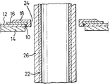
- The present invention will now be described, by way of example, with reference to the accompanying drawing in which the single Figure is a vertical section through a portion of a direct-connected cyclone system incorporating the present invention.
- The subject vent orifice forming means will allow an annular gap between a cyclone roof and an outlet tube to be made to tight tolerances from materials that will resist the erosive action of the entering dust laden vapors. The present invention can also provide for lateral and vertical movement between the outlet tube and cyclone roof which movement exceeds the width of the gap.
- As shown in the single Figure an
opening 10 is formed in acyclone roof 12 having an inner erosionresistant lining 14. The opening 10 is made larger than the required vent orifice diameter by several inches or more. Aring plate 16 is dimensioned so as to overlap the opening 10 in thecyclone roof 12. Arefractory lining 18 with appropriate anchoring system (i.e., hexmesh, s-bar, wavy V anchors, etc.) or, as an alternative, an appropriate erosion resistant ceramic material, is applied to thering plate 16 to protect those areas of the vent orifice directly exposed to the vapors and catalyst flowing at high velocity. The refractory or ceramic lining can then be cured according to the manufacturer's recommendations prior to finish grinding to the close tolerances required. - A
cyclone outlet tube 22, which forms the inner wall of thevent orifice annulus 24, is also shop fabricated and refractory or ceramic lined 26. After the refractory or ceramic is properly cured, the outer surface of the outlet tube, in the area which forms the vent orifice, is finish ground to achieve the proper tolerance. The outlet tube can later be field welded to an inlet duct (not shown) of the upper cyclone (also not shown). - Three methods are suggested for attachment of the
ring plate 16 to thecyclone roof 12. In applications where there is only a small lateral expansion, the ring plate can be attached with a seal weld around the entire outer circumference of the ring plate. If the lateral movement from expansion is greater than can be accommodated by the width of the vent orifice, the plate can be bolted to the cyclone roof with slotted bolt openings in the ring plate providing for additional movement of the plate. A third method is to have the ring plate unconnected to the cyclone roof. In this free floating arrangement the surfaces of the plate and cyclone roof are machined to a smooth finish to provide a good metal-to-metal seal. The pressure drop across the vent orifice will hold the plate in contact with the cyclone roof while still allowing the lateral movement of the plate. - The present invention provides the following specific advantages:
- 1. it allows shop fabrication and repair of the vent orifice without major field work on the cyclone bodies;
- 2. it allows the vent orifice to be constructed from materials which will resist the erosion of the high velocity gas and catalyst stream;
- 3. it allows tight tolerances to be maintained on the vent orifice surfaces;
- 4. it allows for large differential movement of the first and second stage direct-connected cyclones;
- 5. it allows cyclones to be installed without need of large expansion joints in the outlet tubes or other parts of the riser/cyclone system; and
- 6. it prevents deformation of the cyclone body due to differential thermal expansion.
- The present invention may be subject to many modifications and changes without departing from the spirit or essential characteristics thereof. The present embodiment is therefor intended in all respects to be illustrative and not restrictive of the scope of the invention.
Claims (7)
- A direct-connected cyclone system having an annular vent orifice (24), comprising:
a cyclone having a roof (12) defining an aperture (10);
characterized by:
an annular plate member (16) overlying said roof and whose opening has a circumferential wall surface with a diameter smaller than the diameter of said roof aperture (10);
an erosion protection covering (18) disposed on and adjacent at least said circumferential wall surface of said opening of the annular plate member (16); and
a cyclone outlet tube (22) extending through said opening of said annular plate member (16) and spaced therefrom to define the annular vent orifice (24) therebetween. - A cyclone system according to Claim 1 characterized in that said cyclone outlet tube (22) is externally coated with a refractory material (26).
- A cyclone system according to Claim 2 characterized in that said refractory material (26) is polished in the area adjacent said vent orifice (24).
- A cyclone system according to any one of Claims 1 to 3 characterized in that said erosion protection covering (18) comprises a ceramic material.
- A cyclone system according to any one of Claims 1 to 3 characterized in that said erosion protection covering (18) comprises a refractory material.
- A cyclone system according to any one of Claims 1 to 5 characterized by means fixedly securing said annular plate member (16) to said roof (12).
- A cyclone system according to any one of Claims 1 to 5 characterized by means securing said annular plate member (16) to said roof (12) allowing relative movement therebetween.
Applications Claiming Priority (2)
| Application Number | Priority Date | Filing Date | Title |
|---|---|---|---|
| US78469 | 1993-06-21 | ||
| US08/078,469 US5417932A (en) | 1993-06-21 | 1993-06-21 | Vent orifice in fluid catalytic cracking direct-connected cyclone apparatus |
Publications (3)
| Publication Number | Publication Date |
|---|---|
| EP0629679A2 true EP0629679A2 (en) | 1994-12-21 |
| EP0629679A3 EP0629679A3 (en) | 1995-04-12 |
| EP0629679B1 EP0629679B1 (en) | 1999-02-03 |
Family
ID=22144221
Family Applications (1)
| Application Number | Title | Priority Date | Filing Date |
|---|---|---|---|
| EP94303948A Expired - Lifetime EP0629679B1 (en) | 1993-06-21 | 1994-06-01 | Vent orifice in fluid catalytic cracking direct-connected cyclone apparatus |
Country Status (6)
| Country | Link |
|---|---|
| US (1) | US5417932A (en) |
| EP (1) | EP0629679B1 (en) |
| JP (1) | JP3390089B2 (en) |
| CA (1) | CA2124149C (en) |
| DE (1) | DE69416343T2 (en) |
| RU (1) | RU2128555C1 (en) |
Cited By (2)
| Publication number | Priority date | Publication date | Assignee | Title |
|---|---|---|---|---|
| WO2012143549A1 (en) | 2011-04-21 | 2012-10-26 | Shell Internationale Research Maatschappij B.V. | Improvements to separation of product streams |
| CN109530107A (en) * | 2018-12-03 | 2019-03-29 | 河北科技大学 | A kind of efficient, anti-coking cyclone separator |
Families Citing this family (11)
| Publication number | Priority date | Publication date | Assignee | Title |
|---|---|---|---|---|
| EP0734920A1 (en) * | 1995-03-27 | 1996-10-02 | Morton International, Inc. | An airbag inflator with components protected from high-temperature, reactive generated gases |
| DE19915888A1 (en) * | 1999-04-08 | 2000-10-19 | Zimmermann & Jansen Gmbh | Fluid catalytic cracking system and flap valve for such |
| FI114289B (en) * | 2000-04-07 | 2004-09-30 | Foster Wheeler Energia Oy | Device for separating particles from hot gases |
| EP1153662B1 (en) * | 2000-05-12 | 2004-07-14 | KHD Humboldt Wedag AG | Heat- and wear stressed mounting element, in particular segment for cyclon vortex finder |
| FR2925369B1 (en) * | 2007-12-21 | 2011-11-11 | Total France | METHOD FOR ANTI-EROSION COATING OF A WALL, ANTI-EROSION COATING AND USE THEREOF |
| US8877132B2 (en) | 2012-04-20 | 2014-11-04 | Uop Llc | Baffles for improving riser hydrodynamics |
| US9423057B2 (en) * | 2013-07-10 | 2016-08-23 | General Electric Company | Acoustical seal system |
| CN106416293B (en) | 2014-06-03 | 2021-02-26 | 杜比实验室特许公司 | Audio speaker with upward firing driver for reflected sound rendering |
| US10313793B2 (en) | 2014-06-03 | 2019-06-04 | Dolby Laboratories Licensing Corporation | Passive and active virtual height filter systems for upward firing drivers |
| US10328439B2 (en) | 2016-07-13 | 2019-06-25 | Wahl Refractory Solutions, Llc | Thimble for cyclone separator |
| US10940492B2 (en) | 2016-07-13 | 2021-03-09 | Fosbel Wahl Holdings, Llc | Thimble for cyclone separator |
Citations (3)
| Publication number | Priority date | Publication date | Assignee | Title |
|---|---|---|---|---|
| US4502947A (en) * | 1984-05-21 | 1985-03-05 | Mobil Oil Corporation | Closed cyclone FCC catalyst separation method and apparatus |
| EP0168916A1 (en) * | 1984-05-21 | 1986-01-22 | Mobil Oil Corporation | Fluidized catalytic cracking process |
| EP0488549A1 (en) * | 1990-11-30 | 1992-06-03 | Texaco Development Corporation | Catalyst separation and stripper gas removal in FCC units |
Family Cites Families (12)
| Publication number | Priority date | Publication date | Assignee | Title |
|---|---|---|---|---|
| US1265763A (en) * | 1917-03-29 | 1918-05-14 | William J Fender | Dust-collector. |
| US3064811A (en) * | 1961-05-18 | 1962-11-20 | Combustion Eng | Method and apparatus for inerting fuel separation cyclone against spontaneous combustion |
| US3273320A (en) * | 1963-07-15 | 1966-09-20 | Exxon Research Engineering Co | Cyclone separator for high temperature operations |
| US3327456A (en) * | 1964-04-30 | 1967-06-27 | Exxon Research Engineering Co | High temperature cyclone |
| US3470678A (en) * | 1967-06-20 | 1969-10-07 | Exxon Research Engineering Co | Cyclone separator for high temperature operations |
| US4125385A (en) * | 1977-08-01 | 1978-11-14 | Kerr-Mcgee Chemical Corporation | Cyclone separator for high temperature operations with corrosive gases |
| US4229194A (en) * | 1978-11-20 | 1980-10-21 | Atlantic Richfield Company | Vapor-solids separating device |
| US4357152A (en) * | 1979-07-02 | 1982-11-02 | Progressive Development, Inc. | Fluid borne particulate separator |
| US4479817A (en) * | 1980-04-03 | 1984-10-30 | Dorr-Oliver, Inc. | Pressurized hot cyclone |
| DE3228902A1 (en) * | 1982-08-03 | 1984-02-09 | Klöckner-Humboldt-Deutz AG, 5000 Köln | CYCLONE SEPARATOR |
| GB2220593B (en) * | 1988-06-09 | 1992-04-22 | Cyclofil | Hydro-cyclone |
| US5116394A (en) * | 1991-03-25 | 1992-05-26 | Foster Wheeler Energy Corporation | Cyclone separator roof |
-
1993
- 1993-06-21 US US08/078,469 patent/US5417932A/en not_active Expired - Fee Related
-
1994
- 1994-05-24 CA CA002124149A patent/CA2124149C/en not_active Expired - Lifetime
- 1994-06-01 DE DE69416343T patent/DE69416343T2/en not_active Expired - Lifetime
- 1994-06-01 EP EP94303948A patent/EP0629679B1/en not_active Expired - Lifetime
- 1994-06-09 JP JP15064594A patent/JP3390089B2/en not_active Expired - Lifetime
- 1994-06-14 RU RU94020740A patent/RU2128555C1/en active
Patent Citations (3)
| Publication number | Priority date | Publication date | Assignee | Title |
|---|---|---|---|---|
| US4502947A (en) * | 1984-05-21 | 1985-03-05 | Mobil Oil Corporation | Closed cyclone FCC catalyst separation method and apparatus |
| EP0168916A1 (en) * | 1984-05-21 | 1986-01-22 | Mobil Oil Corporation | Fluidized catalytic cracking process |
| EP0488549A1 (en) * | 1990-11-30 | 1992-06-03 | Texaco Development Corporation | Catalyst separation and stripper gas removal in FCC units |
Cited By (2)
| Publication number | Priority date | Publication date | Assignee | Title |
|---|---|---|---|---|
| WO2012143549A1 (en) | 2011-04-21 | 2012-10-26 | Shell Internationale Research Maatschappij B.V. | Improvements to separation of product streams |
| CN109530107A (en) * | 2018-12-03 | 2019-03-29 | 河北科技大学 | A kind of efficient, anti-coking cyclone separator |
Also Published As
| Publication number | Publication date |
|---|---|
| JPH0716498A (en) | 1995-01-20 |
| EP0629679B1 (en) | 1999-02-03 |
| RU2128555C1 (en) | 1999-04-10 |
| DE69416343T2 (en) | 1999-09-23 |
| CA2124149C (en) | 2005-05-03 |
| US5417932A (en) | 1995-05-23 |
| RU94020740A (en) | 1996-04-27 |
| JP3390089B2 (en) | 2003-03-24 |
| EP0629679A3 (en) | 1995-04-12 |
| CA2124149A1 (en) | 1994-12-22 |
| DE69416343D1 (en) | 1999-03-18 |
Similar Documents
| Publication | Publication Date | Title |
|---|---|---|
| EP0629679B1 (en) | Vent orifice in fluid catalytic cracking direct-connected cyclone apparatus | |
| EP0488549B1 (en) | Catalyst separation and stripper gas removal in FCC units | |
| CA1190500A (en) | Fluidized catalytic cracking | |
| US4394349A (en) | Apparatus for the fluidized catalytic cracking of hydrocarbon feedstock | |
| CA2633184C (en) | Multiple stage separator vessel | |
| US5869008A (en) | Apparatus and method for the separation and stripping of fluid catalyst cracking particles from gaseous hydrocarbons | |
| EP0262916A2 (en) | Solids-gas separator | |
| US20060096455A1 (en) | Apparatus and process for power recovery | |
| GR3036582T3 (en) | Fluid catalytic cracking of hydrocarbons with integrated apparatus for separating and stripping catalyst | |
| CA1046002A (en) | Catalyst regeneration process and apparatus | |
| US5662868A (en) | Short residence time cracking apparatus and process | |
| KR900005094B1 (en) | Fluidizing gas distribution device | |
| EP0383523B1 (en) | Trickle valve | |
| US5055177A (en) | Closed cyclone FCC catalyst separation method and apparatus | |
| EP1133538A1 (en) | Separator apparatus | |
| CA1110568A (en) | Fluid cracking process and the method for separating a suspension discharged from a riser cracking zone | |
| US5320813A (en) | Coke shield to protect vent orifice in fluid catalytic cracking direct-connected cyclone apparatus | |
| US20150283530A1 (en) | Apparatuses and risers for reacting feedstock in the presence of catalyst and methods for installing baffles in risers | |
| US5266187A (en) | Method for catalytic cracking with post-cyclone inertial separator | |
| EP0169008B1 (en) | Fcc catalyst stripping method | |
| GB2106005A (en) | Fluid catalytic cracking | |
| EP3601484B1 (en) | Vessel for removing hydrocarbons on catalyst | |
| JP3942653B2 (en) | Control method of fluidized catalytic cracking directly connected to riser cyclone | |
| WO2004007643A1 (en) | Fcc reactor comprising a sieve in the stripping zone |
Legal Events
| Date | Code | Title | Description |
|---|---|---|---|
| PUAI | Public reference made under article 153(3) epc to a published international application that has entered the european phase |
Free format text: ORIGINAL CODE: 0009012 |
|
| AK | Designated contracting states |
Kind code of ref document: A2 Designated state(s): DE FR GB IT NL |
|
| PUAL | Search report despatched |
Free format text: ORIGINAL CODE: 0009013 |
|
| AK | Designated contracting states |
Kind code of ref document: A3 Designated state(s): DE FR GB IT NL |
|
| 17P | Request for examination filed |
Effective date: 19950915 |
|
| RAP1 | Party data changed (applicant data changed or rights of an application transferred) |
Owner name: ABB LUMMUS GLOBAL INC. |
|
| GRAG | Despatch of communication of intention to grant |
Free format text: ORIGINAL CODE: EPIDOS AGRA |
|
| 17Q | First examination report despatched |
Effective date: 19980414 |
|
| GRAG | Despatch of communication of intention to grant |
Free format text: ORIGINAL CODE: EPIDOS AGRA |
|
| GRAH | Despatch of communication of intention to grant a patent |
Free format text: ORIGINAL CODE: EPIDOS IGRA |
|
| GRAH | Despatch of communication of intention to grant a patent |
Free format text: ORIGINAL CODE: EPIDOS IGRA |
|
| GRAA | (expected) grant |
Free format text: ORIGINAL CODE: 0009210 |
|
| AK | Designated contracting states |
Kind code of ref document: B1 Designated state(s): DE FR GB IT NL |
|
| PG25 | Lapsed in a contracting state [announced via postgrant information from national office to epo] |
Ref country code: FR Free format text: LAPSE BECAUSE OF FAILURE TO SUBMIT A TRANSLATION OF THE DESCRIPTION OR TO PAY THE FEE WITHIN THE PRESCRIBED TIME-LIMIT Effective date: 19990203 |
|
| REF | Corresponds to: |
Ref document number: 69416343 Country of ref document: DE Date of ref document: 19990318 |
|
| PGFP | Annual fee paid to national office [announced via postgrant information from national office to epo] |
Ref country code: FR Payment date: 19990322 Year of fee payment: 6 |
|
| ITF | It: translation for a ep patent filed |
Owner name: ING. ZINI MARANESI & C. S.R.L. |
|
| EN | Fr: translation not filed | ||
| PLBE | No opposition filed within time limit |
Free format text: ORIGINAL CODE: 0009261 |
|
| STAA | Information on the status of an ep patent application or granted ep patent |
Free format text: STATUS: NO OPPOSITION FILED WITHIN TIME LIMIT |
|
| 26N | No opposition filed | ||
| REG | Reference to a national code |
Ref country code: GB Ref legal event code: IF02 |
|
| PGFP | Annual fee paid to national office [announced via postgrant information from national office to epo] |
Ref country code: DE Payment date: 20130627 Year of fee payment: 20 Ref country code: GB Payment date: 20130627 Year of fee payment: 20 |
|
| PGFP | Annual fee paid to national office [announced via postgrant information from national office to epo] |
Ref country code: IT Payment date: 20130625 Year of fee payment: 20 |
|
| PGFP | Annual fee paid to national office [announced via postgrant information from national office to epo] |
Ref country code: NL Payment date: 20130626 Year of fee payment: 20 |
|
| REG | Reference to a national code |
Ref country code: DE Ref legal event code: R071 Ref document number: 69416343 Country of ref document: DE |
|
| REG | Reference to a national code |
Ref country code: NL Ref legal event code: V4 Effective date: 20140601 |
|
| REG | Reference to a national code |
Ref country code: GB Ref legal event code: PE20 Expiry date: 20140531 |
|
| PG25 | Lapsed in a contracting state [announced via postgrant information from national office to epo] |
Ref country code: GB Free format text: LAPSE BECAUSE OF EXPIRATION OF PROTECTION Effective date: 20140531 |
|
| PG25 | Lapsed in a contracting state [announced via postgrant information from national office to epo] |
Ref country code: DE Free format text: LAPSE BECAUSE OF EXPIRATION OF PROTECTION Effective date: 20140603 |