EP0629138B1 - Material processing - Google Patents
Material processing Download PDFInfo
- Publication number
- EP0629138B1 EP0629138B1 EP93905105A EP93905105A EP0629138B1 EP 0629138 B1 EP0629138 B1 EP 0629138B1 EP 93905105 A EP93905105 A EP 93905105A EP 93905105 A EP93905105 A EP 93905105A EP 0629138 B1 EP0629138 B1 EP 0629138B1
- Authority
- EP
- European Patent Office
- Prior art keywords
- process according
- pyrolyser
- plasma
- stream
- quenching
- Prior art date
- Legal status (The legal status is an assumption and is not a legal conclusion. Google has not performed a legal analysis and makes no representation as to the accuracy of the status listed.)
- Expired - Lifetime
Links
- 239000000463 material Substances 0.000 title claims abstract description 149
- 238000012545 processing Methods 0.000 title description 4
- 238000000034 method Methods 0.000 claims abstract description 61
- 230000008569 process Effects 0.000 claims abstract description 53
- OKTJSMMVPCPJKN-UHFFFAOYSA-N Carbon Chemical compound [C] OKTJSMMVPCPJKN-UHFFFAOYSA-N 0.000 claims abstract description 51
- 229910052799 carbon Inorganic materials 0.000 claims abstract description 48
- 238000010791 quenching Methods 0.000 claims abstract description 27
- 230000000171 quenching effect Effects 0.000 claims abstract description 24
- 238000000197 pyrolysis Methods 0.000 claims abstract description 21
- 239000007921 spray Substances 0.000 claims abstract description 19
- 231100000167 toxic agent Toxicity 0.000 claims abstract description 16
- 238000002347 injection Methods 0.000 claims abstract description 7
- 239000007924 injection Substances 0.000 claims abstract description 7
- 239000002245 particle Substances 0.000 claims description 39
- QVGXLLKOCUKJST-UHFFFAOYSA-N atomic oxygen Chemical compound [O] QVGXLLKOCUKJST-UHFFFAOYSA-N 0.000 claims description 23
- 239000001301 oxygen Substances 0.000 claims description 22
- 229910052760 oxygen Inorganic materials 0.000 claims description 22
- 230000006798 recombination Effects 0.000 claims description 17
- 238000005215 recombination Methods 0.000 claims description 17
- 239000000126 substance Substances 0.000 claims description 15
- 239000007788 liquid Substances 0.000 claims description 13
- 239000007789 gas Substances 0.000 claims description 12
- 239000007787 solid Substances 0.000 claims description 11
- XKRFYHLGVUSROY-UHFFFAOYSA-N Argon Chemical compound [Ar] XKRFYHLGVUSROY-UHFFFAOYSA-N 0.000 claims description 8
- 239000006227 byproduct Substances 0.000 claims description 8
- 238000005979 thermal decomposition reaction Methods 0.000 claims description 5
- 229910052786 argon Inorganic materials 0.000 claims description 4
- 230000004888 barrier function Effects 0.000 claims description 3
- 238000002156 mixing Methods 0.000 claims description 2
- 239000000203 mixture Substances 0.000 claims description 2
- 230000001939 inductive effect Effects 0.000 claims 3
- 238000010891 electric arc Methods 0.000 claims 2
- 229910052756 noble gas Inorganic materials 0.000 claims 1
- 230000001590 oxidative effect Effects 0.000 claims 1
- 238000001816 cooling Methods 0.000 abstract description 15
- 239000002699 waste material Substances 0.000 abstract description 14
- 230000006378 damage Effects 0.000 abstract description 9
- 150000002894 organic compounds Chemical class 0.000 description 9
- 231100000331 toxic Toxicity 0.000 description 9
- 230000002588 toxic effect Effects 0.000 description 9
- 238000006243 chemical reaction Methods 0.000 description 8
- 239000000047 product Substances 0.000 description 8
- 150000001875 compounds Chemical class 0.000 description 7
- 150000002500 ions Chemical class 0.000 description 5
- 238000007792 addition Methods 0.000 description 4
- 230000000903 blocking effect Effects 0.000 description 4
- 238000010276 construction Methods 0.000 description 4
- 150000002013 dioxins Chemical class 0.000 description 4
- 230000000694 effects Effects 0.000 description 4
- 238000001179 sorption measurement Methods 0.000 description 4
- HEMHJVSKTPXQMS-UHFFFAOYSA-M Sodium hydroxide Chemical group [OH-].[Na+] HEMHJVSKTPXQMS-UHFFFAOYSA-M 0.000 description 3
- 230000015572 biosynthetic process Effects 0.000 description 3
- 150000001722 carbon compounds Chemical class 0.000 description 3
- 238000002485 combustion reaction Methods 0.000 description 3
- 238000010494 dissociation reaction Methods 0.000 description 3
- 230000005593 dissociations Effects 0.000 description 3
- 238000004880 explosion Methods 0.000 description 3
- 238000001914 filtration Methods 0.000 description 3
- 238000004519 manufacturing process Methods 0.000 description 3
- 239000003440 toxic substance Substances 0.000 description 3
- VGVRPFIJEJYOFN-UHFFFAOYSA-N 2,3,4,6-tetrachlorophenol Chemical class OC1=C(Cl)C=C(Cl)C(Cl)=C1Cl VGVRPFIJEJYOFN-UHFFFAOYSA-N 0.000 description 2
- 230000002378 acidificating effect Effects 0.000 description 2
- 238000013459 approach Methods 0.000 description 2
- 230000002950 deficient Effects 0.000 description 2
- 238000011143 downstream manufacturing Methods 0.000 description 2
- 150000002240 furans Chemical class 0.000 description 2
- 239000003595 mist Substances 0.000 description 2
- 231100000614 poison Toxicity 0.000 description 2
- 238000000926 separation method Methods 0.000 description 2
- 239000004071 soot Substances 0.000 description 2
- 239000010891 toxic waste Substances 0.000 description 2
- XLYOFNOQVPJJNP-UHFFFAOYSA-N water Substances O XLYOFNOQVPJJNP-UHFFFAOYSA-N 0.000 description 2
- 238000010521 absorption reaction Methods 0.000 description 1
- 150000007513 acids Chemical class 0.000 description 1
- 125000001931 aliphatic group Chemical group 0.000 description 1
- 230000004075 alteration Effects 0.000 description 1
- 125000003118 aryl group Chemical group 0.000 description 1
- 238000000889 atomisation Methods 0.000 description 1
- 230000008901 benefit Effects 0.000 description 1
- 230000000711 cancerogenic effect Effects 0.000 description 1
- 231100000315 carcinogenic Toxicity 0.000 description 1
- 229910010293 ceramic material Inorganic materials 0.000 description 1
- 238000011109 contamination Methods 0.000 description 1
- 238000000354 decomposition reaction Methods 0.000 description 1
- 238000013461 design Methods 0.000 description 1
- 238000003795 desorption Methods 0.000 description 1
- 238000010586 diagram Methods 0.000 description 1
- 238000010790 dilution Methods 0.000 description 1
- 239000012895 dilution Substances 0.000 description 1
- 230000001747 exhibiting effect Effects 0.000 description 1
- 239000002360 explosive Substances 0.000 description 1
- 239000012530 fluid Substances 0.000 description 1
- 239000008246 gaseous mixture Substances 0.000 description 1
- 229910002804 graphite Inorganic materials 0.000 description 1
- 239000010439 graphite Substances 0.000 description 1
- 239000003673 groundwater Substances 0.000 description 1
- 231100001261 hazardous Toxicity 0.000 description 1
- 238000010438 heat treatment Methods 0.000 description 1
- 229930195733 hydrocarbon Natural products 0.000 description 1
- 150000002430 hydrocarbons Chemical class 0.000 description 1
- 230000002401 inhibitory effect Effects 0.000 description 1
- 230000000977 initiatory effect Effects 0.000 description 1
- 230000014759 maintenance of location Effects 0.000 description 1
- 238000012986 modification Methods 0.000 description 1
- 230000004048 modification Effects 0.000 description 1
- 238000002407 reforming Methods 0.000 description 1
- 239000000243 solution Substances 0.000 description 1
- 125000006850 spacer group Chemical group 0.000 description 1
- 231100000419 toxicity Toxicity 0.000 description 1
- 230000001988 toxicity Effects 0.000 description 1
Images



Classifications
-
- A—HUMAN NECESSITIES
- A62—LIFE-SAVING; FIRE-FIGHTING
- A62D—CHEMICAL MEANS FOR EXTINGUISHING FIRES OR FOR COMBATING OR PROTECTING AGAINST HARMFUL CHEMICAL AGENTS; CHEMICAL MATERIALS FOR USE IN BREATHING APPARATUS
- A62D3/00—Processes for making harmful chemical substances harmless or less harmful, by effecting a chemical change in the substances
- A62D3/40—Processes for making harmful chemical substances harmless or less harmful, by effecting a chemical change in the substances by heating to effect chemical change, e.g. pyrolysis
-
- A—HUMAN NECESSITIES
- A62—LIFE-SAVING; FIRE-FIGHTING
- A62D—CHEMICAL MEANS FOR EXTINGUISHING FIRES OR FOR COMBATING OR PROTECTING AGAINST HARMFUL CHEMICAL AGENTS; CHEMICAL MATERIALS FOR USE IN BREATHING APPARATUS
- A62D1/00—Fire-extinguishing compositions; Use of chemical substances in extinguishing fires
- A62D1/0028—Liquid extinguishing substances
-
- A—HUMAN NECESSITIES
- A62—LIFE-SAVING; FIRE-FIGHTING
- A62D—CHEMICAL MEANS FOR EXTINGUISHING FIRES OR FOR COMBATING OR PROTECTING AGAINST HARMFUL CHEMICAL AGENTS; CHEMICAL MATERIALS FOR USE IN BREATHING APPARATUS
- A62D3/00—Processes for making harmful chemical substances harmless or less harmful, by effecting a chemical change in the substances
- A62D3/10—Processes for making harmful chemical substances harmless or less harmful, by effecting a chemical change in the substances by subjecting to electric or wave energy or particle or ionizing radiation
- A62D3/19—Processes for making harmful chemical substances harmless or less harmful, by effecting a chemical change in the substances by subjecting to electric or wave energy or particle or ionizing radiation to plasma
-
- C—CHEMISTRY; METALLURGY
- C10—PETROLEUM, GAS OR COKE INDUSTRIES; TECHNICAL GASES CONTAINING CARBON MONOXIDE; FUELS; LUBRICANTS; PEAT
- C10B—DESTRUCTIVE DISTILLATION OF CARBONACEOUS MATERIALS FOR PRODUCTION OF GAS, COKE, TAR, OR SIMILAR MATERIALS
- C10B19/00—Heating of coke ovens by electrical means
-
- C—CHEMISTRY; METALLURGY
- C10—PETROLEUM, GAS OR COKE INDUSTRIES; TECHNICAL GASES CONTAINING CARBON MONOXIDE; FUELS; LUBRICANTS; PEAT
- C10B—DESTRUCTIVE DISTILLATION OF CARBONACEOUS MATERIALS FOR PRODUCTION OF GAS, COKE, TAR, OR SIMILAR MATERIALS
- C10B39/00—Cooling or quenching coke
- C10B39/04—Wet quenching
-
- C—CHEMISTRY; METALLURGY
- C10—PETROLEUM, GAS OR COKE INDUSTRIES; TECHNICAL GASES CONTAINING CARBON MONOXIDE; FUELS; LUBRICANTS; PEAT
- C10B—DESTRUCTIVE DISTILLATION OF CARBONACEOUS MATERIALS FOR PRODUCTION OF GAS, COKE, TAR, OR SIMILAR MATERIALS
- C10B53/00—Destructive distillation, specially adapted for particular solid raw materials or solid raw materials in special form
-
- A—HUMAN NECESSITIES
- A62—LIFE-SAVING; FIRE-FIGHTING
- A62D—CHEMICAL MEANS FOR EXTINGUISHING FIRES OR FOR COMBATING OR PROTECTING AGAINST HARMFUL CHEMICAL AGENTS; CHEMICAL MATERIALS FOR USE IN BREATHING APPARATUS
- A62D2101/00—Harmful chemical substances made harmless, or less harmful, by effecting chemical change
- A62D2101/20—Organic substances
- A62D2101/22—Organic substances containing halogen
-
- A—HUMAN NECESSITIES
- A62—LIFE-SAVING; FIRE-FIGHTING
- A62D—CHEMICAL MEANS FOR EXTINGUISHING FIRES OR FOR COMBATING OR PROTECTING AGAINST HARMFUL CHEMICAL AGENTS; CHEMICAL MATERIALS FOR USE IN BREATHING APPARATUS
- A62D2101/00—Harmful chemical substances made harmless, or less harmful, by effecting chemical change
- A62D2101/20—Organic substances
- A62D2101/28—Organic substances containing oxygen, sulfur, selenium or tellurium, i.e. chalcogen
-
- A—HUMAN NECESSITIES
- A62—LIFE-SAVING; FIRE-FIGHTING
- A62D—CHEMICAL MEANS FOR EXTINGUISHING FIRES OR FOR COMBATING OR PROTECTING AGAINST HARMFUL CHEMICAL AGENTS; CHEMICAL MATERIALS FOR USE IN BREATHING APPARATUS
- A62D2203/00—Aspects of processes for making harmful chemical substances harmless, or less harmful, by effecting chemical change in the substances
- A62D2203/04—Combined processes involving two or more non-distinct steps covered by groups A62D3/10 - A62D3/40
-
- A—HUMAN NECESSITIES
- A62—LIFE-SAVING; FIRE-FIGHTING
- A62D—CHEMICAL MEANS FOR EXTINGUISHING FIRES OR FOR COMBATING OR PROTECTING AGAINST HARMFUL CHEMICAL AGENTS; CHEMICAL MATERIALS FOR USE IN BREATHING APPARATUS
- A62D2203/00—Aspects of processes for making harmful chemical substances harmless, or less harmful, by effecting chemical change in the substances
- A62D2203/10—Apparatus specially adapted for treating harmful chemical agents; Details thereof
Definitions
- This invention relates to thermal decomposition processes such as the destruction of toxic waste matter, and is concerned with both a process and apparatus. It will be convenient to hereinafter particularly describe the invention with reference to the example application to destruction of waste matter.
- This invention relates particularly but not exclusively to treatment of waste products resulting from chemical treatment, chemical conversion and the like.
- These products often contain highly toxic directly physiologically active or carcinogenic substances.
- such products can include per- or polychlorinated and per- or polyfluorinated aliphatic or aromatic substances such as chlorophenols, dioxins and furans. In addition to their toxicity, these compounds often exhibit high chemical and thermal resistance.
- Waste matter destruction is becoming a problem of great magnitude throughout the world.
- Two methods of removing contaminated material have become established, namely land fill and high temperature combustion techniques.
- the generally attainable temperatures for example up to 1500°C, are insufficient to destroy all the toxic substances.
- the most thermally stable harmful substances are thus delivered into the atmosphere.
- the combustion process can promote the formation of additional dioxins and furans which are then also delivered into the atmosphere.
- US-A-4644877 discloses a pyrolytic waste destruction system in which waste material is fed to a plasma burner and exits via cylindrical member into a reaction vessel forming a reaction chamber. Waste products exit chamber via outlet openings for quenching in spray ring. The exit chamber is for cooling the pyrolysed waste material to form recombined products.
- a thermal decomposition process includes the steps of forming a plasma within a pyrolyser, injecting material to be treated as a fine spray and/or a gas into said plasma, moving said material as a stream through said pyrolyser in a direction towards an exit end of the pyrolyser, maintaining said material at a high temperature during said material stream movement so that substantially complete pyrolysis of said material is achieved and recombination of unwanted by-products is substantially prevented, moving said material stream through said exit end at a temperature above that at which said recombination will occur, and subjecting said material stream to rapid quenching at or adjacent said exit end and before the temperature of that material stream falls to a level at which recombination to said unwanted by-products will occur.
- the quenched material is subjected to an environment in which residual toxic compounds are adsorbed on a solid carrier substance so as to be thereby capable of separation from the main body of the material.
- a solid carrier substance is particulate carbon, and it is further preferred that the carbon is formed by the treatment of the waste material in the pyrolyser.
- the material to be treated may be in the form of a liquid which is atomised on introduction to the pyrolyser.
- the material may be in a particulate solid form or in the form of a gas.
- the pyrolyser includes a high energy electrothermal plasma into which the atomised material is injected so as to result in dissociation of the molecules of which the material is composed.
- the speed at which such dissociation occurs is governed, at least in part, by the temperature of the plasma.
- the material emerges from the plasma arc as a stream which passes through a hot zone within which the temperature of the material is maintained at a sufficiently high level to encourage continuation of the pyrolysis which is commenced within the plasma. That may be achieved in a number of ways as hereinafter described. Residence time within the hot zone may be determined as appropriate to increase the probability that there is complete dissociation of all molecules within the material stream. The longer the time for which a particular material is subjected to heating, the greater the likelihood of decomposing compounds exhibiting high thermal resistance. Generally the higher the temperature, the greater will be the speed at which decomposition is accomplished.
- the material stream is cooled by being subjected to rapid quenching in a cooling zone after leaving the hot zone, and the speed of quenching is preferably such as to prevent, or at least minimise, recombination of the dissociated ions.
- Residual toxic compounds which are separated from the material stream by absorption or adsorbtion on particulate carbon as previously described, may be destroyed by subjecting the particulate carbon to appropriate further treatment.
- the aforementioned hot zone is defined by a tube (hereinafter called the flight tube) through which the material stream travels between the plasma arc and the cooling zone.
- the material stream preferably enters that tube immediately upon emerging from the plasma arc.
- the dimensions and construction of the flight tube can have an influence on the efficiency of the process as hereinafter discussed.
- the pyrolysis of material such as waste material may result in production of carbon particles as soot or activated carbon, and those particles could influence downstream processing of the material.
- the particles could block or partially block the flight tube. This will especially be the case where the material to be treated comprises mainly hydrocarbons.
- the material comprises mainly oxygen containing organic compounds, there may not be a problem with excessive carbon particles.
- oxygen is introduced into the plasma so as to react with carbon particles as may be formed, and thereby produce gaseous carbon compounds with the concomitant evolution of heat.
- Such addition of oxygen may therefore lower the level of solid carbon within the material stream so as to more easily facilitate downstream processing of that material for example, facilitate passage of the material stream through the flight tube.
- the liberated heat assists in maintaining the temperature of the material stream suitably high as it passes through the flight tube to resist recombination to form toxic compounds.
- the need to convert solid carbon to gaseous carbon compounds by addition of oxygen to the process material may be eliminated, or at least reduced, by the dilution of the material to be processed in an inert carrier liquid which passes through the apparatus without affecting the reaction dynamics.
- the carrier liquid will have the effect of lowering the percentage by weight of carbon particles in the stream issuing from the plasma.
- the amount of inert carrier liquid added will be controlled to reduce the percentage by weight of carbon particles to a level that avoids blockages of equipment without the addition of any oxygen.
- the level of carbon particles in the material stream issuing from the flight tube may be such as to cause blocking or partially blocking at the cooling zone and/or at some other part of the apparatus following the cooling zone, and that may occur notwithstanding the introduction of oxygen into the plasma as described above.
- further oxygen is added to the stream issuing from the flight tube so as to react with the carbon particles and lower the level of particles within the material stream.
- the reaction of the oxygen with the carbon is exothermic which assists in maintaining the temperature of the material stream suitably high until actual quenching of the stream takes place.
- the high temperatures tend to resist recombination of ions to form toxic compounds. It is preferred that a sharp temperature gradient be effectively provided at the cooling zone.
- the cooled material may be exposed to an alkaline environment for encouraging the adsorption of any acidic residual toxic compounds on the carrier substance, for example carbon particles.
- toxic compounds which escape pyrolysis, or which are formed by recombination following pyrolysis can be isolated on the carbon particles, and those particles may be separated from the remainder of the processed material by any suitable means. By way of example, that separation may be achieved through filtration.
- the separated carbon particles, with toxic compounds adsorbed thereon, may be subjected to further treatment to decompose the toxic compounds.
- the particles may be subjected to further treatment which leads to the toxic compounds being desorbed into a liquid which is then recirculated through the process.
- the carbon particles may be disposed of by landfill.
- the procedure adopted in any circumstance will generally depend on the level of toxic compounds on the carbon particles.
- a thermal decomposition apparatus includes a pyrolyser having means for generating a plasma arc and passage means for containing plasma beyond the region of said arc, material introducing means located at or adjacent the region of said arc and being operative to introduce material into said pyrolyser as a fine spray and/or as a gas, and quenching means located at or adjacent an exit end of said pyrolyser, wherein said pyrolyser is operative to maintain said introduced material at a high temperature so that substantially complete pyrolysis of said material is achieved and recombination of unwanted by-products is substantially prevented during movement of said material through said passage means to the exit end of said pyrolyser and said quenching means is operative rapidly to quench said material emerging from said exit end before the temperature of that emerging material falls to a level at which recombination to said unwanted by-products will occur, and wherein said passage means provides for control of a boundary layer of said material for ensuring a
- the line 1 represents the path of the material to be treated as it is introduced into the pyrolyser 2.
- the material may be introduced into the pyrolyser 2 in any suitable form, but it is preferred that it be in the form of a fine spray of liquid and/or solid particles, or a gas, or a combination of such a fine spray and a gas. It is further preferred that the material be injected into the pyrolyser 2 under pressure.
- the stream of liquid may be atomised at or immediately preceding the point of injection into the pyrolyser 2, and any suitable nozzle or other means may be used for that purpose.
- the liquid droplets resulting from the atomisation have a diameter of 100 micrometer or less.
- the liquid droplets need to be sufficiently small to enable complete pyrolysis. If they are too large, the surface of the droplets may merely char under the conditions existing within the pyrolyser 2.
- each of those particles is preferably of a suitably small size for the reason given above.
- a particle size of 100 micrometer or less will generally be satisfactory.
- the pyrolyser 2 includes means 3 for generating a plasma arc 4 so as to enable production of a high energy electrothermal plasma.
- the pyrolyser 2 also includes a hot zone 6 immediately following the arc generating means 3 and which receives the material stream 5 emerging from the arc generating means 3.
- the plasma gas 7 is argon or an argon mixture as that produces an inert plasma atmosphere in which the pyrolysis takes place.
- the arc generating means 3 may, for example, be a plasma torch the same as or similar to that disclosed by PCT Patent Application AU89/00396.
- the temperature within the plasma may typically be in the region 10,000°C to 15,000°C.
- other types of plasma such as a steam plasma may also be used.
- the direction in which the material to be treated is introduced into the plasma arc 4 may be selected according to preference or circumstances.
- the direction may be generally parallel to the line of the arc 4, or generally transverse thereto, but the later is usually preferred.
- the region of the pyrolyser 2 at which the material to be treated is introduced into the plasma is maintained at a suitably high temperature, for example, a temperature of 1,000°C or preferably higher.
- the material may be injected directly into the core of the plasma arc 4, or at least close to the downstream attachment 8 of the arc 4. If direct injection is not possible, the surfaces of the torch 3 in the region of material introduction may be heated to maintain a temperature of a suitably high level.
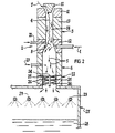
- FIG 2 provides a clearer indication of the preferred location of the point 9 at which material to be treated is introduced into the pyrolyser 2.
- the particular torch 3 which is shown in Figure 2, and which forms part of the pyrolyser 2, includes a cathode 10 and two anodes 11 and 12 separated by a bank 13 of spacers.
- the anode 11 functions as a start-up anode for initiating the arc 4, and once generated the arc 4 is then extended so that its downstream attachment 8 is at the anode 12.
- Other forms of torches could be adopted.
- material to be treated is injected into the torch passage 14 at or adjacent the location of the arc attachment 8.
- the direction of that injection is generally transverse to the longitudinal axis of the passage 14 as that facilitates injection into the core of the arc 4.
- the molecules which make-up the injected material are caused to dissociate under the influence of the high temperatures prevailing within the plasma, and the material thereby undergoes pyrolysis, or at least substantial pyrolysis.
- the material emerges from the plasma arc 4 as a stream 5 which is directed into and through the hot zone 6.
- the stream of material 5 is primarily a gas having associated therewith particles of solid carbon in the form of soot.
- the hot zone 6 is formed by an elongate hollow tube which will be hereinafter referred to as the flight tube.
- the tube 6 in effect forms an extension or continuation of the torch passage 14, and the dimensions of the tube 6 will be selected to suit particular requirements and circumstances. It is a basic function of the tube 6 to provide containment of the material stream 5 in an environment which promotes continuation of the pyrolysis process. That is, it may happen that pyrolysis of the material is not completed within the torch 3, and the function of the tube 6 is to provide an extension of the environment within which pyrolysis takes place.
- the tube 6 extends the residence time of the material within an appropriate high temperature environment and thereby optimises the possibility that complete pyrolysis will be achieved.
- the flight tube is slender and has a diameter to length ratio of about 2 in 25.
- the length of the tube may be selected so as to achieve a suitable residence time of the processed material within the tube and any suitable diameter to length ratio may be adopted. The nature of the toxic compounds within the material to be treated will influence the determination of an appropriate residence time within the tube 6.
- the temperature of the stream 5 entering the tube 6 may be above 3,500°C and the temperature of the stream exiting the tube 6 may be 1,200°C, or thereabouts.
- the fluid flow boundary layer of the material stream which contacts the surrounding surface of the tube 6 will tend to cool because of that contact.
- the tube 6 may be designed in such a way as to enable control of the boundary layer so that it is kept as thin as possible.
- it is desirable that the temperature of the material stream is substantially consistent throughout that stream as it emerges from the exit end 15 of the pyrolyser 2.
- FIG. 3 One approach to the foregoing is shown diagrammatically in Figure 3.
- the inner surface of the flight tube 6 shown in Figure 3 is provided with a series of lips 16 which tend to deflect the boundary layer of the material stream 5 back towards the axial center of that stream.
- the resulting turbulence inhibits the formation of a distinct cool boundary layer, and there is continual mixing of the boundary layer with the inner relatively hot body of the material stream such that a substantially consistent temperature is maintained across the width of the stream.
- Figure 4 illustrates another approach in which the tube 6 has a lining 17 which is capable of withstanding high temperatures, and particularly temperatures above 1,000°C.
- the lining 17 may be composed of a ceramic material. If desired, such an arrangement may be modified by introducing an external source of heat to the lining 17 at an appropriate location, such as adjacent to the exit end 15 of the pyrolyser 2.
- the body 18 of the tube 6 which surrounds the lining 17 may be cooled by water (for example) entering at the inlet 19 and exiting at the outlet 20. Similar cooling may be desirable in other forms of the tube 6, including that shown in Figure 3.
- the material stream 5 issuing from the torch 3 will contain carbon particles. If the level of carbon particles is relatively high, there may be a danger of the carbon blocking the tube 6.
- a stream of oxygen may be fed into the pyrolyser 2 for converting some of the carbon particles to gaseous carbon compounds.
- the oxygen is fed into the torch 3 at a location 21 adjacent the point 9 at which the material to be treated is introduced. Other arrangements are clearly possible.
- the tube 6 may include a graphite lining.
- it may be important to control the stream of oxygen entering at 21, so as to maintain an oxygen deficient atmosphere within the tube 6.
- the ratio of oxygen to carbon may be maintained at 30% below stoichiometric levels. If such an atmosphere is not maintained some oxygen may react with the carbon of the tube lining, thereby eating away the lining.
- An oxygen deficient atmosphere will also tend to reduce the combination of dissociated ions to form undesirable oxygen containing compounds.
- the material stream 5 passing out of the exit end 15 of the pyrolyser 2 is subjected to quenching in a cooling zone 22.
- the material is then, and/or subsequently, subjected to an environment as hereinafter described in which residual toxic organic compounds are adsorbed on a particulate carrier.
- the carrier substance may be provided by the unreacted carbon particles remaining within the material stream 5.
- the level of carbon particles in the material stream 5 passing out of the exit end 15 may, for example, be 1% by weight, or greater. Such a level of carbon may cause clogging or blocking of components of the processing apparatus which follow the pyrolyser 2. Consequently, in some circumstances it may be desirable to further reduce the carbon content by the introduction of a further stream 23 of oxygen to convert some of the remaining carbon particles to gaseous carbon products.
- the carbon content of the material stream entering the cooling zone 22 is in the order of 0.5% by weight.
- the introduction of the further oxygen stream 23 may have another effect. That is, the heat generated by the reaction of that oxygen with carbon may assist in maintaining the material stream 5 at a suitably high temperature right up until actual quenching takes place.
- the temperature of the material stream 5 just prior to quenching be at least 1,500°C, and it is preferred that the temperature be in order of 1,800°C to 2,000°C.
- the higher temperatures resist recombination of dissociated ions to form toxic compounds, for example dioxins.
- the cooling zone 22 includes a bank of sprays 24 arranged to produce a cool barrier 25 through which the material stream 5 must pass. That is, the stream 5 is confined to a passage 26 which is completely filled at the location of the sprays 24 by the barrier 25.
- the arrangement is such that quenching of the material stream is complete, and that as a result there is a very sudden sharp drop in the temperature of the material.
- the passage 26 is formed as an extension of the passage through the tube 6.
- the cooled material issuing from the cooling zone 22 may be passed into and through a scrubber 27 as shown.
- the pH of the scrubber 27 will generally be alkaline for removing acidic compounds from the material received.
- the carbon particles within that material may be dispersed within a body 28 of the alkaline scrubber liquor so that acidic organic compounds are encouraged to be adsorbed on the carbon particles.
- the optimum process parameters such as pH and temperature of the scrubber, liquor which are required to achieve maximum toxic organic compound adsorption, may be determined by routine experimentation.
- the scrubber liquor is a sodium hydroxide solution, but other types of liquor may be used.
- the same liquor may be used in the quench sprays 24 and the scrubber sprays 29.
- a pump 30 may operate to draw liquor from the liquor body 28 to feed the sprays 24 and 29.
- the line 31 in Figure 1 represents the supply of liquor to the scrubber 27, and the line 32 represents the withdrawal of spent liquor from the scrubber 27.
- the carbon particles may be separated from the scrubber liquor by means of a simple filtration process, which is indicated in Figure 1 by the block 33. That filtration may be carried out on a continuous basis or on a batch basis.
- the toxic organic compounds adsorbed on the carbon particles may be separated from the carbon particles by a desorption process which is represented by the block 34 in Figure 1. That is, the adsorption process effected in the scrubber 27 is reversed.
- the compounds are typically desorbed in water which can be recycled through the process as part of the material input 1.
- the scrubber 27 has a rectangular configuration and is substantially larger than the tube which forms the cooling zone 22.
- a plurality of scrubber sprays 29 are located in the operatively upper region of the scrubber 27 for directing scrubber liquor as a fine spray or mist. The direction of that spray or mist is preferably downwards.
- the apparatus may include an explosion vent 35 as shown in Figure 5, to vent the system in the event of the build-up of an explosive gaseous mixture. This is an important safety feature to reduce the danger of explosion.
- the explosion vent is of known form and construction. In the example shown, the vent 35 is located adjacent the scrubber 27.
- the material which has remained in the gaseous form and which has not been scrubbed from the gas in the scrubber 27, may be passed to atmosphere by way of a stack 36 shown in Figure 5.
- the stack 36 may, for example, include a number of stack sprays 37 which operate to remove any remaining traces of gaseous compounds having an affinity for an aqueous alkaline environment.
- the stack sprays 37 are supplied with liquor by way of the pump 30.
- the pyrolyser 2 specifically, and the entire apparatus more generally, forms a very compact unit which lends itself to on-site use.
- the apparatus can be integrated into an existing process so that there is no nett production of toxic waste. This is a major advantage as the transportation of toxic substances is hazardous.
- a unique characteristic of the process described is the deliberate retention of particulate carbon within the stream of material and the control of the process conditions such that the carbon particles act as a carrier substance for toxic organic compounds which have survived the pyrolysis phase of the process. That is, the organic compounds which survived the processing steps preceding the quenching process, are effectively captured by attachment or adsorption on the carbon particles. The surviving organic compounds are thereby captured in a manner which facilitates convenient disposal or alternatively subsequent processing as considered appropriate, depending on the level of toxic organic compounds. That is contrary to the accepted practice of inhibiting carbon formation in existing toxic compound destruction processes.
- a process according to the invention is useful for the effective destruction of a wide variety of toxic products, including chlorophenols and dioxins. The process is robust and safe.
Landscapes
- Chemical & Material Sciences (AREA)
- Engineering & Computer Science (AREA)
- Oil, Petroleum & Natural Gas (AREA)
- Chemical Kinetics & Catalysis (AREA)
- General Chemical & Material Sciences (AREA)
- Business, Economics & Management (AREA)
- Emergency Management (AREA)
- Organic Chemistry (AREA)
- Materials Engineering (AREA)
- General Health & Medical Sciences (AREA)
- Toxicology (AREA)
- Health & Medical Sciences (AREA)
- Plasma & Fusion (AREA)
- Physics & Mathematics (AREA)
- Treating Waste Gases (AREA)
- Processing Of Solid Wastes (AREA)
- Chemical Or Physical Treatment Of Fibers (AREA)
- Physical Or Chemical Processes And Apparatus (AREA)
- Electrical Discharge Machining, Electrochemical Machining, And Combined Machining (AREA)
- Developing Agents For Electrophotography (AREA)
- Gasification And Melting Of Waste (AREA)
Abstract
Description
- This invention relates to thermal decomposition processes such as the destruction of toxic waste matter, and is concerned with both a process and apparatus. It will be convenient to hereinafter particularly describe the invention with reference to the example application to destruction of waste matter.
- This invention relates particularly but not exclusively to treatment of waste products resulting from chemical treatment, chemical conversion and the like. These products often contain highly toxic directly physiologically active or carcinogenic substances. By way of example, such products can include per- or polychlorinated and per- or polyfluorinated aliphatic or aromatic substances such as chlorophenols, dioxins and furans. In addition to their toxicity, these compounds often exhibit high chemical and thermal resistance.
- Waste matter destruction is becoming a problem of great magnitude throughout the world. Two methods of removing contaminated material have become established, namely land fill and high temperature combustion techniques.
- In the land fill technique, which generally only applies to solids, the toxic matter is not destroyed, but is simply stored in dumps. At best the dumps are designed to prevent contamination of ground water by waste matter deposited therein. This technique is not suited to some areas, for example, areas in which there is an ongoing danger of leakage, seepage or the like.
- In the high temperature combustion technique, the generally attainable temperatures, for example up to 1500°C, are insufficient to destroy all the toxic substances. The most thermally stable harmful substances are thus delivered into the atmosphere. Further the combustion process can promote the formation of additional dioxins and furans which are then also delivered into the atmosphere.
- Thus there are disadvantages associated with each of the techniques described above.
- US-A-4644877 discloses a pyrolytic waste destruction system in which waste material is fed to a plasma burner and exits via cylindrical member into a reaction vessel forming a reaction chamber. Waste products exit chamber via outlet openings for quenching in spray ring. The exit chamber is for cooling the pyrolysed waste material to form recombined products.
- According to a first aspect of this invention a thermal decomposition process includes the steps of forming a plasma within a pyrolyser, injecting material to be treated as a fine spray and/or a gas into said plasma, moving said material as a stream through said pyrolyser in a direction towards an exit end of the pyrolyser, maintaining said material at a high temperature during said material stream movement so that substantially complete pyrolysis of said material is achieved and recombination of unwanted by-products is substantially prevented, moving said material stream through said exit end at a temperature above that at which said recombination will occur, and subjecting said material stream to rapid quenching at or adjacent said exit end and before the temperature of that material stream falls to a level at which recombination to said unwanted by-products will occur.
- In one form of the process, the quenched material is subjected to an environment in which residual toxic compounds are adsorbed on a solid carrier substance so as to be thereby capable of separation from the main body of the material. It is preferred that the solid carrier substance referred to above is particulate carbon, and it is further preferred that the carbon is formed by the treatment of the waste material in the pyrolyser.
- The material to be treated may be in the form of a liquid which is atomised on introduction to the pyrolyser. Alternatively, the material may be in a particulate solid form or in the form of a gas.
- It is preferred that the pyrolyser includes a high energy electrothermal plasma into which the atomised material is injected so as to result in dissociation of the molecules of which the material is composed. The speed at which such dissociation occurs is governed, at least in part, by the temperature of the plasma. It is further preferred that the material emerges from the plasma arc as a stream which passes through a hot zone within which the temperature of the material is maintained at a sufficiently high level to encourage continuation of the pyrolysis which is commenced within the plasma. That may be achieved in a number of ways as hereinafter described. Residence time within the hot zone may be determined as appropriate to increase the probability that there is complete dissociation of all molecules within the material stream. The longer the time for which a particular material is subjected to heating, the greater the likelihood of decomposing compounds exhibiting high thermal resistance. Generally the higher the temperature, the greater will be the speed at which decomposition is accomplished.
- The material stream is cooled by being subjected to rapid quenching in a cooling zone after leaving the hot zone, and the speed of quenching is preferably such as to prevent, or at least minimise, recombination of the dissociated ions.
- Residual toxic compounds which are separated from the material stream by absorption or adsorbtion on particulate carbon as previously described, may be destroyed by subjecting the particulate carbon to appropriate further treatment.
- In a preferred form of the process, the aforementioned hot zone is defined by a tube (hereinafter called the flight tube) through which the material stream travels between the plasma arc and the cooling zone. The material stream preferably enters that tube immediately upon emerging from the plasma arc. The dimensions and construction of the flight tube can have an influence on the efficiency of the process as hereinafter discussed.
- As described above, the pyrolysis of material such as waste material may result in production of carbon particles as soot or activated carbon, and those particles could influence downstream processing of the material. For example, the particles could block or partially block the flight tube. This will especially be the case where the material to be treated comprises mainly hydrocarbons. However where the material comprises mainly oxygen containing organic compounds, there may not be a problem with excessive carbon particles.
- In one form of the process, oxygen is introduced into the plasma so as to react with carbon particles as may be formed, and thereby produce gaseous carbon compounds with the concomitant evolution of heat. Such addition of oxygen may therefore lower the level of solid carbon within the material stream so as to more easily facilitate downstream processing of that material for example, facilitate passage of the material stream through the flight tube. Furthermore, the liberated heat assists in maintaining the temperature of the material stream suitably high as it passes through the flight tube to resist recombination to form toxic compounds.
- The need to convert solid carbon to gaseous carbon compounds by addition of oxygen to the process material may be eliminated, or at least reduced, by the dilution of the material to be processed in an inert carrier liquid which passes through the apparatus without affecting the reaction dynamics. The carrier liquid will have the effect of lowering the percentage by weight of carbon particles in the stream issuing from the plasma. Ideally the amount of inert carrier liquid added will be controlled to reduce the percentage by weight of carbon particles to a level that avoids blockages of equipment without the addition of any oxygen.
- In some circumstances, the level of carbon particles in the material stream issuing from the flight tube may be such as to cause blocking or partially blocking at the cooling zone and/or at some other part of the apparatus following the cooling zone, and that may occur notwithstanding the introduction of oxygen into the plasma as described above. To overcome that problem, in one form of the process, further oxygen is added to the stream issuing from the flight tube so as to react with the carbon particles and lower the level of particles within the material stream. The reaction of the oxygen with the carbon is exothermic which assists in maintaining the temperature of the material stream suitably high until actual quenching of the stream takes place. The high temperatures tend to resist recombination of ions to form toxic compounds. It is preferred that a sharp temperature gradient be effectively provided at the cooling zone.
- The cooled material may be exposed to an alkaline environment for encouraging the adsorption of any acidic residual toxic compounds on the carrier substance, for example carbon particles. Thus, toxic compounds which escape pyrolysis, or which are formed by recombination following pyrolysis, can be isolated on the carbon particles, and those particles may be separated from the remainder of the processed material by any suitable means. By way of example, that separation may be achieved through filtration.
- The separated carbon particles, with toxic compounds adsorbed thereon, may be subjected to further treatment to decompose the toxic compounds. For example, the particles may be subjected to further treatment which leads to the toxic compounds being desorbed into a liquid which is then recirculated through the process.
- Alternatively, the carbon particles may be disposed of by landfill. The procedure adopted in any circumstance will generally depend on the level of toxic compounds on the carbon particles.
- According to a second aspect of this invention a thermal decomposition apparatus includes a pyrolyser having means for generating a plasma arc and passage means for containing plasma beyond the region of said arc, material introducing means located at or adjacent the region of said arc and being operative to introduce material into said pyrolyser as a fine spray and/or as a gas, and quenching means located at or adjacent an exit end of said pyrolyser, wherein said pyrolyser is operative to maintain said introduced material at a high temperature so that substantially complete pyrolysis of said material is achieved and recombination of unwanted by-products is substantially prevented during movement of said material through said passage means to the exit end of said pyrolyser and said quenching means is operative rapidly to quench said material emerging from said exit end before the temperature of that emerging material falls to a level at which recombination to said unwanted by-products will occur, and wherein said passage means provides for control of a boundary layer of said material for ensuring a substantially consistent temperature for the material across said passage means.
- Embodiments of the invention are described in detail in the following passages of the specification which refer to the accompanying drawings. The drawings, however, are merely illustrative of how the invention might be put into effect, so that the specific form and arrangement of the various features as shown is not to be understood as limiting on the invention.
- In the drawings:
- Figure 1 is a flow diagram representing one form of the process according to the invention.
- Figure 2 is a diagrammatic sectional view through one form of pyrolyser for use in a process as represented by Figure 1.
- Figure 3 is a semi-diagrammatic cross-sectional view of one form of flight tube suitable for use in the apparatus shown by Figure 2.
- Figure 4 is a semi-daigrammatic cross-sectional view of another form of flight tube suitable for use in the apparatus of Figure 2.
- Figure 5 is a diagrammatic view of apparatus in accordance with one embodiment of the invention.
-
- In Figure 1 the line 1 represents the path of the material to be treated as it is introduced into the
pyrolyser 2. The material may be introduced into thepyrolyser 2 in any suitable form, but it is preferred that it be in the form of a fine spray of liquid and/or solid particles, or a gas, or a combination of such a fine spray and a gas. It is further preferred that the material be injected into thepyrolyser 2 under pressure. - In the event that the material is moved along the path 1 as a stream of liquid, the stream of liquid may be atomised at or immediately preceding the point of injection into the
pyrolyser 2, and any suitable nozzle or other means may be used for that purpose. Preferably, the liquid droplets resulting from the atomisation have a diameter of 100 micrometer or less. In particular, the liquid droplets need to be sufficiently small to enable complete pyrolysis. If they are too large, the surface of the droplets may merely char under the conditions existing within thepyrolyser 2. - If the material entering the
pyrolyser 2 is in the form of or includes a spray of solid particles, each of those particles is preferably of a suitably small size for the reason given above. A particle size of 100 micrometer or less will generally be satisfactory. - The
pyrolyser 2 includesmeans 3 for generating aplasma arc 4 so as to enable production of a high energy electrothermal plasma. Thepyrolyser 2 also includes ahot zone 6 immediately following the arc generating means 3 and which receives thematerial stream 5 emerging from the arc generating means 3. - It is preferred that the plasma gas 7 is argon or an argon mixture as that produces an inert plasma atmosphere in which the pyrolysis takes place. The arc generating means 3 may, for example, be a plasma torch the same as or similar to that disclosed by PCT Patent Application AU89/00396. In that regard, the temperature within the plasma may typically be in the region 10,000°C to 15,000°C. Alternatively, other types of plasma such as a steam plasma may also be used.
- The direction in which the material to be treated is introduced into the
plasma arc 4 may be selected according to preference or circumstances. By way of example, the direction may be generally parallel to the line of thearc 4, or generally transverse thereto, but the later is usually preferred. - It is preferred that the region of the
pyrolyser 2 at which the material to be treated is introduced into the plasma, is maintained at a suitably high temperature, for example, a temperature of 1,000°C or preferably higher. The material may be injected directly into the core of theplasma arc 4, or at least close to thedownstream attachment 8 of thearc 4. If direct injection is not possible, the surfaces of thetorch 3 in the region of material introduction may be heated to maintain a temperature of a suitably high level. - Figure 2 provides a clearer indication of the preferred location of the point 9 at which material to be treated is introduced into the
pyrolyser 2. Theparticular torch 3 which is shown in Figure 2, and which forms part of thepyrolyser 2, includes acathode 10 and twoanodes 11 and 12 separated by abank 13 of spacers. The anode 11 functions as a start-up anode for initiating thearc 4, and once generated thearc 4 is then extended so that itsdownstream attachment 8 is at theanode 12. Other forms of torches could be adopted. - In the particular arrangement shown in Figure 2, material to be treated is injected into the
torch passage 14 at or adjacent the location of thearc attachment 8. The direction of that injection is generally transverse to the longitudinal axis of thepassage 14 as that facilitates injection into the core of thearc 4. - The molecules which make-up the injected material are caused to dissociate under the influence of the high temperatures prevailing within the plasma, and the material thereby undergoes pyrolysis, or at least substantial pyrolysis. The material emerges from the
plasma arc 4 as astream 5 which is directed into and through thehot zone 6. The stream ofmaterial 5 is primarily a gas having associated therewith particles of solid carbon in the form of soot. - In the particular arrangement shown, the
hot zone 6 is formed by an elongate hollow tube which will be hereinafter referred to as the flight tube. Thetube 6 in effect forms an extension or continuation of thetorch passage 14, and the dimensions of thetube 6 will be selected to suit particular requirements and circumstances. It is a basic function of thetube 6 to provide containment of thematerial stream 5 in an environment which promotes continuation of the pyrolysis process. That is, it may happen that pyrolysis of the material is not completed within thetorch 3, and the function of thetube 6 is to provide an extension of the environment within which pyrolysis takes place. In particular, thetube 6 extends the residence time of the material within an appropriate high temperature environment and thereby optimises the possibility that complete pyrolysis will be achieved. - In one arrangement which has operated satisfactorily, the flight tube is slender and has a diameter to length ratio of about 2 in 25. In any particular circumstances however, the length of the tube may be selected so as to achieve a suitable residence time of the processed material within the tube and any suitable diameter to length ratio may be adopted. The nature of the toxic compounds within the material to be treated will influence the determination of an appropriate residence time within the
tube 6. - An important consideration in the design of the
tube 6 is the need to maintain the processed material at as high a temperature as possible along the length of the tube, as that assists in preventing undesirable recombination reactions. In that regard, the temperature of thestream 5 entering thetube 6 may be above 3,500°C and the temperature of the stream exiting thetube 6 may be 1,200°C, or thereabouts. - The fluid flow boundary layer of the material stream which contacts the surrounding surface of the
tube 6 will tend to cool because of that contact. Accordingly thetube 6 may be designed in such a way as to enable control of the boundary layer so that it is kept as thin as possible. In particular, it is desirable that the temperature of the material stream is substantially consistent throughout that stream as it emerges from the exit end 15 of thepyrolyser 2. - One approach to the foregoing is shown diagrammatically in Figure 3. The inner surface of the
flight tube 6 shown in Figure 3 is provided with a series oflips 16 which tend to deflect the boundary layer of thematerial stream 5 back towards the axial center of that stream. The resulting turbulence inhibits the formation of a distinct cool boundary layer, and there is continual mixing of the boundary layer with the inner relatively hot body of the material stream such that a substantially consistent temperature is maintained across the width of the stream. - Figure 4 illustrates another approach in which the
tube 6 has a lining 17 which is capable of withstanding high temperatures, and particularly temperatures above 1,000°C. By way of example, the lining 17 may be composed of a ceramic material. If desired, such an arrangement may be modified by introducing an external source of heat to the lining 17 at an appropriate location, such as adjacent to the exit end 15 of thepyrolyser 2. Also, thebody 18 of thetube 6 which surrounds the lining 17 may be cooled by water (for example) entering at theinlet 19 and exiting at the outlet 20. Similar cooling may be desirable in other forms of thetube 6, including that shown in Figure 3. - As previously mentioned, the
material stream 5 issuing from thetorch 3 will contain carbon particles. If the level of carbon particles is relatively high, there may be a danger of the carbon blocking thetube 6. In order to alleviate that problem, a stream of oxygen may be fed into thepyrolyser 2 for converting some of the carbon particles to gaseous carbon compounds. In the particular example shown in Figures 1 and 2, the oxygen is fed into thetorch 3 at a location 21 adjacent the point 9 at which the material to be treated is introduced. Other arrangements are clearly possible. - The reaction of carbon and oxygen is exothermic and a considerable amount of heat is liberated. This heat assists in maintaining the temperature of the material stream at a suitably high level to encourage continuation of the pyrolysis and to resist recombination of dissociated ions and simple compounds to form undesirable compounds.
- In one possible arrangement, the
tube 6 may include a graphite lining. In such a case, it may be important to control the stream of oxygen entering at 21, so as to maintain an oxygen deficient atmosphere within thetube 6. By way of example, the ratio of oxygen to carbon may be maintained at 30% below stoichiometric levels. If such an atmosphere is not maintained some oxygen may react with the carbon of the tube lining, thereby eating away the lining. - An oxygen deficient atmosphere will also tend to reduce the combination of dissociated ions to form undesirable oxygen containing compounds.
- The
material stream 5 passing out of the exit end 15 of thepyrolyser 2 is subjected to quenching in acooling zone 22. In the arrangement shown, the material is then, and/or subsequently, subjected to an environment as hereinafter described in which residual toxic organic compounds are adsorbed on a particulate carrier. By way of example, the carrier substance may be provided by the unreacted carbon particles remaining within thematerial stream 5. - The level of carbon particles in the
material stream 5 passing out of theexit end 15 may, for example, be 1% by weight, or greater. Such a level of carbon may cause clogging or blocking of components of the processing apparatus which follow thepyrolyser 2. Consequently, in some circumstances it may be desirable to further reduce the carbon content by the introduction of afurther stream 23 of oxygen to convert some of the remaining carbon particles to gaseous carbon products. Preferably, the carbon content of the material stream entering thecooling zone 22 is in the order of 0.5% by weight. - The introduction of the
further oxygen stream 23 may have another effect. That is, the heat generated by the reaction of that oxygen with carbon may assist in maintaining thematerial stream 5 at a suitably high temperature right up until actual quenching takes place. In that regard, it is desirable that the temperature of thematerial stream 5 just prior to quenching be at least 1,500°C, and it is preferred that the temperature be in order of 1,800°C to 2,000°C. - As mentioned above, the higher temperatures resist recombination of dissociated ions to form toxic compounds, for example dioxins. Generally, it is thought desirable to maintain the temperature in the
material stream 5 up to the time of quenching, at a level which is sufficiently high to avoid the possibility of CO in thestream 5 reforming into CO2. - As indicated above, the introduction of the
further stream 23 of oxygen will not be necessary in all applications of the invention. - In the particular configuration shown the
cooling zone 22 includes a bank ofsprays 24 arranged to produce acool barrier 25 through which thematerial stream 5 must pass. That is, thestream 5 is confined to apassage 26 which is completely filled at the location of thesprays 24 by thebarrier 25. The arrangement is such that quenching of the material stream is complete, and that as a result there is a very sudden sharp drop in the temperature of the material. In the example shown, thepassage 26 is formed as an extension of the passage through thetube 6. - The cooled material issuing from the cooling
zone 22 may be passed into and through ascrubber 27 as shown. The pH of thescrubber 27 will generally be alkaline for removing acidic compounds from the material received. The carbon particles within that material may be dispersed within abody 28 of the alkaline scrubber liquor so that acidic organic compounds are encouraged to be adsorbed on the carbon particles. The optimum process parameters such as pH and temperature of the scrubber, liquor which are required to achieve maximum toxic organic compound adsorption, may be determined by routine experimentation. - In one particular example the scrubber liquor is a sodium hydroxide solution, but other types of liquor may be used. Furthermore, in the configuration illustrated by Figure 1, the same liquor may be used in the quench
sprays 24 and thescrubber sprays 29. For that purpose, apump 30 may operate to draw liquor from theliquor body 28 to feed thesprays line 31 in Figure 1 represents the supply of liquor to thescrubber 27, and theline 32 represents the withdrawal of spent liquor from thescrubber 27. - The carbon particles may be separated from the scrubber liquor by means of a simple filtration process, which is indicated in Figure 1 by the
block 33. That filtration may be carried out on a continuous basis or on a batch basis. - The toxic organic compounds adsorbed on the carbon particles may be separated from the carbon particles by a desorption process which is represented by the
block 34 in Figure 1. That is, the adsorption process effected in thescrubber 27 is reversed. The compounds are typically desorbed in water which can be recycled through the process as part of the material input 1. - In the particular construction shown by Figure 2 the
scrubber 27 has a rectangular configuration and is substantially larger than the tube which forms the coolingzone 22. A plurality ofscrubber sprays 29 are located in the operatively upper region of thescrubber 27 for directing scrubber liquor as a fine spray or mist. The direction of that spray or mist is preferably downwards. - The apparatus may include an
explosion vent 35 as shown in Figure 5, to vent the system in the event of the build-up of an explosive gaseous mixture. This is an important safety feature to reduce the danger of explosion. The explosion vent is of known form and construction. In the example shown, thevent 35 is located adjacent thescrubber 27. - The material which has remained in the gaseous form and which has not been scrubbed from the gas in the
scrubber 27, may be passed to atmosphere by way of astack 36 shown in Figure 5. Thestack 36 may, for example, include a number of stack sprays 37 which operate to remove any remaining traces of gaseous compounds having an affinity for an aqueous alkaline environment. In the particular arrangement shown, the stack sprays 37 are supplied with liquor by way of thepump 30. - The
pyrolyser 2 specifically, and the entire apparatus more generally, forms a very compact unit which lends itself to on-site use. For example the apparatus can be integrated into an existing process so that there is no nett production of toxic waste. This is a major advantage as the transportation of toxic substances is hazardous. - A unique characteristic of the process described is the deliberate retention of particulate carbon within the stream of material and the control of the process conditions such that the carbon particles act as a carrier substance for toxic organic compounds which have survived the pyrolysis phase of the process. That is, the organic compounds which survived the processing steps preceding the quenching process, are effectively captured by attachment or adsorption on the carbon particles. The surviving organic compounds are thereby captured in a manner which facilitates convenient disposal or alternatively subsequent processing as considered appropriate, depending on the level of toxic organic compounds. That is contrary to the accepted practice of inhibiting carbon formation in existing toxic compound destruction processes.
- Analysis of material emerging from the scrubber has revealed that the level of destruction of toxic products in the process steps preceding the scrubber, is in the order of 99.9999%. Further treatment of the separated carbon particles enables the level of destruction to be increased beyond 99.9999%. A process according to the invention is useful for the effective destruction of a wide variety of toxic products, including chlorophenols and dioxins. The process is robust and safe.
- Various alterations, modifications and/or additions may be introduced into the constructions and arrangements of parts previously described without departing from the invention as defined by the appended claims.
Claims (35)
- A thermal decomposition process including the steps of forming a plasma within a pyrolyser (1), injecting material (1) to be treated as a fine spray and/or a gas into said plasma, moving said material as a stream (5) through said pyrolyser in a direction towards an exit end (26) of the pyrolyser, maintaining said material at a high temperature during said material stream movement so that substantially complete pyrolysis of said material is achieved and recombination of unwanted by-products is substantially prevented, moving said material stream through said exit end at a temperature above that at which said recombination will occur, and subjecting said material stream to rapid quenching (22, 24, 25) at or adjacent said exit end (26) and before the temperature of that material stream falls to a level at which recombination to said unwanted by-products will occur.
- A process according to claim 1, wherein the temperature of said material stream immediately prior to said quenching is such that CO in said material stream has not commenced to reform into CO2.
- A process according to claim 1 or claim 2, wherein said plasma is formed by use of a gas which is a noble gas.
- A process according to claim 3, wherein said gas is argon or an argon mixture.
- A process according to any one of claims 1 to 4, wherein said plasma is generated by an electric arc (4) created between two electrodes (10, 12), and said material (1) is injected into said plasma at a location adjacent the attachment (8) of said arc to the electrode (12) which forms the anode.
- A process according to any one of claims 1 to 4, wherein said plasma is generated by an electric arc (4) created between two electrodes (10, 12), and said material is injected into the core of said arc.
- A process according to claim 5 or claim 6, wherein said material is injected in a direction extending generally transverse to the direction in which said arc extends between said electrodes.
- A process according to any one of claims 1 to 7, wherein said material is injected into said pyrolyser in the form of atomized liquid.
- A process according to claim 8, wherein the size of the liquid droplets forming said atomized liquid is 100 microns or less.
- A process according to any one of claims 1 to 7, wherein said material is injected into said pyrolyser in the form of solid particles.
- A process according to claim 10, wherein the size of each said particle is 100 micrometer or less.
- A process according to any one of claims 1 to 11, wherein oxygen (21) is introduced into said pyrolyser at or adjacent the location of said material injection.
- A process according to any one of claims 1 to 11, wherein a partially oxidizing atmosphere exists within said pyrolyser.
- A process according to any one of claims 1 to 13, wherein said pyrolyser includes a plasma torch (2) and a hot zone extending between that torch and the location at which said quenching takes place.
- A process according to claim 14, wherein said hot zone is formed within a tube (6), and a boundary layer of said material which contacts the surrounding surface of said tube is controlled so that the material within said material stream is at a substantially consistent temperature at the time it is subjected to said quenching.
- A process according to any one of claims 1 to 13, wherein said pyrolyser includes a tube (6) through which said material passes towards said exit end, and a boundary layer of said material which contacts the surrounding surface of said tube is controlled so that the material within said material stream is at a substantially consistent temperature at the time it is subjected to said quenching.
- A process according to claim 15 or claim 16, wherein said boundary layer is controlled by inducing turbulent flow in said boundary layer.
- A process according to claim 15 or claim 16, wherein said boundary layer is controlled by deflecting it inwards towards the centre of said material stream.
- A process according to claim 15 or claim 16, wherein said boundary layer is controlled by maintaining a suitably high temperature in a wall of said tube which forms said surrounding surface.
- A process according to any preceding claim, wherein said quenched material is subjected to an environment in which residual toxic compounds are absorbed on a solid carrier substance, and said substance is thereafter separated from said material.
- A process according to claim 20, wherein said carrier substance is particulate carbon.
- A process according to claim 21, wherein said carbon particles are formed by said pyrolysis.
- A process according to claim 21 or claim 22, wherein said toxic compounds are desorbed from said carrier substance.
- A process according to any preceding claim, wherein the temperature of the material just prior to quenching is at least 1500°C.
- A process according to claim 24, wherein the temperature of the material just prior to quenching is at least 1800°C.
- Thermal decomposition apparatus including, a pyrolyser (2) having means (10, 11, 12) for generating a plasma arc (4) and passage means (6) for containing plasma beyond the region of said arc, material introducing means (1) located at or adjacent the region of said arc and being operative to introduce material into said pyrolyser as a fine spray and/or as a gas, and quenching means (22, 24, 25) located at or adjacent an exit end of said pyrolyser, wherein said pyrolyser is operative to maintain said introduced material at a high temperature so that substantially complete pyrolysis of said material is achieved and recombination of unwanted by-products is substantially prevented during movement of said material through said passage means (6) to the exit end of said pyrolyser and said quenching means is operative rapidly to quench said material (5) emerging from said exit end before the temperature of that emerging material falls to a level at which recombination to said unwanted by-products will occur, and wherein said passage means (6) provides for control of a boundary layer of said material for ensuring a substantially consistent temperature for the material across said passage means.
- Apparatus according to claim 26, wherein said generating means includes a plasma torch having a passage (14) therethrough, and said material introducing means (1) is arranged to introduce material into said passage in a direction which is substantially transverse to the longitudinal direction of said passage.
- Apparatus according to claim 27, wherein said plasma containing means includes a tube (6) which forms a continuation of said plasma torch passage.
- Apparatus according to any one of claims 26 to 28, wherein said generating means includes a cathode (10) and an anode (12) arranged in spaced relationship from said cathode, and said material introducing means (1) is located at said anode.
- Apparatus according to any one of claims 26 to 29, wherein said quenching means (24, 25) is located at said exit end and is operable to produce a cool barrier through which material exiting from said pyrolyser must pass.
- Apparatus according to any one of claims 26 to 30, wherein said passage means includes means (16) for inducing turbulent flow in a boundary layer of the material stream.
- Apparatus according to claim 31, wherein the turbulent flow inducing means comprises a series of lips (16) for deflecting a boundary layer of the material stream towards the axial centre of the passage means (6) for mixing the material stream.
- Apparatus according to any one of claims 26 to 30, wherein the boundary layer is controlled by means maintaining a suitably high temperature in a wall of said passage means (6).
- Apparatus according to claim 33, wherein the means for maintaining a suitably high temperature comprises a lining of material.
- Apparatus according to claim 34, wherein said lining of material is heated.
Applications Claiming Priority (4)
| Application Number | Priority Date | Filing Date | Title |
|---|---|---|---|
| AU1188/92 | 1992-03-04 | ||
| AUPL118892 | 1992-03-04 | ||
| AU118892 | 1992-03-04 | ||
| PCT/AU1993/000089 WO1993017759A1 (en) | 1992-03-04 | 1993-03-04 | Material processing |
Publications (3)
| Publication Number | Publication Date |
|---|---|
| EP0629138A1 EP0629138A1 (en) | 1994-12-21 |
| EP0629138A4 EP0629138A4 (en) | 1995-01-04 |
| EP0629138B1 true EP0629138B1 (en) | 2000-08-09 |
Family
ID=3776019
Family Applications (1)
| Application Number | Title | Priority Date | Filing Date |
|---|---|---|---|
| EP93905105A Expired - Lifetime EP0629138B1 (en) | 1992-03-04 | 1993-03-04 | Material processing |
Country Status (8)
| Country | Link |
|---|---|
| EP (1) | EP0629138B1 (en) |
| CN (1) | CN1036635C (en) |
| AT (1) | ATE195261T1 (en) |
| DE (1) | DE69329189T2 (en) |
| ES (1) | ES2149199T3 (en) |
| GR (1) | GR3034802T3 (en) |
| PT (1) | PT629138E (en) |
| WO (1) | WO1993017759A1 (en) |
Families Citing this family (15)
| Publication number | Priority date | Publication date | Assignee | Title |
|---|---|---|---|---|
| IL118322A (en) * | 1996-05-20 | 1999-09-22 | Israel Atomic Energy Comm | Material incineration method |
| DE19722649A1 (en) * | 1997-05-30 | 1998-12-03 | Buck Chem Tech Werke | Weapons disposal method using separated modular plant |
| WO2000013785A1 (en) * | 1998-09-02 | 2000-03-16 | Jacobus Swanepoel | Treatment of solid carbonaceous material |
| US6193934B1 (en) * | 1998-09-22 | 2001-02-27 | Beltran, Inc. | Corona-induced chemical scrubber for the control of NOx emissions |
| FR2858570B1 (en) * | 2003-08-04 | 2006-11-17 | Gerard Poulleau | PROCESS FOR THE THERMOLYSIS AND / OR DRYING OF ORGANIC WASTE USING A BALL OVEN |
| CA2536344C (en) * | 2003-08-21 | 2009-04-07 | International Environmental Solutions Corporation | Chamber support for pyrolytic waste treatment system |
| KR101347031B1 (en) | 2005-05-02 | 2014-01-03 | 쉘 인터내셔날 리써취 마트샤피지 비.브이. | Method and system for producing synthesis gas |
| CN101432400B (en) * | 2006-05-01 | 2012-11-14 | 国际壳牌研究有限公司 | Gasification Reactor and Its Application |
| WO2007125047A1 (en) * | 2006-05-01 | 2007-11-08 | Shell Internationale Research Maatschappij B.V. | Gasification reactor and its use |
| US9051522B2 (en) | 2006-12-01 | 2015-06-09 | Shell Oil Company | Gasification reactor |
| IT1391148B1 (en) * | 2008-08-06 | 2011-11-18 | Reco 2 S R L | METHOD AND APPARATUS FOR PURIFYING GAS |
| EP2321388B1 (en) | 2008-09-01 | 2015-09-30 | Shell Internationale Research Maatschappij B.V. | Self cleaning arrangement |
| US8960651B2 (en) | 2008-12-04 | 2015-02-24 | Shell Oil Company | Vessel for cooling syngas |
| CA2753043A1 (en) | 2011-03-18 | 2012-09-18 | Pyrogenesis Canada Inc. | Steam plasma arc hydrolysis of ozone depleting substances |
| CN102284172B (en) * | 2011-06-08 | 2013-04-24 | 深圳市迈科瑞环境科技有限公司 | Method and equipment for treating solid waste containing semi-volatile organic contaminant |
Family Cites Families (9)
| Publication number | Priority date | Publication date | Assignee | Title |
|---|---|---|---|---|
| IL66144A (en) * | 1982-01-18 | 1985-06-30 | Skf Steel Eng Ab | Method and plant for conversion of waste material to stable final products |
| CA1225441A (en) * | 1984-01-23 | 1987-08-11 | Edward S. Fox | Plasma pyrolysis waste destruction |
| DE3716231A1 (en) * | 1987-05-14 | 1988-12-01 | Krupp Gmbh | THERMAL PROCESSING OF SCHOETTABLE SOLIDS WITH HEAVY METAL COMPOUNDS AND TOXIC HYDROCARBONS |
| DE3721475C1 (en) * | 1987-06-30 | 1989-03-23 | Asea Brown Boveri | Plant for pyrolysis of waste material |
| DE3721451C1 (en) * | 1987-06-30 | 1988-12-08 | Asea Brown Boveri | Process for operating a pyrolysis plant |
| CA1324823C (en) * | 1988-08-08 | 1993-11-30 | Robert Chrong-Wen Chang | Method and apparatus for plasma pyrolysis of liquid waste |
| DE3922383C2 (en) * | 1988-08-11 | 1994-06-09 | Grimma Masch Anlagen Gmbh | Process for the destruction of toxic waste products and device for carrying out the process |
| GB9017146D0 (en) * | 1990-08-03 | 1990-09-19 | Tioxide Group Services Ltd | Destruction process |
| US5505909A (en) * | 1991-07-12 | 1996-04-09 | Maschinen-Und Anlagenbau Grimma Gmbh | Process and a device for detoxifying the waste gases from waste incinerating plants |
-
1993
- 1993-03-04 ES ES93905105T patent/ES2149199T3/en not_active Expired - Lifetime
- 1993-03-04 CN CN93103682A patent/CN1036635C/en not_active Expired - Fee Related
- 1993-03-04 EP EP93905105A patent/EP0629138B1/en not_active Expired - Lifetime
- 1993-03-04 AT AT93905105T patent/ATE195261T1/en not_active IP Right Cessation
- 1993-03-04 DE DE69329189T patent/DE69329189T2/en not_active Expired - Lifetime
- 1993-03-04 WO PCT/AU1993/000089 patent/WO1993017759A1/en not_active Ceased
- 1993-03-04 PT PT93905105T patent/PT629138E/en unknown
-
2000
- 2000-11-09 GR GR20000402490T patent/GR3034802T3/en unknown
Also Published As
| Publication number | Publication date |
|---|---|
| EP0629138A4 (en) | 1995-01-04 |
| CN1081923A (en) | 1994-02-16 |
| GR3034802T3 (en) | 2001-02-28 |
| ES2149199T3 (en) | 2000-11-01 |
| DE69329189T2 (en) | 2001-01-25 |
| CN1036635C (en) | 1997-12-10 |
| WO1993017759A1 (en) | 1993-09-16 |
| PT629138E (en) | 2001-01-31 |
| ATE195261T1 (en) | 2000-08-15 |
| EP0629138A1 (en) | 1994-12-21 |
| DE69329189D1 (en) | 2000-09-14 |
Similar Documents
| Publication | Publication Date | Title |
|---|---|---|
| EP0629138A4 (en) | Material processing. | |
| CA1225441A (en) | Plasma pyrolysis waste destruction | |
| DE3752053T2 (en) | Process for the destruction of organic waste | |
| US4582004A (en) | Electric arc heater process and apparatus for the decomposition of hazardous materials | |
| EP0874782B1 (en) | Thermal plasma reactor and wastewater treatment method | |
| US4481891A (en) | Apparatus for rendering PCB virulence-free | |
| US5770784A (en) | Systems for the treatment of commingled wastes and methods for treating commingled wastes | |
| US5744117A (en) | Feed processing employing dispersed molten droplets | |
| DE602005001614T2 (en) | DEVICE AND METHOD FOR Destructing Liquid, Powdery or Gaseous Waste Using Inductively Coupled Plasma | |
| Safa et al. | Liquid and solution treatment by thermal plasma: a review | |
| CA2047125A1 (en) | Destruction process | |
| CN102770708A (en) | Method and device for the thermal destruction of organic compounds by means of an induction plasma | |
| US5050511A (en) | Process for the destruction of organic waste material | |
| US5866753A (en) | Material processing | |
| US5245113A (en) | Decontamination of PCB contaminated solids | |
| CA1324823C (en) | Method and apparatus for plasma pyrolysis of liquid waste | |
| CN102667341B (en) | The method and apparatus of refuse is processed by the plasma of injection submergence | |
| EP4558253A1 (en) | Method, device and system for destroying one or more pollutant | |
| AU3623093A (en) | Material processing | |
| CA2255623A1 (en) | Plasma incineration method | |
| US20200140761A1 (en) | Triphase Organic Matter Pyrolysis System and its Atmospheric Pressure Water Ion Generating Device | |
| EP0392727A1 (en) | Process for the destruction of organic waste material | |
| RU2105928C1 (en) | Plasmochemical method of decontamination of gaseous and liquid halogenoorganic wastes | |
| JP4370381B2 (en) | Microwave-solvothermal continuous processing method of harmful organic compounds | |
| JP4687075B2 (en) | Detoxification treatment method for PCB-containing oil and detoxification treatment apparatus for PCB-containing oil |
Legal Events
| Date | Code | Title | Description |
|---|---|---|---|
| PUAI | Public reference made under article 153(3) epc to a published international application that has entered the european phase |
Free format text: ORIGINAL CODE: 0009012 |
|
| 17P | Request for examination filed |
Effective date: 19940926 |
|
| AK | Designated contracting states |
Kind code of ref document: A1 Designated state(s): AT BE CH DE DK ES FR GB GR IE IT LI LU MC NL PT SE |
|
| A4 | Supplementary search report drawn up and despatched |
Effective date: 19941122 |
|
| AK | Designated contracting states |
Kind code of ref document: A4 Designated state(s): AT BE CH DE DK ES FR GB GR IE IT LI LU MC NL PT SE |
|
| 17Q | First examination report despatched |
Effective date: 19960722 |
|
| GRAG | Despatch of communication of intention to grant |
Free format text: ORIGINAL CODE: EPIDOS AGRA |
|
| GRAG | Despatch of communication of intention to grant |
Free format text: ORIGINAL CODE: EPIDOS AGRA |
|
| GRAH | Despatch of communication of intention to grant a patent |
Free format text: ORIGINAL CODE: EPIDOS IGRA |
|
| GRAH | Despatch of communication of intention to grant a patent |
Free format text: ORIGINAL CODE: EPIDOS IGRA |
|
| GRAA | (expected) grant |
Free format text: ORIGINAL CODE: 0009210 |
|
| AK | Designated contracting states |
Kind code of ref document: B1 Designated state(s): AT BE CH DE DK ES FR GB GR IE IT LI LU MC NL PT SE |
|
| PG25 | Lapsed in a contracting state [announced via postgrant information from national office to epo] |
Ref country code: BE Free format text: LAPSE BECAUSE OF FAILURE TO SUBMIT A TRANSLATION OF THE DESCRIPTION OR TO PAY THE FEE WITHIN THE PRESCRIBED TIME-LIMIT Effective date: 20000809 Ref country code: AT Free format text: LAPSE BECAUSE OF FAILURE TO SUBMIT A TRANSLATION OF THE DESCRIPTION OR TO PAY THE FEE WITHIN THE PRESCRIBED TIME-LIMIT Effective date: 20000809 |
|
| REF | Corresponds to: |
Ref document number: 195261 Country of ref document: AT Date of ref document: 20000815 Kind code of ref document: T |
|
| REG | Reference to a national code |
Ref country code: CH Ref legal event code: NV Representative=s name: A. BRAUN, BRAUN, HERITIER, ESCHMANN AG PATENTANWAE Ref country code: CH Ref legal event code: EP |
|
| ITF | It: translation for a ep patent filed | ||
| REG | Reference to a national code |
Ref country code: IE Ref legal event code: FG4D |
|
| REF | Corresponds to: |
Ref document number: 69329189 Country of ref document: DE Date of ref document: 20000914 |
|
| ET | Fr: translation filed | ||
| REG | Reference to a national code |
Ref country code: ES Ref legal event code: FG2A Ref document number: 2149199 Country of ref document: ES Kind code of ref document: T3 |
|
| PG25 | Lapsed in a contracting state [announced via postgrant information from national office to epo] |
Ref country code: SE Free format text: LAPSE BECAUSE OF FAILURE TO SUBMIT A TRANSLATION OF THE DESCRIPTION OR TO PAY THE FEE WITHIN THE PRESCRIBED TIME-LIMIT Effective date: 20001109 Ref country code: DK Free format text: LAPSE BECAUSE OF FAILURE TO SUBMIT A TRANSLATION OF THE DESCRIPTION OR TO PAY THE FEE WITHIN THE PRESCRIBED TIME-LIMIT Effective date: 20001109 |
|
| REG | Reference to a national code |
Ref country code: PT Ref legal event code: SC4A Free format text: AVAILABILITY OF NATIONAL TRANSLATION Effective date: 20001108 |
|
| PG25 | Lapsed in a contracting state [announced via postgrant information from national office to epo] |
Ref country code: LU Free format text: LAPSE BECAUSE OF NON-PAYMENT OF DUE FEES Effective date: 20010304 |
|
| PG25 | Lapsed in a contracting state [announced via postgrant information from national office to epo] |
Ref country code: MC Free format text: LAPSE BECAUSE OF NON-PAYMENT OF DUE FEES Effective date: 20010331 |
|
| PLBE | No opposition filed within time limit |
Free format text: ORIGINAL CODE: 0009261 |
|
| STAA | Information on the status of an ep patent application or granted ep patent |
Free format text: STATUS: NO OPPOSITION FILED WITHIN TIME LIMIT |
|
| 26N | No opposition filed | ||
| REG | Reference to a national code |
Ref country code: GB Ref legal event code: IF02 |
|
| REG | Reference to a national code |
Ref country code: FR Ref legal event code: TQ |
|
| REG | Reference to a national code |
Ref country code: CH Ref legal event code: PFA Owner name: SIDDONS RAMSET LIMITED Free format text: SIDDONS RAMSET LIMITED#296-298 MAROONDAH HIGHWAY#VICTORIA 3136 (AU) $ COMMONWEALTH SCIENTIFIC AND INDUSTRIAL RESEARCH ORGANISATION#LIMESTONE AVENUE#CAMPBELL, ACT 2612 (AU) -TRANSFER TO- SIDDONS RAMSET LIMITED#296-298 MAROONDAH HIGHWAY#VICTORIA 3136 (AU) $ COMMONWEALTH SCIENTIFIC AND INDUSTRIAL RESEARCH ORGANISATION#LIMESTONE AVENUE#CAMPBELL, ACT 2612 (AU) |
|
| PGFP | Annual fee paid to national office [announced via postgrant information from national office to epo] |
Ref country code: IE Payment date: 20120312 Year of fee payment: 20 Ref country code: FR Payment date: 20120319 Year of fee payment: 20 Ref country code: CH Payment date: 20120313 Year of fee payment: 20 |
|
| PGFP | Annual fee paid to national office [announced via postgrant information from national office to epo] |
Ref country code: PT Payment date: 20120305 Year of fee payment: 20 |
|
| PGFP | Annual fee paid to national office [announced via postgrant information from national office to epo] |
Ref country code: IT Payment date: 20120315 Year of fee payment: 20 Ref country code: GR Payment date: 20120215 Year of fee payment: 20 Ref country code: GB Payment date: 20120301 Year of fee payment: 20 |
|
| PGFP | Annual fee paid to national office [announced via postgrant information from national office to epo] |
Ref country code: DE Payment date: 20120404 Year of fee payment: 20 Ref country code: NL Payment date: 20120321 Year of fee payment: 20 |
|
| PGFP | Annual fee paid to national office [announced via postgrant information from national office to epo] |
Ref country code: ES Payment date: 20120419 Year of fee payment: 20 |
|
| REG | Reference to a national code |
Ref country code: DE Ref legal event code: R071 Ref document number: 69329189 Country of ref document: DE |
|
| REG | Reference to a national code |
Ref country code: DE Ref legal event code: R071 Ref document number: 69329189 Country of ref document: DE |
|
| REG | Reference to a national code |
Ref country code: PT Ref legal event code: MM4A Free format text: MAXIMUM VALIDITY LIMIT REACHED Effective date: 20130304 |
|
| REG | Reference to a national code |
Ref country code: NL Ref legal event code: V4 Effective date: 20130304 |
|
| REG | Reference to a national code |
Ref country code: CH Ref legal event code: PL |
|
| REG | Reference to a national code |
Ref country code: GB Ref legal event code: PE20 Expiry date: 20130303 |
|
| PG25 | Lapsed in a contracting state [announced via postgrant information from national office to epo] |
Ref country code: DE Free format text: LAPSE BECAUSE OF EXPIRATION OF PROTECTION Effective date: 20130305 Ref country code: GB Free format text: LAPSE BECAUSE OF EXPIRATION OF PROTECTION Effective date: 20130303 |
|
| REG | Reference to a national code |
Ref country code: GR Ref legal event code: MA Ref document number: 20000402490 Country of ref document: GR Effective date: 20130305 |
|
| PG25 | Lapsed in a contracting state [announced via postgrant information from national office to epo] |
Ref country code: PT Free format text: LAPSE BECAUSE OF EXPIRATION OF PROTECTION Effective date: 20130312 |
|
| REG | Reference to a national code |
Ref country code: ES Ref legal event code: FD2A Effective date: 20130723 |
|
| PG25 | Lapsed in a contracting state [announced via postgrant information from national office to epo] |
Ref country code: ES Free format text: LAPSE BECAUSE OF EXPIRATION OF PROTECTION Effective date: 20130305 |
|
| REG | Reference to a national code |
Ref country code: IE Ref legal event code: MK9A |
|
| PG25 | Lapsed in a contracting state [announced via postgrant information from national office to epo] |
Ref country code: IE Free format text: LAPSE BECAUSE OF EXPIRATION OF PROTECTION Effective date: 20130304 |