EP0629078B1 - Apparatus for processing and reproducing image information - Google Patents
Apparatus for processing and reproducing image information Download PDFInfo
- Publication number
- EP0629078B1 EP0629078B1 EP94201606A EP94201606A EP0629078B1 EP 0629078 B1 EP0629078 B1 EP 0629078B1 EP 94201606 A EP94201606 A EP 94201606A EP 94201606 A EP94201606 A EP 94201606A EP 0629078 B1 EP0629078 B1 EP 0629078B1
- Authority
- EP
- European Patent Office
- Prior art keywords
- image
- processing
- layout
- dot information
- segmentation
- Prior art date
- Legal status (The legal status is an assumption and is not a legal conclusion. Google has not performed a legal analysis and makes no representation as to the accuracy of the status listed.)
- Expired - Lifetime
Links
Images



Classifications
-
- H—ELECTRICITY
- H04—ELECTRIC COMMUNICATION TECHNIQUE
- H04N—PICTORIAL COMMUNICATION, e.g. TELEVISION
- H04N1/00—Scanning, transmission or reproduction of documents or the like, e.g. facsimile transmission; Details thereof
- H04N1/387—Composing, repositioning or otherwise geometrically modifying originals
-
- G—PHYSICS
- G06—COMPUTING OR CALCULATING; COUNTING
- G06V—IMAGE OR VIDEO RECOGNITION OR UNDERSTANDING
- G06V30/00—Character recognition; Recognising digital ink; Document-oriented image-based pattern recognition
- G06V30/10—Character recognition
- G06V30/14—Image acquisition
- G06V30/146—Aligning or centring of the image pick-up or image-field
- G06V30/1475—Inclination or skew detection or correction of characters or of image to be recognised
- G06V30/1478—Inclination or skew detection or correction of characters or of image to be recognised of characters or characters lines
-
- G—PHYSICS
- G06—COMPUTING OR CALCULATING; COUNTING
- G06V—IMAGE OR VIDEO RECOGNITION OR UNDERSTANDING
- G06V30/00—Character recognition; Recognising digital ink; Document-oriented image-based pattern recognition
- G06V30/40—Document-oriented image-based pattern recognition
- G06V30/41—Analysis of document content
- G06V30/414—Extracting the geometrical structure, e.g. layout tree; Block segmentation, e.g. bounding boxes for graphics or text
-
- H—ELECTRICITY
- H04—ELECTRIC COMMUNICATION TECHNIQUE
- H04N—PICTORIAL COMMUNICATION, e.g. TELEVISION
- H04N1/00—Scanning, transmission or reproduction of documents or the like, e.g. facsimile transmission; Details thereof
- H04N1/387—Composing, repositioning or otherwise geometrically modifying originals
- H04N1/3872—Repositioning or masking
- H04N1/3873—Repositioning or masking defined only by a limited number of coordinate points or parameters, e.g. corners, centre; for trimming
-
- H—ELECTRICITY
- H04—ELECTRIC COMMUNICATION TECHNIQUE
- H04N—PICTORIAL COMMUNICATION, e.g. TELEVISION
- H04N1/00—Scanning, transmission or reproduction of documents or the like, e.g. facsimile transmission; Details thereof
- H04N1/40—Picture signal circuits
- H04N1/40062—Discrimination between different image types, e.g. two-tone, continuous tone
-
- G—PHYSICS
- G06—COMPUTING OR CALCULATING; COUNTING
- G06V—IMAGE OR VIDEO RECOGNITION OR UNDERSTANDING
- G06V30/00—Character recognition; Recognising digital ink; Document-oriented image-based pattern recognition
- G06V30/10—Character recognition
Definitions
- the invention relates to apparatus for reproducing an image, comprising
- Apparatus for processing supplied digital image dot information are generally known.
- a document is scanned by means of an optoelectrical scanner and digital image dot data are generated which correspond to the document image.
- image dot data are stored in a memory, processed and printed.
- Digital image dot data can also be supplied from another device, stored in the memory, and be printed after processing.
- the processing is generally aimed at so adapting the image data that a good print is obtained, e.g. converting grey value data into halftone data, i.e. image data which can only have the value black or white for each image dot.
- processing may be aimed at changing the appearance of the printed image of the document according to an operator's choice. This is usually referred to as editing.
- selection means such as a digitising panel and an indicator pen, can be used to indicate an area of the document, whereafter a processing function instruction can be given to change the appearance of the indicated area.
- a disadvantage of the conventional devices is that the areas to be processed must be indicated very accurately. If an area to be processed is indicated carelessly, a part which should really also have been processed may easily be omitted.
- an apparatus can additionally be provided with
- the segmentation means analyse the layout of the document, and the determined layout of the document is shown to the operator, e.g. on a display, whereupon he can select layout elements just as is done on the display of a word processor station.
- Layout analysis is well known in the art, as will be discussed hereinafter. It is used in combination with optical character recognition (OCR) in systems for automatic text analysis. Such systems first segment a document into blocks of text, such as columns. Within such blocks, lines and separate words are then identified, followed by an OCR algorithm recognizing the characters.
- OCR optical character recognition
- the logical order of the blocks i.e. the order in which the blocks have to be read, must be determined in advance.
- the text blocks of one article often do not have a simple, position related order, and it may be impossible for the automatic layout analysis to find the reading order by itself.
- an automatically determined reading order is indicated in a displayed image of text blocks recognised by a layout analysis section.
- An operator may then select one or more blocks with a cursor and change the predetermined reading order.
- This selection is aimed at identifying text blocks as entities in the logical structure of a text document, and is not related to the visual appearance of a specific layout element.
- a modification of the visual appearance is, as discussed above, related to the area or perimeter of a layout element, which is outside the scope of this prior art document.
- the object of the invention is to provide an apparatus suitable for simple and rapid processing of a document image, resulting in a print with an adapted visual appearance, wherein the operator is assisted by an automatic layout analysis.
- the apparatus according to claim 1 comprises
- the segmentation means analyse the layout of the document, i.e., they search in the document for the separate characters, words, lines, text blocks, and also photographs, graphics, etc., and determine the mutual topographic relationship between them. It is not necessary for the segmentation means also to determine the content of the text elements and the mutual logical relationship between the layout elements.
- the determined layout of the document is shown to the operator, e.g. on a display, whereupon he can select layout elements just as is done on the display of a word processor station.
- the knowledge acquired of the layout helps for selection to proceed properly. For example, if the operator indicates a word, the first selection means will also select precisely that word.
- the operator can then specify a given processing operation which will then be carried out on the selected layout element by the processing means.
- processing operations are, for example, adaptation of the grey value scale or the colour with which the selected layout element is reproduced on the print. Especially for scanned photographs, the introduction of a raster is desirable for high-quality reproduction.
- the invention is also directed to an apparatus for and a method of processing a document image as claimed in claims 9 and 15.
- Layout analysis of the kind taking place in the segmentation means can be performed in various ways. Two methods are described in William Lam et al: "Block Segmentation of Document Images Using the X Y Tree Approach", TR 88 14, Dept of Computer Science, SUNY Buffalo, NY, June 1988 and in Stephen W. Lam: "Reading Newspaper Text", Proc. of 10th International Conference on Pattern Recognition, New Jersey, USA, June 16 21, 1990, pp. 703 705. In addition, the inventors of the apparatus according to the invention have developed a third different method, which is described below.
- vertical and horizontal projection profiles are made by projecting all the image dots on to the x axis or y axis respectively and counting their numbers as a function of the location on the associated axis. These profiles are used to check whether a document page can be divided into a set of layout structure elements by plane cuts. Plane cuts are permissible only if no or substantially no image dots are situated on a cutting line or band.
- adjoining image dots are first grouped whereupon the group structures thus formed are in turn combined to form larger structures when they are closer together than a predetermined distance. This usually only takes place on the condition that the structures involved are of the same characteristic type of information, e.g. text information.
- a disadvantage of the bottom up algorithm is that it can recognise the large structures only with difficulty because of its detail approach. For example, narrow boundaries which always recur at the same place in consecutive lines, are easy to recognise viewed as a whole but may be completely overlooked from the detail perspective.
- Another disadvantage of such an algorithm is that a label once assigned to a group structure with respect to the characteristic type of information can no longer be changed during the segmentation process.
- an advertising text in a photograph will be permanently regarded as text although practice shows that it is better to treat such a text as part of a photograph.
- Image processing operations such as enlargement or reduction, grey value adjustment, compression, etc., should of course be carried out for the entire photograph, including the text part thereof.
- the digital image dot information is first searched for objects formed by clusters of adjoining informationbearing image dots, and then further operations are carried out on the set of objects in order to divide the page image into blocks. This gives a considerable reduction of the number of data to be processed, so that the complete segmentation processing of a document page takes place much more rapidly than the methods known from the prior art.
- data relating to location, measurements and type of information are determined for each object.
- the layout analysis which is only logical for text areas in a document, can now be automatically restricted thereto by using for the segmenting operations only objects which represent a character.
- some editing operations should preferably be performed on all layout elements of a specific kind.
- a rasterizing operation as described before should be applied on all photographs in a scanned original document.
- the first selection means can also be used in a generic fashion, that is, in the instance given, all photographs can be selected at once by a suitable generic command.
- a document which is skew with respect to the directions used in the segmenting operations is less satisfactorily segmented because layout elements may overlap one another. It is therefore advisable first to examine the set of objects for skewing, prior to the segmenting (cutting) operations, and if such skewing is present this should first be eliminated by moving the objects.
- Fig. 1 shows a digital copying machine/printer 100 provided with a scanner stage 101 for electronically scanning a document, a display unit 102, an indicator element or light pen 103 for indicating locations on the display, a control panel consisting of two parts 104 and 105, and a tray 106 to receive prints, and finally a processing stage 107.
- the machine can be connected by a cable (not shown) to one or more external digital image dot information sources.
- another indicator element such as a mouse, coupled to a cursor on the display may be used instead of the light pen 103.
- a touchsensitive display may also be used so that an operator can indicate the various elements with his finger.
- Digital grey value image information is obtained by scanning a document in the scanner stage 101 and is stored in an internal memory. If required, image information can also be received from an external source, e.g. a computer or work station, and stored in the internal memory. The digital image information is subjected to halftoning, so that it is put into the form of a raster pattern of image dots which are white or black, and can then be printed in the processing stage 107 on a sheet of paper which is then deposited in tray 106.
- the construction and operation of a processing stage of this kind is public knowledge and does not form part of the invention and will not therefore be explained further.
- the control panel consists of a part 104 for the normal copying and printing process and a part 105 for operating the layout analysis and image processing coupled thereto. This function will be described in detail with reference to the control means on panel 105 in Fig. 7.
- the part 105 of the control panel can of course also be in the form of an image made visible on the display, while the functions indicated on the panel can be selected by indicating them with the indicator element.
- Fig. 2 illustrates the functional construction of the apparatus 100 in the form of a block diagram.
- Supply unit 201 e.g. corresponding to scanner 101
- image memory 208 Also connected to memory 208 are the segmentation module 209, processing module 212 and printing unit 207, and these three elements are also connected to operating unit 211.
- the latter has a display 202 corresponding to display unit 102, a first selection unit 203 corresponding to indicator unit 103, a second selection unit 205 corresponding to control panel 105 and an apparatus operating unit 204 corresponding to control panel 104.
- Segmentation module 209 is also connected to a memory 210.
- segmentation module 209 The operation of the segmentation module 209 will first be discussed, followed by the function and operation of the other elements of the apparatus.
- Fig. 3 is a flow diagram to illustrate a method of segmenting a document page.
- step 2 represents the dotwise scanning of a document page.
- the information obtained by scanning is digitised in step 4 to a multibit form of representation.
- Steps 2 and 4 describe the generation of the image data and thus do not form part of the actual segmentation process. They have been added to give a complete picture of the total path covered by the image data through the system.
- the brightness information concerning the page background is then removed from this image information in step 6, so that only the informationbearing image dots or pixels remain.
- One possible way is to make a grey value histogram of the information of the entire page (or part thereof).
- a narrow tall peak situated on the light side of the histogram will represent the brightness of the background and by reference to this a threshold value is determined with which the image information is then compared dotwise. Image dots whose brightness is situated beneath the threshold value are removed, so that the background is eliminated.
- step 8 the image information is converted to binary form and stored in a memory file (bit map). This conversion is done by reference to a threshold value, for which the threshold value obtained in step 6 can be used. In that case the steps 6 and 8 can be combined.
- a reduced resolution of this kind can be obtained, for example, by making a regular selection from all the image dots, e.g. by using only a single image dot from each block of 8 x 8 image dots, i.e. storing it in the bit map. The further procedure described hereinafter is then performed on the reduced image dot set. It will be clear that this gives a considerable gain in processing speed.
- Step 10 searches for clusters of connected pixels, i.e. image dots which adjoin one another or which are connected through the agency of one or more adjoining image dots.
- a cluster of this kind is hereinafter referred to as "object”.
- a rectangular frame or "object box” is defined for each object of connected image dots to enclose the object.
- the sides of this frame are parallel to the horizontal and vertical direction (the X and Y directions respectively in the document page).
- the position of each box thus found is stored in a memory file (the object file) in the form of the coordinates of the top left and bottom right corner points.
- the number of informationbearing image dots situated therein is also stored for each box.
- each box is assigned a label, its dimensions and the number of image dots situated therein determining whether the object in the box relates to a character, photograph, graphics, line or noise.
- the tests make use of a reference measurement defined as the height of a font (character set) somewhat larger than the font normally used for texts, namely 12point. If a text with an abnormally large font is analysed, then the reference measurement must be adjusted, but in practice the same font size is used for a considerable amount of printed matter so that the reference measurement selected is in most cases adequate.
- Test T1 checks whether the ratio of the longest and shortest side of the object box under examination is large and also whether the shortest side is smaller than half the reference measurement. If so, the object box is given the label "line" (I).
- Test T2 determines the degree of coverage of the object box, i.e. the number of informationbearing image dots divided by the total number of image dots in the object box. If this is very low, the object box is classified as "graphics" (g). Object boxes clearly larger than the reference measurement and having a relatively low degree of coverage are also classified as "graphics”.
- test T3 the remaining object boxes are divided into small object boxes (half as large as the reference measurement) and large object boxes.
- test T4 the small object boxes are divided into “noise” (n) (if they are very small) and “character” (k).
- test T3 The large object boxes of test T3 are checked for their measurements in test T5. Very large object boxes (more than three times as large as the reference measurement) are assigned the label "photograph” (f).
- Step 14 A character object whose box overlaps a box of a photoobject is reclassified as a photoobject. This prevents texts in a photograph from undergoing a different image processing operation from the photoobjects.
- Step 16 When a document page contains one or more bar codes, it is possible, during the classification, that some of the lines are classified as line objects but that the others are classified as character objects. If, in a set of a minimum number of consecutive objects, positioned horizontally or vertically, of the character type, on the one hand, and of the line type, on the other hand, at least a predetermined number of line objects occurs, then a reclassification of objects takes place such that each object in this set is classified as a line object.
- Step 18 Very small object boxes which, however, are just too large to be eliminated as noise in test T4, are divided up into small objects with significant information (such as dots and diaereses, etc., above letters and dots as part of a punctuation mark) and small objects without meaning, such as noise dots.
- the test criterion here is whether a character box is found within a predetermined small distance from such a small object. If so, this small object and the character box thus found are combined to form a new character box.
- Step 20 checks whether the image information originates from a skew original. This term is used to indicate that the document page to which the image data relate is rotated through a certain angle. This angle is termed the skew angle.
- the next step 22 reorients the set of object boxes. Reorientation of the boxes is effected by rotating about a fixed point the top left corner point of each object box through an angle which is the opposite of the skew angle. The other corner points of such an object box undergo identical displacement so that the orientation of an object box does not change during this translation.
- Step 22 completes the phase of the method for constructing a set of correctly oriented object boxes with an associated object label from a bit map.
- step 24 The objects classified as character are selected in step 24, step 26 then determining text blocks, lines and words in producing a layout structure of the text part.
- the selection of just the character boxes means that other object boxes are simply cancelled out in this determination and cannot thus act as a disturbing factor to frustrate the determination of the layout structure.
- step 26 the document page is cut, so that it is divided into rectangles by applying cuts alternately in the X direction or the Y direction. Starting with the smallest rectangle in which all the character objects fall (the page block), each block is split into smaller blocks at places where cuts can be made in the X or Y direction. A cut in the X direction in a block to be cutted is placed where a horizontal area occurs with a defined width within which there is no single character object.
- a cut in the Y direction is made in a block where there is a vertical area of a certain width in which there is no single character object.
- the cuts in the X and Y directions are performed alternately.
- a block formed as a result of a horizontal cut is then cut vertically. If no cuts can be made in the X and Y directions in a block, an end block is found.
- an end block is found.
- the document page P on which the block B occurs is formed by character object boxes b(i), with i running from 0 (the top left corner) up to and including n (the bottom righthand corner of the page).
- the coordinates of the top left and bottom right corners of each box are stored in an object file in the memory.
- the block B is formed by the object boxes b(j), with j running from p to q and p and q both being situated between 0 and n.
- the object boxes of the block B are first sorted by ascending X-coordinate from their top left corner and for a constant X-coordinate by ascending Y-coordinate from their top left corner. Standard algorithms are available for this.
- the resulting series in which the object boxes are further indicated by b'(i) thus starts with the box situated furthest to the left and, if different boxes have exactly the same X-coordinate, the topmost of those boxes.
- the smallest enveloping rectangle O of the series is then determined, i.e. the rectangle with sides parallel to the x and y axis which just contains all the object boxes of the series, and then the horizontal distance w of the lefthand side of said object box and the enveloping rectangle associated with the previous object box is also calculated.
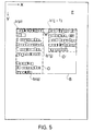
- the enveloping rectangle O is extended so that it also contains the new object box, whereupon the following object box is considered. If the distance w, on the other hand, is larger than the critical value W, then the enveloping rectangle associated with the previous object box, O, is closed and a new enveloping rectangle O' is formed around the new object box. This is shown in Fig. 5, where b'(j) is the last object box of enveloping rectangle O and object box b'(j+1) is a horizontal distance w, larger than W, away from the enveloping rectangle O. The closed enveloping rectangle O is then handled as a subblock of block B.
- the block B is divided into one or more adjoining subblocks.
- the processing sequence of the object boxes is optimal so that the division into subblocks takes place very rapidly.
- each subblock is in turn divided into smaller blocks by means of horizontal cuts. This proceeds in a similar manner to that described for vertical cuts, as follows:
- the smallest enveloping rectangle of the series is then determined for each following object box of the series, and the vertical distance h between the bottom of that object box and the enveloping rectangle associated with the previous object is also calculated. If the distance h is not larger than a predetermined critical value H, the enveloping rectangle is extended to include the new object box as well, whereupon the following object box is considered.
- the enveloping rectangle associated with the previous object box is closed and a new enveloping rectangle is formed around the new object box.
- the closed enveloping rectangle is then handled as a subblock of subblock O.
- the choice of the critical values W and H governs the result of the cuts and should be adapted to the level of the cut and to the size of the object boxes.
- W can be selected as being three times the average width of the object boxes, and for division of a line of text into words one and a half times the average distance between the boxes in the line (this can be calculated per line during the procedure).
- the cuts in the X and Y directions also govern the corner points of the layout structure of a document page, such as paragraphs, text columns, lines, etc.
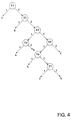
- the resulting layout structure can then be represented hierarchically in accordance with a tree structure.
- the method determines the position of the lefthand margin and in so doing uses the object boxes of the "character" type in the object box file.
- This file contains all the object boxes with the coordinates of their top left and bottom right corner. Where the following description refers to a box, it denotes a character object box.
- the method takes place in three phases:
- the object box file can be transformed so that the data therein relate to an aligned document.
- the first phase of the method starts with sorting the boxes by ascending X-coordinate and, for a constant X-coordinate, by ascending Y-coordinate, of their top left corner. This is shown in Fig. 6, where part of a skew text is shown rotated in the anticlockwise direction.
- Each character is provided with a box and a number of boxes is numbered I1 to I7, in the sequence in which they are sorted.
- the boxes are then read out and included in the same sequence in a list provided they have no overlap with a box already included in the list previously or with the white space between that box and the box thereabove. This is effected by comparing the segment on the Y-axis occupied by the new box with the segments on the Y-axis which are always limited by the Y-coordinate of the bottom righthand corner of a given box already included, and that of the bottom righthand corner of the already included box situated directly thereabove. Since the second and following characters of a line always overlap the first character, even in the event of a skew position, and can thus be eliminated, on completion the list will only contain the first box of each line.
- the first elements of the list are now thus formed by the boxes l1, l2, l3, l4, l5, l7, etc., in Fig. 6, since box I6 overlaps box l1 and is thus not included in the list.
- the boxes in the list are then resorted, now by ascending value of the Y-coordinate of their top lefthand corner. They are then read out from the list one by one and the direction vector from their top left corner to the top left corner of the next box from the list is calculated from the differences dx, dy of their X and Y coordinates. This is shown in Fig. 6, where the arrows always represent the direction vectors. This direction vector is now compared with that of the preceding box, and if its direction does not deviate therefrom by more than a value V, there is a chance that a margin has been found. There can incidentally be more than one margin on a page, e.g. in the case of an indented paragraph.
- the value V is recalculated for each box as a function of the difference in Y-coordinate between the two boxes between which the direction vector is calculated.
- a search is then made for the longest row of boxes whose direction vectors are equal within the tolerance V and this is then considered as (part of) the margin. From the two end points of the row a search is then made for other boxes situated outside the row and also situated on the margin. This would apply, for example, if there is an indented paragraph in the middle of a page. There are then two page parts, above and below the indented paragraph, situated on the same margin.
- the direction vector is first determined from the bottommost box of the row to the box beneath it and a check is made whether it is equal, within the tolerance V, to that applicable to the margin boxes.
- the resulting layout structure is also stored in memory 210.
- This structure contains the locations of all the character object boxes, and of all the higher elements formed by the text object boxes, such as blocks, lines and words, in addition to the locations and type of all the other object boxes.
- the keys BLOCK and LINE refer to elements of the "block” and “line” type respectively while OBJECT and PAGE refer to a single object box and the whole page respectively.
- the AREA key can be used to select a rectangular frame whose dimensions follow the movement of the light pen (known as "rubber banding" in personal computer technology).
- processing module 212 can be processed by processing module 212, from the series indicated under the heading OPERATION on the right of the control panel.
- the selected element is printed in a different colour.
- the UP and DOWN keys can be used to make a choice from a number of available colours. Information as to the possible choices then appears on the display.
- the processing module 212 then places a code in the memory 208 at the image dot data of the selected layout element, to instruct the printing unit 207 to print the relevant part of the image in the required colour.
- the SET CONTRAST operation can be used to control the reproduction characteristic (gradation) of the print for the selected element, the UP and DOWN keys making the reproduction harder and softer respectively. This is important, for example, if the original image is not sufficiently contrasty to give a clear image. In that case the processing module 212 selects a different conversion function from grey value image data to binary (white/black) image data for printing purposes during the halftoning operation.
- the selected document can be enlarged or reduced with the RESIZE operation (using the UP and DOWN keys), while INVERT is used to print it in negative form and ROTATE is used to rotate it in the image (the angle of rotation can be selected with the UP and DOWN keys).
- the CUT & PASTE heading contains keys for carrying out operations at the location of a selected document.
- a selected element is copied at the place indicated by the light pen.
- MOVE a selected element can be moved ("dragged") across the display while a selected element can be removed from the image with REMOVE.
- the heading INCLUDE contains the keys LOAD for loading image data from an external source, and CREATE PAGE for compiling a document page, for which it is possible to use the keys from the CUT & PASTE heading.
- an empty page image is shown on the display next to the page already selected and layout elements from the selected page can be transferred to the empty page in order thus to compile a new image, e.g. a clippings newssheet.
Landscapes
- Engineering & Computer Science (AREA)
- Multimedia (AREA)
- Signal Processing (AREA)
- Computer Vision & Pattern Recognition (AREA)
- Physics & Mathematics (AREA)
- Theoretical Computer Science (AREA)
- General Physics & Mathematics (AREA)
- Computer Graphics (AREA)
- Geometry (AREA)
- Artificial Intelligence (AREA)
- Processing Or Creating Images (AREA)
- Character Input (AREA)
- Editing Of Facsimile Originals (AREA)
- Facsimile Image Signal Circuits (AREA)
Description
- means for supplying digital image dot information representing said image,
- a memory for storing image dot information, and
- means for processing the supplied image dot information.
- segmentation means, connected to the memory, for automatically making a layout analysis of the image and correspondingly segmenting the digital image dot information into layout elements,
- operating means, connected to the segmentation means for receiving therefrom
results of the segmentation and being provided with:
- means for displaying said results to an operator,
- first selection means for selecting one or more layout elements found during the segmentation.
- second selection means for selecting a processing operation for changing the visual appearance of an image,
A touchsensitive display may also be used so that an operator can indicate the various elements with his finger.
- searching for the box situated furthest left in each line
- selecting from this set those boxes which really belong to the margin
- calculating the skew angle from the direction of the margin.
Claims (19)
- Apparatus for reproducing an image, comprisingsaid operating means (211) also being connected to the processing means (212) for controlling the same in order to process a layout element selected by said first selection means (203), in accordance with a processing operation selected by said second selection means (205).means (201) for supplying digital image dot information representing said image,a memory (208) for storing image dot information,means (212) for processing the supplied image dot information,means (207) for printing the processed image dot information on an image support,segmentation means (209), connected to the memory (208), for automatically making a layout-analysis of the image and correspondingly segmenting the digital image dot information into layout elements,operating means (211), connected to the segmentation means for receiving therefrom results of the segmentation and being provided with:means (202) for displaying said results to an operator,first selection means (203) for selecting one or more layout elements found during the segmentation, andsecond selection means (205) for selecting a processing operation for changing the visual appearance of an image,
- Apparatus according to claim 1, wherein the processing operation comprises changing the grey value scale.
- Apparatus according to claim 1, wherein the processing operation comprises changing the colour in the print on the image support.
- Apparatus according to claim 1, wherein the processing operation comprises the introduction of a raster.
- Apparatus according to claim 1, wherein the processing operation comprises changing the orientation.
- Apparatus according to claim 1, wherein the processing operation comprises changing the location.
- Apparatus according to claim 6, wherein the said processing operation for changing the location of a selected layout element comprises transferring said one or more layout elements to a separate image displayed on said displaying means (202).
- Apparatus according to claim 6 or 7, wherein the said processing operation for changing the location of a selected layout element comprises copying said layout element into a separate image displayed on said displaying means (202).
- Apparatus for processing digital image dot information representing an image, comprisingsaid operating means (211) also being connected to the processing means for controlling the same in processing digital image dot information representing a layout element selected by said first selection means (203), in accordance with a transfer operation selected by said third selection means (205).means (201) for supplying digital image dot information representing said image,a memory (208) for storing image dot information,means (212) for processing the supplied image dot information,segmentation means (209), connected to the memory (208), for automatically segmenting the digital image dot information into layout elements,operating means (211), connected to the segmentation means for receiving therefrom results of the segmentation, and being provided with:means (202) for displaying said results to an operator,first selection means (203) for selecting one or more layout elements found during the segmentation, andthird selection means (205) for selecting a transfer operation for transferring a layout element to another location,
- Apparatus in accordance with claim 9, wherein said processing means (212) includes means for creating a receiving image, and means for copying or transferring a selected layout element thereto.
- Apparatus in accordance with claim 10, wherein said operating means (211) includes a so-called "cut & paste" function, for an operator to command a copy or transfer operation of a selected layout element to said receiving image.
- Apparatus in accordance with claim 10, wherein said means (202) for displaying said image displays the same together with said receiving image.
- Apparatus in accordance with claim 10 or 12, wherein the processing means (212) is adapted to compile a receiving image from layout elements transferred or copied thereto.
- Apparatus in accordance with claim 9, also including printing means (207) connected to said processing means (212) for printing digital image dot information representing a selected layout element, on an image support.
- Method of processing a document image, comprising the following steps:having digital image dot information representing said image,automatically segmenting said digital image dot information into layout elements,presenting said image to an operator for selection of one or more of the layout elements found in the segmenting step,presenting for selection, to an operator, at least one transfer operation for transferring a layout element to another location,processing digital image dot information representing a selected layout element, in accordance with a selected transfer operation.
- Method according to claim 15, also comprising the step of creating a receiving image, wherein said step of processing comprises copying or transferring a selected layout element to said receiving image.
- Method according to claim 16, further including displaying said receiving image to an operator.
- Method according to claim 16, further including compiling a receiving image from layout elements transferred or copied thereto.
- Method according to any of claim 15, wherein said digital image dot information representing layout elements selected by the operator is outputted to a printer.
Applications Claiming Priority (2)
| Application Number | Priority Date | Filing Date | Title |
|---|---|---|---|
| NL9301004 | 1993-06-11 | ||
| NL9301004A NL9301004A (en) | 1993-06-11 | 1993-06-11 | Apparatus for processing and reproducing digital image information. |
Publications (2)
| Publication Number | Publication Date |
|---|---|
| EP0629078A1 EP0629078A1 (en) | 1994-12-14 |
| EP0629078B1 true EP0629078B1 (en) | 1999-10-13 |
Family
ID=19862518
Family Applications (1)
| Application Number | Title | Priority Date | Filing Date |
|---|---|---|---|
| EP94201606A Expired - Lifetime EP0629078B1 (en) | 1993-06-11 | 1994-06-06 | Apparatus for processing and reproducing image information |
Country Status (5)
| Country | Link |
|---|---|
| US (1) | US5856877A (en) |
| EP (1) | EP0629078B1 (en) |
| JP (1) | JP2854804B2 (en) |
| DE (2) | DE69421117T2 (en) |
| NL (1) | NL9301004A (en) |
Cited By (1)
| Publication number | Priority date | Publication date | Assignee | Title |
|---|---|---|---|---|
| US6999616B2 (en) | 2000-08-16 | 2006-02-14 | Océ-Technologies B.V. | Interpretation of colored documents |
Families Citing this family (30)
| Publication number | Priority date | Publication date | Assignee | Title |
|---|---|---|---|---|
| JPH07131641A (en) * | 1993-11-08 | 1995-05-19 | Canon Inc | Image processing device |
| NL1000701C2 (en) | 1995-06-30 | 1996-12-31 | Oce Nederland Bv | Device and method for extracting articles from a document. |
| US6389162B2 (en) | 1996-02-15 | 2002-05-14 | Canon Kabushiki Kaisha | Image processing apparatus and method and medium |
| JPH10145601A (en) * | 1996-11-08 | 1998-05-29 | Ricoh Co Ltd | Image processing device |
| US5920406A (en) * | 1997-06-13 | 1999-07-06 | Hewlett-Packard Co. | Margin seeking for multiple copy jobs |
| FR2766286B1 (en) * | 1997-07-17 | 2000-09-08 | Jean Pierre Alfred Arnaud | PROCESS FOR CREATING DOCUMENTS FOR PRINTING |
| EP0991265A3 (en) * | 1998-10-01 | 2003-08-27 | Hewlett-Packard Company, A Delaware Corporation | User interface high-lighter function to provide directed input for image processing |
| US6674901B1 (en) * | 1999-04-21 | 2004-01-06 | Hewlett-Packard Development Company, L.P. | Document analysis system and method |
| DE10000935C2 (en) * | 1999-05-13 | 2003-07-31 | Hewlett Packard Co | Device and method for controlling a document area analysis |
| US6880122B1 (en) | 1999-05-13 | 2005-04-12 | Hewlett-Packard Development Company, L.P. | Segmenting a document into regions associated with a data type, and assigning pipelines to process such regions |
| JP3895892B2 (en) * | 1999-09-22 | 2007-03-22 | 株式会社東芝 | Multimedia information collection management device and storage medium storing program |
| US7184167B1 (en) | 1999-09-30 | 2007-02-27 | Brother Kogyo Kabushiki Kaisha | Data processing for arranging text and image data on a substrate |
| US7411593B2 (en) * | 2001-03-28 | 2008-08-12 | International Business Machines Corporation | Image rotation with substantially no aliasing error |
| GB2380646A (en) | 2001-10-05 | 2003-04-09 | Ibm | Image segmentation |
| US20030095722A1 (en) * | 2001-11-19 | 2003-05-22 | Regimbal Laurent A. | Method and apparatus to detect and compensate for skew in a printing device |
| JP2004040776A (en) * | 2002-05-27 | 2004-02-05 | Oce Technologies Bv | Processing of digital mixed color document |
| US6810136B2 (en) * | 2002-10-18 | 2004-10-26 | Olive Software Inc. | System and method for automatic preparation of data repositories from microfilm-type materials |
| AU2003902362A0 (en) * | 2003-05-14 | 2003-05-29 | Outback Software Pty Limited | Arranging components on a sheet |
| EP1603072A1 (en) | 2004-06-02 | 2005-12-07 | CCS Content Conversion Specialists GmbH | Process and apparatus for analysing the structure of a document |
| US20070002375A1 (en) * | 2005-06-30 | 2007-01-04 | Lexmark International, Inc. | Segmenting and aligning a plurality of cards in a multi-card image |
| TW201001303A (en) * | 2008-06-27 | 2010-01-01 | Univ Nat Taiwan Science Tech | System and method for recognizing document immediately |
| US8351691B2 (en) * | 2008-12-18 | 2013-01-08 | Canon Kabushiki Kaisha | Object extraction in colour compound documents |
| US8443278B2 (en) * | 2009-01-02 | 2013-05-14 | Apple Inc. | Identification of tables in an unstructured document |
| KR101035739B1 (en) * | 2009-02-13 | 2011-05-20 | 전남대학교산학협력단 | How to correct distortion of character recognition |
| US8549399B2 (en) | 2011-01-18 | 2013-10-01 | Apple Inc. | Identifying a selection of content in a structured document |
| US8380753B2 (en) | 2011-01-18 | 2013-02-19 | Apple Inc. | Reconstruction of lists in a document |
| CN102789658B (en) * | 2012-03-02 | 2015-02-18 | 成都三泰电子实业股份有限公司 | Ultraviolet anti-counterfeiting check authenticity verification method |
| CN105793918B (en) * | 2013-09-27 | 2019-01-22 | 皇家飞利浦有限公司 | Simultaneous display of video data from multiple video sources |
| CN110126484A (en) * | 2019-05-30 | 2019-08-16 | 深圳龙图腾创新设计有限公司 | A kind of printing device |
| US11199652B2 (en) * | 2020-02-07 | 2021-12-14 | Sony Interactive Entertainment Inc. | Active privacy screen |
Family Cites Families (10)
| Publication number | Priority date | Publication date | Assignee | Title |
|---|---|---|---|---|
| US3848856A (en) * | 1973-10-01 | 1974-11-19 | Hazeltine Corp | Local correction apparatus for a color previewer |
| DE2430762A1 (en) * | 1974-06-26 | 1976-01-15 | Gruner & Jahr | PROCESS FOR INFORMATION PROCESSING FOR THE PRODUCTION OF A PRINTING FORM AND DEVICE FOR CARRYING OUT THE PROCESS |
| JPS57197671A (en) * | 1981-05-29 | 1982-12-03 | Nec Corp | Editing method for picture and character train |
| JPS60121878A (en) * | 1983-12-06 | 1985-06-29 | Dainippon Screen Mfg Co Ltd | Duplicating system of picture scanning |
| JPS62135257U (en) * | 1986-02-19 | 1987-08-26 | ||
| US4985930A (en) * | 1987-09-24 | 1991-01-15 | Hitachi, Ltd. | Image data filing system and image data correcting method |
| JP2662429B2 (en) * | 1988-11-14 | 1997-10-15 | キヤノン株式会社 | Image editing device |
| JPH0388087A (en) * | 1989-08-31 | 1991-04-12 | Toshiba Corp | Document reader |
| JP2598723B2 (en) * | 1990-06-28 | 1997-04-09 | 大日本スクリーン製造株式会社 | Halftone image creation device |
| JPH04248687A (en) * | 1991-01-23 | 1992-09-04 | Internatl Business Mach Corp <Ibm> | Layout analyzing method and system of document picture |
-
1993
- 1993-06-11 NL NL9301004A patent/NL9301004A/en not_active Application Discontinuation
-
1994
- 1994-06-02 JP JP6121160A patent/JP2854804B2/en not_active Expired - Fee Related
- 1994-06-06 EP EP94201606A patent/EP0629078B1/en not_active Expired - Lifetime
- 1994-06-06 DE DE69421117T patent/DE69421117T2/en not_active Expired - Lifetime
- 1994-06-06 DE DE0629078T patent/DE629078T1/en active Pending
-
1996
- 1996-07-03 US US08/999,834 patent/US5856877A/en not_active Expired - Lifetime
Cited By (1)
| Publication number | Priority date | Publication date | Assignee | Title |
|---|---|---|---|---|
| US6999616B2 (en) | 2000-08-16 | 2006-02-14 | Océ-Technologies B.V. | Interpretation of colored documents |
Also Published As
| Publication number | Publication date |
|---|---|
| US5856877A (en) | 1999-01-05 |
| JP2854804B2 (en) | 1999-02-10 |
| DE69421117D1 (en) | 1999-11-18 |
| EP0629078A1 (en) | 1994-12-14 |
| DE69421117T2 (en) | 2000-04-06 |
| JPH0750751A (en) | 1995-02-21 |
| NL9301004A (en) | 1995-01-02 |
| DE629078T1 (en) | 1996-05-02 |
Similar Documents
| Publication | Publication Date | Title |
|---|---|---|
| EP0629078B1 (en) | Apparatus for processing and reproducing image information | |
| US5528732A (en) | Reprographic device for making copies with multi-spaced lines | |
| JP2536966B2 (en) | Text editing system | |
| US4985930A (en) | Image data filing system and image data correcting method | |
| US4748678A (en) | Method of storing and retrieving image data | |
| EP0738987B1 (en) | Processing machine readable forms | |
| US5761344A (en) | Image pre-processor for character recognition system | |
| US5179649A (en) | Method for generating title information entry format and method for filing images in image filing device | |
| US5201011A (en) | Method and apparatus for image hand markup detection using morphological techniques | |
| US5101448A (en) | Method and apparatus for processing a document by utilizing an image | |
| US5854854A (en) | Skew detection and correction of a document image representation | |
| EP0439951B1 (en) | Data processing | |
| US5642473A (en) | Paper saving reprographic device | |
| JP3048330B2 (en) | Apparatus and method for extracting articles from documents | |
| US5392130A (en) | Analyzing an image showing a row/column representation | |
| JPS63268081A (en) | Method and apparatus for recognizing character of document | |
| US5509092A (en) | Method and apparatus for generating information on recognized characters | |
| US5257074A (en) | Image forming apparatus | |
| US5745664A (en) | Image synthesizing method and image recording apparatus which electronically synthesizes an image with a page of information | |
| JP4098845B2 (en) | How to compare symbols extracted from binary images of text | |
| US6163623A (en) | Method and apparatus for recognizing images of documents and storing different types of information in different files | |
| US5974177A (en) | Apparatus and method of network distribution of record data using transmittal symbols hand entered on a transmittal sheet | |
| US5592574A (en) | Method and apparatus for expansion of white space in document images on a digital scanning device | |
| CN100349454C (en) | Image forming apparatus, image forming method, program therefor, and storage medium | |
| US7149352B2 (en) | Image processing device, program product and system |
Legal Events
| Date | Code | Title | Description |
|---|---|---|---|
| PUAI | Public reference made under article 153(3) epc to a published international application that has entered the european phase |
Free format text: ORIGINAL CODE: 0009012 |
|
| AK | Designated contracting states |
Kind code of ref document: A1 Designated state(s): DE FR GB IT NL |
|
| 17P | Request for examination filed |
Effective date: 19950602 |
|
| DET | De: translation of patent claims | ||
| 17Q | First examination report despatched |
Effective date: 19970520 |
|
| RAP1 | Party data changed (applicant data changed or rights of an application transferred) |
Owner name: OCE-TECHNOLOGIES B.V. |
|
| GRAG | Despatch of communication of intention to grant |
Free format text: ORIGINAL CODE: EPIDOS AGRA |
|
| GRAG | Despatch of communication of intention to grant |
Free format text: ORIGINAL CODE: EPIDOS AGRA |
|
| GRAH | Despatch of communication of intention to grant a patent |
Free format text: ORIGINAL CODE: EPIDOS IGRA |
|
| GRAH | Despatch of communication of intention to grant a patent |
Free format text: ORIGINAL CODE: EPIDOS IGRA |
|
| GRAA | (expected) grant |
Free format text: ORIGINAL CODE: 0009210 |
|
| RIC1 | Information provided on ipc code assigned before grant |
Free format text: 6H 04N 1/40 A, 6G 06K 9/20 B, 6G 06F 15/70 B |
|
| AK | Designated contracting states |
Kind code of ref document: B1 Designated state(s): DE FR GB IT NL |
|
| RIC1 | Information provided on ipc code assigned before grant |
Free format text: 6H 04N 1/40 A, 6G 06K 9/20 B |
|
| REF | Corresponds to: |
Ref document number: 69421117 Country of ref document: DE Date of ref document: 19991118 |
|
| ITF | It: translation for a ep patent filed | ||
| ET | Fr: translation filed | ||
| PLBE | No opposition filed within time limit |
Free format text: ORIGINAL CODE: 0009261 |
|
| STAA | Information on the status of an ep patent application or granted ep patent |
Free format text: STATUS: NO OPPOSITION FILED WITHIN TIME LIMIT |
|
| 26N | No opposition filed | ||
| REG | Reference to a national code |
Ref country code: GB Ref legal event code: IF02 |
|
| PGFP | Annual fee paid to national office [announced via postgrant information from national office to epo] |
Ref country code: IT Payment date: 20080530 Year of fee payment: 15 |
|
| PG25 | Lapsed in a contracting state [announced via postgrant information from national office to epo] |
Ref country code: IT Free format text: LAPSE BECAUSE OF NON-PAYMENT OF DUE FEES Effective date: 20090606 |
|
| PGFP | Annual fee paid to national office [announced via postgrant information from national office to epo] |
Ref country code: DE Payment date: 20130620 Year of fee payment: 20 Ref country code: GB Payment date: 20130619 Year of fee payment: 20 |
|
| PGFP | Annual fee paid to national office [announced via postgrant information from national office to epo] |
Ref country code: NL Payment date: 20130617 Year of fee payment: 20 Ref country code: FR Payment date: 20130703 Year of fee payment: 20 |
|
| REG | Reference to a national code |
Ref country code: DE Ref legal event code: R071 Ref document number: 69421117 Country of ref document: DE |
|
| REG | Reference to a national code |
Ref country code: NL Ref legal event code: V4 Effective date: 20140606 |
|
| REG | Reference to a national code |
Ref country code: GB Ref legal event code: PE20 Expiry date: 20140605 |
|
| PG25 | Lapsed in a contracting state [announced via postgrant information from national office to epo] |
Ref country code: GB Free format text: LAPSE BECAUSE OF EXPIRATION OF PROTECTION Effective date: 20140605 |
|
| PG25 | Lapsed in a contracting state [announced via postgrant information from national office to epo] |
Ref country code: DE Free format text: LAPSE BECAUSE OF EXPIRATION OF PROTECTION Effective date: 20140607 |