EP0629069B1 - Multi-carrier transmission method - Google Patents
Multi-carrier transmission method Download PDFInfo
- Publication number
- EP0629069B1 EP0629069B1 EP94106869A EP94106869A EP0629069B1 EP 0629069 B1 EP0629069 B1 EP 0629069B1 EP 94106869 A EP94106869 A EP 94106869A EP 94106869 A EP94106869 A EP 94106869A EP 0629069 B1 EP0629069 B1 EP 0629069B1
- Authority
- EP
- European Patent Office
- Prior art keywords
- amplitude
- modulation
- phase states
- individual
- carrier
- Prior art date
- Legal status (The legal status is an assumption and is not a legal conclusion. Google has not performed a legal analysis and makes no representation as to the accuracy of the status listed.)
- Expired - Lifetime
Links
Images


Classifications
-
- H—ELECTRICITY
- H04—ELECTRIC COMMUNICATION TECHNIQUE
- H04L—TRANSMISSION OF DIGITAL INFORMATION, e.g. TELEGRAPHIC COMMUNICATION
- H04L27/00—Modulated-carrier systems
- H04L27/32—Carrier systems characterised by combinations of two or more of the types covered by groups H04L27/02, H04L27/10, H04L27/18 or H04L27/26
- H04L27/34—Amplitude- and phase-modulated carrier systems, e.g. quadrature-amplitude modulated carrier systems
- H04L27/3405—Modifications of the signal space to increase the efficiency of transmission, e.g. reduction of the bit error rate, bandwidth, or average power
- H04L27/3411—Modifications of the signal space to increase the efficiency of transmission, e.g. reduction of the bit error rate, bandwidth, or average power reducing the peak to average power ratio or the mean power of the constellation; Arrangements for increasing the shape gain of a signal set
-
- H—ELECTRICITY
- H04—ELECTRIC COMMUNICATION TECHNIQUE
- H04L—TRANSMISSION OF DIGITAL INFORMATION, e.g. TELEGRAPHIC COMMUNICATION
- H04L27/00—Modulated-carrier systems
- H04L27/32—Carrier systems characterised by combinations of two or more of the types covered by groups H04L27/02, H04L27/10, H04L27/18 or H04L27/26
- H04L27/34—Amplitude- and phase-modulated carrier systems, e.g. quadrature-amplitude modulated carrier systems
- H04L27/3405—Modifications of the signal space to increase the efficiency of transmission, e.g. reduction of the bit error rate, bandwidth, or average power
Landscapes
- Engineering & Computer Science (AREA)
- Computer Networks & Wireless Communication (AREA)
- Signal Processing (AREA)
- Digital Transmission Methods That Use Modulated Carrier Waves (AREA)
- Radio Transmission System (AREA)
- Instructional Devices (AREA)
Abstract
Description
Die Erfindung betrifft und geht aus von einem Multiträger-Übertragungsverfahren laut Oberbegriff des Patentanspruches.The invention relates to and is based on a multi-carrier transmission method according to the preamble of the claim.
Multiträger-Übertragungsverfahren, bei denen eine Vielzahl von einzelnen nebeneinanderliegenden Trägern benutzt wird, sind bekannt. Ein solches Verfahren wird beispielsweise beim DAB-Hörfunk-System (Digital-Audio-Broadcasting, beschrieben in ITU, COM'89, Genf, Oktober 1989 bzw. "Künftige Systeme der digitalen Hörfunkübertragung", Bayerischer Rundfunk, November 1990) mit 1536 einzelnen Trägern pro übertragenem Signalpaket benutzt. Dabei ist es auch schon bekannt, für die Modulation der einzelnen Träger ein höherwertiges Modulationsverfahren mit mehreren Amplituden- und Phasenzuständen zu benutzen, beispielsweise eine 8PSK (Phase-Shift-Keying mit 8 Phasenzuständen)- oder eine 16QAM (Quadratur-Amplituden-Modulation mit 16 Amplitudenzuständen)-Modulation (beschrieben in Mäusl, "Digitale Modulationsverfahren", Hüthig-Verlag, S. 230-244 bzw. Meinke-Gundlach, Taschenbuch der Hochfrequenztechnik, 5. Auflage, S. O 19 bis O 24).Multi-carrier transmission methods in which a large number of individual carriers lying next to one another are used are known. Such a process is for example in the DAB radio system (D igital- A udio- B road casting, described in ITU, COM'89, Geneva, October 1989 and "Future systems, digital radio broadcasting", Bayerischer Rundfunk, Nov. 1990) with 1536 individual carriers used per transmitted signal packet. It is also already known to use a high-order modulation process with several amplitude and phase states of the modulation of the individual carriers, for example, an 8PSK (P Hare S hift- K eying with 8 phase states) - or a 16QAM (Q uadratur- A mplituden- M odulation with 16 amplitude states) modulation (described in Mäusl, "Digital modulation", Huthig-Verlag, pp 230-244 and Meinke-Gundlach, Taschenbuch high-frequency technology, 5th edition, p O O 19 to 24 ).
Solche Multiträger-Übertragungsverfahren besitzen den Vorteil, daß sehr frequenzökonomische Gleichwellennetze realisierbar sind und daß sie auch für den mobilen Empfang geeignet sind, bei Einsatz von höherwertigen Modulationsverfahren sind sie außerdem zur Übertragung von hohen Datenraten bis zu ca. 35 Mbit/s und damit für künftige DTVB-T (Digitale-Television-Broadcasting-Terrestrial)-Systeme geeignet.Such multicarrier transmission methods have the advantage that very frequency-efficient single-frequency networks can be implemented and that they are also suitable for mobile reception.If higher-quality modulation methods are used, they are also for the transmission of high data rates up to approx. 35 Mbit / s and thus for future ones DTVB-T (D T igitale- elevision- B road casting T e rrestrial) systems suitable.
Nachteilig ist bei solchen Multiträger-Übertragungsverfahren, daß hierbei Signale mit hohem Crestfaktor (Verhältnis von Spitzenwert zu Mittelwert) entstehen, also Signale, die mit weißem Rauschen vergleichbar sind. Daher sind zur Übertragung überdimensionierte Senderverstärker mit entsprechend geringem Wirkungsgrad erforderlich, die relativ hohe Investitions-, Energie- und Servicekosten bedingen. Die endliche Linearität und Aussteuerbarkeit der Verstärker führt außerdem zu Intermodulationsprodukten und damit zu Störungen benachbarter Übertragungsdienste, außerdem zu Inbandstörungen, durch welche die Fehlerrate vergrößert und die Übertragungsqualität verschlechtert wird.The disadvantage of such multi-carrier transmission methods is that signals with a high crest factor (ratio from peak value to mean value) Signals comparable to white noise. Therefore are oversized transmitter amplifiers for transmission required with correspondingly low efficiency, the relatively high investment, energy and service costs condition. The finite linearity and controllability the amplifier also leads to intermodulation products and thus to disturbances of neighboring transmission services, also to inband disturbances, by which the error rate enlarged and the transmission quality deteriorated becomes.
Es ist auch schon bekannt, zur Übertragung von digitalen Daten über einen einzigen Träger (Mono-Sinusträger) die Lage der einzelnen Amplituden- und Phasenzustände im Vektordiagramm sowohl bezüglich Phase als auch bezüglich Amplitude nach ausgewählten Optimierungskriterien der Modulation beliebig frei zu wählen, beispielsweise so, daß die mittlere Senderleistung bei gleichen Entscheidungskreisen auf ein Minimum reduziert wird bzw. die Größe der Entscheidungskreise bei gleichem umfassenden Kreis (Aussteuerung) ein Maximum wird (z.B. nach IEEE International Conference on Communications - ICC'90, Atlanta, Ramseier S. "Bandwidth-Efficient Trellis Coded Modulation Schemes" S. 1517-1521). Diese Modulationsoptimierung bei Mono-Trägern wurde bisher nicht bei Multiträger-Verfahren angewendet, hierfür wurden allenfalls die eingangs erwähnten bekannten höherwertigen Modulationsverfahren wie 16QAM oder 64QAM für praktisch anwendbar angesehen, bei denen die Modulationspunkte nach Art eines quadratischen Gittermusters angeordnet werden, das empfängerseitig auf einfache Weise durch eine Größer/Kleiner-Entscheidung demoduliert werden kann.It is also known to transmit digital Data on a single carrier (mono sine carrier) Location of the individual amplitude and phase states in Vector diagram regarding both phase and Amplitude according to selected optimization criteria of Free choice of modulation, for example, that the mean transmitter power with the same decision circles is reduced to a minimum or Size of decision-making circles with the same comprehensive Circle (modulation) becomes a maximum (e.g. according to IEEE International Conference on Communications - ICC'90, Atlanta, Ramseier S. "Bandwidth-Efficient Trellis Coded Modulation Schemes "pp. 1517-1521). This modulation optimization Mono carriers have not been used for Multi-carrier process applied, at best for this the known higher quality mentioned at the beginning Modulation methods like 16QAM or 64QAM for practical applicable where the modulation points arranged in the manner of a square grid pattern be done by the recipient in a simple manner a larger / smaller decision can be demodulated.
Es ist Aufgabe der Erfindung, ein Multiträger-Übertragungsverfahren der eingangs erwähnten Art bezüglich der aufgezeigten Nachteile zu verbessern.The object of the invention is a multi-carrier transmission method of the type mentioned at the beginning with regard to to improve identified disadvantages.
Diese Aufgabe wird gelöst durch die Kombination laut Patentanspruch.This task is solved by the combination loudly Claim.
Bei der erfindungsgemäßen Kombination wird für jeden einzelnen Träger eines Multiträger-Übertragungsverfahrens die Lage der Amplituden- und Phasenzustände so gewählt, daß es bezüglich ausgewählter Modulationskriterien optimal wird. So kann beispielsweise die Modulation jedes einzelnen Trägers bezüglich Senderleistung (Power Optimized Modulation, POM) oder bezüglich der Größe und Zuordnung der Entscheidungskreise der einzelnen Phasenzustände (Circle Optimized Modulation, COM) optimiert werden. Damit kann den eingangs geschilderten Nachteilen der bekannten Multiträger-Übertragungsverfahren entgegengewirkt werden, überdimensionierte Senderverstärker werden vermieden, da die erzeugten Signale bei der erfindungsgemäßen Kombination nicht nur eine geringere effektive d.h. thermische Leistung aufweisen, sondern überraschenderweise auch einen geringeren Crestfaktor. Auch die Intermodulationsprodukte und Inbandstörungen werden verringert, ohne daß die Komplexität des Senders bzw. der Empfänger vergrößert wird. Die Realisierung der POM-bzw. COM-Multiträger erfolgt senderseitig durch eine entsprechende Software eines Prozessors und damit ohne Erhöhung der Herstellungskosten des Senders gegenüber einem bekannten Multiträger-Verfahren mit höherwertiger Modulation (z.B. mit QAM), im Empfänger ist eine Demodulation auf einfache Weise nur durch entsprechende Optimierung des verwendeten Decodieralgorithmus möglich, also ebenfalls ohne nennenswerte Erhöhung der Komplexität des Empfängers.In the combination according to the invention, the position of the amplitude and phase states is selected for each individual carrier of a multi-carrier transmission method in such a way that it is optimal with regard to selected modulation criteria. Thus, the modulation can, for example, of each individual carrier with respect to transmitter power (P ower O ptimized M odulation, POM), or on the size and allocation of the decision circuits of the individual phase states (C ircle O ptimized M odulation, COM) to be optimized. The disadvantages of the known multi-carrier transmission methods described at the outset can thus be counteracted, oversized transmitter amplifiers are avoided since the signals generated in the combination according to the invention not only have a lower effective, ie thermal power, but surprisingly also a lower crest factor. The intermodulation products and in-band interference are also reduced without increasing the complexity of the transmitter or the receiver. The realization of the POM or. COM multicarrier is carried out on the transmitter side by appropriate software of a processor and thus without increasing the manufacturing costs of the transmitter compared to a known multicarrier method with higher quality modulation (e.g. with QAM), in the receiver demodulation is only possible in a simple manner by appropriate optimization of the decoding algorithm used , also without any significant increase in the complexity of the receiver.
Die Erfindung wird im folgenden anhand schematischer Zeichnungen an Ausführungsbeispielen näher erläutert.The invention will now be described more schematically Drawings explained in more detail using exemplary embodiments.
Fig. 1 zeigt eine übliche 8PSK-Modulation, bei der die einzelnen jeweils mit gleicher Amplitude A1 bis A8 umgetasteten unterschiedlichen Phasenzustände 1-8 auf einen Kreis symmetrisch zum Mittelpunkt des Vektordiagramms angeordnet sind. Die jedem einzelnen Phasenzustand zugeordneten Entscheidungskreise, innerhalb welcher eine eindeutige Zustandserkennung gewährleistet ist, sind unmittelbar aneinander anschließend und sich berührend ausgebildet.1 shows a customary 8PSK modulation, in which the individual different phase states 1 - 8, each keyed with the same amplitude A1 to A8, are arranged on a circle symmetrically to the center of the vector diagram. The decision circles assigned to each individual phase state, within which a clear state detection is guaranteed, are directly connected and touching.
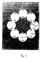
Fig. 2 zeigt eine bezüglich Senderleistung optimierte Anordnung der Amplituden- und Phasenzustände a1, 1 bis a8, 8 einer 8PSK Modulation gemäß Fig. 1. Nach Fig. 2 sind die einzelnen Entscheidungskreise r der einzelnen Amplituden- und Phasenzustände nicht mehr kranzförmig gemäß Fig. 1 angeordnet, sondern im Vektordiagramm V so ineinander verschachtelt, daß nur noch vier Amplituden- und Phasenzustände auf einem äußeren Kreis R1 liegen, während vier der Amplituden- und Phasenzustände so nach innen in Richtung auf den Mittelpunkt des Vektordiagramms verschoben sind, daß sie auf einem kleineren Kreis R2 liegen. Fig. 2 zeigt außerdem, daß die Größe der Entscheidungskreise gegenüber Fig. 1 gleich sind und diese Entscheidungskreise sich wieder unmittelbar berühren. Eine solche als 8POM (Power Optimized Modulation) bezeichnete Modulationsart nach Fig. 2 besitzt den Vorteil, daß die mittlere Sendeleistung um ca. 2,0 dB (37 %) reduziert ist unter Beibehaltung der Entscheidungskreise (Übertragungssicherheit).FIG. 2 shows an arrangement of the amplitude and phase states a 1 , 1 to a 8 , einer 8 of an 8PSK modulation according to FIG. 1 which is optimized with respect to transmitter power. According to FIG. 2, the individual decision circles r of the individual amplitude and phase states are no longer 1, but nested in the vector diagram V such that only four amplitude and phase states lie on an outer circle R1, while four of the amplitude and phase states are shifted inward towards the center of the vector diagram, that they are on a smaller circle R2. Fig. 2 also shows that the size of the decision circles compared to Fig. 1 are the same and these decision circles touch each other again. Such a type of modulation, referred to as 8POM (Power Optimized Modulation) according to FIG. 2, has the advantage that the average transmission power is reduced by approximately 2.0 dB (37%) while maintaining the decision-making circles (transmission security).
Die Leistungsreduktion kann auch als Modulationsgewinn betrachtet werden und sich in anderen Vorteilen wie größere Versorgungsfläche, geringere Bitfehlerrate oder geringere Dimension der Empfangsantenne ausdrücken.The power reduction can also be used as a modulation gain be considered and other benefits such as larger coverage area, lower bit error rate or Express the smaller dimension of the receiving antenna.
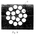
Fig. 3 zeigt ein übliches 16QAM-Modulationsverfahren mit 16 in Reihen und Zeilen nebeneinander angeordneten Amplituden- und Phasenzuständen a1, 1 bis a16,ϕ16, denen jeweils gleich große Entscheidungskreise r1 zugeordnet sind. Gemäß Fig. 4 können diese Amplituden- und Phasenzustände mit zugehörigen gleich großen Entscheidungskreisen so innerhalb des umfassenden Kreises U mit Radius R3 verteilt werden, daß sich die aus Fig. 3 übernommenen Entscheidungskreise nicht mehr berühren. Damit ergeben sich die tatsächlichen, sich berührenden Entscheidungskreise größer, also ist das Modulationsverfahren bezüglich eindeutiger Zustandserkennung optimiert (16 COM = Circle Optimized Modulation). Die Fläche jedes einzelnen Entscheidungskreises für die jeweiligen Amplituden- und Phasenzustände kann auf diese Weise um ca. 35 % vergrößert werden und zwar unter Beibehaltung der gemäß Fig. 3 vorgegebenen Spitzenaussteuerung (Spitzenleistung). Fig. 5 zeigt eine andere Möglichkeit zur Optimierung des ursprünglichen 16 QAM-Verfahrens nach Fig. 3 und zwar wird hier unter Beibehaltung der Größe der Entscheidungskreise wieder bezüglich Leistung optimiert, durch die in Fig. 5 dargestellte Anordnung der Entscheidungskreise kann die mittlere Leistung um ca. 0,47 dB (10 %) verringert werden. 3 shows a conventional 16QAM modulation method with 16 amplitude and phase states a 1 , 1 to a 16 , ϕ 16 arranged side by side in rows and rows, to which decision circles r 1 of the same size are assigned. According to FIG. 4, these amplitude and phase states with associated decision circles of equal size can be distributed within the comprehensive circle U with radius R 3 such that the decision circles adopted from FIG. 3 no longer touch. This means that the actual, touching decision-making circles are larger, so the modulation process is optimized with regard to clear status detection (16 COM = Circle Optimized Modulation). The area of each individual decision circle for the respective amplitude and phase states can be increased in this way by approx. 35% while maintaining the peak modulation (peak power) specified according to FIG. 3. FIG. 5 shows another possibility for optimizing the original 16 QAM method according to FIG. 3, namely that the performance is optimized again while maintaining the size of the decision circles. The arrangement of the decision circles shown in FIG 0.47 dB (10%) can be reduced.
Diese an sich bekannte Modulationsoptimierung gemäß Fig. 1 bis 4 wird gemäß der Erfindung für jeden einzelnen Träger eines bekannten Multiträger-Übertragungsverfahrens benutzt, bei dem eine Vielzahl von einzelnen nebeneinanderliegenden Trägern vorgesehen ist. Jeder Träger wird also nach diesem an sich für Mono-Träger-Übertragungsverfahren bekannten Modulationsverfahren moduliert. Hierfür eignen sich vor allem die mittlerweile angebotenen Digitaltechniken mit Mikrokontroller und digitalen Signalprozessoren, wie sie beispielsweise beschrieben sind in SHARP " An Ultra-High Speed DSP Chip Set For Real-Time Applications", M.E. Fleming, Sharp Electronics GmbH, Hamburg. Fig. 5 zeigt den Prinzipaufbau eines solchen digital arbeitenden Modulators unter Benutzung einer IFFT (Inverse Fast Fourier Transformation).This known modulation optimization according to FIG. 1 to 4 is according to the invention for each individual carrier a known multi-carrier transmission method used where a multitude of individual ones lying side by side Carriers is provided. So every carrier becomes after this known per se for mono-carrier transmission methods Modulation process modulated. Above all, they are suitable for this the digital technologies that are now available with microcontrollers and digital signal processors, such as those are described in SHARP "An Ultra-High Speed DSP Chip Set For Real-Time Applications ", M.E. Fleming, Sharp Electronics GmbH, Hamburg. Fig. 5 shows the Principle structure of such a digitally working modulator using a IFFT (Inverse Fast Fourier Transformation).
Der auf die Träger des Multiträgerpaketes aufzumodulierende serielle Datenstrom
wird in einem Prozessor 10 aufbereitet und zwar so, daß entsprechend der Wetigkeit
der Modulation (z. B. 8POM nach Fig. 2) die hier abgespeicherten
komplexen Amplituden- und Phasenzustände (z.B. a1, ϕ1 bis a8, ϕ8) nach Realteil
und Imaginärteil adressiert und dann einem FET-Prozessor 11 für die IFFT zugeführt
werden. In diesem Prozessor 11 wird dann entlang der Schrittlänge, d. h. die
Zeit, in der die Modulationspunkte aller Träger des Multiträgerpaketes konstant
sind, die IFFT durchgeführt und liefert in der Zeitebene die Abtastwerte in äquidistanten
Schritten nach den Gesetzen der Fourier-Transformation. Die so erzeugten
digitalen I- und Q-Werte werden anschließend über Digital/Analog-Wandler in
entsprechende analoge Signale IA bzw. QA umgewandelt und dann einem üblichen
IQ-Modulator, aufgebaut aus zwei Zweiseitenbandmodulatoren 12 und 13
mit jeweils gegeneinander um 90° phasenversetzten Trägern in das Modulationssignal
umgesetzt, das dann unmittelbar dem Sender zugeführt wird.The serial data stream to be modulated onto the carriers of the multi-carrier package is processed in a
Fig. 6 zeigt den zugehörigen Demodulator im Empfänger. Das empfangene Hochfrequenzsignal wird in einem IQ-Demodulator mittels eines referenzgesteuerten Generators umgesetzt in die Signale IA und QA. Die Frequenz- und die Phasenreferenz für den referenzgesteuerten Generator ist im Modulationssignal zeitdiskret enthalten (Referenzsymbol) oder wird aus dem Modulationssignal über eine Mittelung gewonnen. Die Signale IA und QA werden nach A/D-Wandlung wieder einem FFT-Prozessor zugeführt, der FFT-Algorithmus ergibt die komplexen Amplituden- und Phasenzustände, bei einem Mültiträger-Übertragungsverfahren also die komplexen Zustände jedes Einzelträgers mit äquidistanter Frequenz. Aus diesen rückgewonnenen Amplituden- und Phasenzuständen wird über einen nachfolgenden Prozessor wieder der ursprüngliche digitale Datenstrom rückgewonnen der dann im Empfänger weiter aufbereitet wird.Fig. 6 shows the associated demodulator in the receiver. The received high-frequency signal is converted into the signals I A and Q A in an IQ demodulator by means of a reference-controlled generator. The frequency and phase reference for the reference-controlled generator is contained in the modulation signal in a time-discrete manner (reference symbol) or is obtained from the modulation signal by averaging. The signals I A and Q A are fed back to an FFT processor after A / D conversion, the FFT algorithm results in the complex amplitude and phase states, i.e. in the case of a multi-carrier transmission method the complex states of each individual carrier with an equidistant frequency. From these recovered amplitude and phase states, the original digital data stream is recovered by a subsequent processor, which is then further processed in the receiver.
Claims (1)
- System for the transmission of digital data via a large number of discrete radio-frequency carriers situated alongside one another (multi-carrier transmission system), in which each individual carrier is modulated with the data to be transmitted using a higher-order modulation process with combined keying between amplitude states and/or phase states, in such a manner that the decision circles for unambiguous status recognition which are assigned to the individual amplitude and phase states in the vector diagram do not overlap,
characterised in that for each individual carrier the position of the amplitude and phase states in the vector diagram is freely chosen according to selected modulation optimisation criteria.
Applications Claiming Priority (2)
| Application Number | Priority Date | Filing Date | Title |
|---|---|---|---|
| DE4318547A DE4318547A1 (en) | 1993-06-04 | 1993-06-04 | Digital modulation method with sine wave carrier |
| DE4318547 | 1993-06-04 |
Publications (3)
| Publication Number | Publication Date |
|---|---|
| EP0629069A2 EP0629069A2 (en) | 1994-12-14 |
| EP0629069A3 EP0629069A3 (en) | 1995-01-04 |
| EP0629069B1 true EP0629069B1 (en) | 1998-09-30 |
Family
ID=6489608
Family Applications (1)
| Application Number | Title | Priority Date | Filing Date |
|---|---|---|---|
| EP94106869A Expired - Lifetime EP0629069B1 (en) | 1993-06-04 | 1994-05-03 | Multi-carrier transmission method |
Country Status (4)
| Country | Link |
|---|---|
| EP (1) | EP0629069B1 (en) |
| JP (1) | JPH0799525A (en) |
| AT (1) | ATE171829T1 (en) |
| DE (2) | DE4318547A1 (en) |
Families Citing this family (3)
| Publication number | Priority date | Publication date | Assignee | Title |
|---|---|---|---|---|
| DE19535075A1 (en) * | 1994-10-21 | 1996-04-25 | Deutsche Telekom Ag | Quadrature amplitude modulation transmission system |
| DE19535030A1 (en) * | 1994-10-21 | 1996-04-25 | Deutsche Telekom Ag | Quadrature amplitude modulation transmission system |
| DE102009030675B4 (en) | 2009-06-26 | 2019-05-16 | Rohde & Schwarz Gmbh & Co. Kg | Method and device for transmitting and receiving signals with modulation compression |
Family Cites Families (3)
| Publication number | Priority date | Publication date | Assignee | Title |
|---|---|---|---|---|
| JPS5125303B1 (en) * | 1971-02-10 | 1976-07-30 | ||
| US4660213A (en) * | 1983-11-22 | 1987-04-21 | Infinet, Inc. | Signal structure for data communication |
| DE3883540T2 (en) * | 1988-12-13 | 1994-03-17 | Ibm | Multi-frequency modem using trellis-coded modulation. |
-
1993
- 1993-06-04 DE DE4318547A patent/DE4318547A1/en not_active Withdrawn
-
1994
- 1994-05-03 DE DE59406994T patent/DE59406994D1/en not_active Expired - Fee Related
- 1994-05-03 EP EP94106869A patent/EP0629069B1/en not_active Expired - Lifetime
- 1994-05-03 AT AT94106869T patent/ATE171829T1/en not_active IP Right Cessation
- 1994-06-03 JP JP6156364A patent/JPH0799525A/en active Pending
Also Published As
| Publication number | Publication date |
|---|---|
| EP0629069A2 (en) | 1994-12-14 |
| DE4318547A1 (en) | 1994-12-08 |
| JPH0799525A (en) | 1995-04-11 |
| EP0629069A3 (en) | 1995-01-04 |
| ATE171829T1 (en) | 1998-10-15 |
| DE59406994D1 (en) | 1998-11-05 |
Similar Documents
| Publication | Publication Date | Title |
|---|---|---|
| EP0065764B1 (en) | Digital radio system | |
| DE60023513T2 (en) | METHOD AND DEVICE FOR REDUCING THE RELATIONSHIP BETWEEN TIPS AND MEDIUM PERFORMANCE IN DIGITAL BROADCASTING SYSTEMS | |
| DE60032603T2 (en) | METHOD AND DEVICE FOR DETERMINING THE TRANSMISSION MODE AND SYNCHRONIZATION FOR A DIGITAL TONE RADIO SIGNAL | |
| DE69735724T2 (en) | Cellular system with optical connection between mobile telephone exchange and cell sites | |
| DE60129884T2 (en) | Device for multicarrier modulation and multiplexing | |
| DE69635689T2 (en) | CDMA base station transmitter | |
| EP0890227B1 (en) | Point-multipoint radio transmission system | |
| WO2000036769A1 (en) | Method and communications assembly for transferring information by using a multi-carrier method | |
| DE19752200C1 (en) | Digital signal transmission system in radio subscriber connection network | |
| EP0848877B1 (en) | Process for transferring digital data via interference-affected radio channels and device for receiving digital data transmitted via interference-affected radio channels | |
| EP0974210B1 (en) | System for transmitting high-speed added-value services in terrestrial digital broadcasting | |
| DE69934872T2 (en) | REDUCTION OF THE CREST FACTOR IN AN OFDM SIGNAL | |
| DE4445823B4 (en) | Transmitter for mobile satellite communication terminal | |
| EP0629069B1 (en) | Multi-carrier transmission method | |
| DE2901670B1 (en) | Communication system for electromagnetic waves | |
| DE102009030675B4 (en) | Method and device for transmitting and receiving signals with modulation compression | |
| EP0064131B1 (en) | Digital modulation method | |
| EP0696112B1 (en) | Fixed or mobile radio station for an SDMA-mobile radio system | |
| EP1223700A1 (en) | MC-CDMA transmission system and method with adaptive mapping | |
| DE19543622C2 (en) | Method and device for the bidirectional transmission of high-rate digital signals | |
| DE19944558C2 (en) | Method for sending radio signals and transmitter for sending a radio signal | |
| EP0612460B1 (en) | Method for radio transmission using a fixed base station and a plurality of independent fixed subscriber stations | |
| DE102021106088A1 (en) | Wireless receiver coil device for magnetic resonance, wireless receiving method for magnetic resonance signals and magnetic resonance system | |
| EP0139033B1 (en) | Digital direct rf-modulation method and circuit arrangement for carrying out said method | |
| EP0347541A1 (en) | Method for digitally phase-modulating a carrier with data signals, and digital phase modulator for carrying out said method |
Legal Events
| Date | Code | Title | Description |
|---|---|---|---|
| PUAI | Public reference made under article 153(3) epc to a published international application that has entered the european phase |
Free format text: ORIGINAL CODE: 0009012 |
|
| PUAL | Search report despatched |
Free format text: ORIGINAL CODE: 0009013 |
|
| AK | Designated contracting states |
Kind code of ref document: A2 Designated state(s): AT BE CH DE DK ES FR GB GR IE IT LI NL PT SE |
|
| AK | Designated contracting states |
Kind code of ref document: A3 Designated state(s): AT BE CH DE DK ES FR GB GR IE IT LI NL PT SE |
|
| 17P | Request for examination filed |
Effective date: 19950127 |
|
| GRAG | Despatch of communication of intention to grant |
Free format text: ORIGINAL CODE: EPIDOS AGRA |
|
| GRAG | Despatch of communication of intention to grant |
Free format text: ORIGINAL CODE: EPIDOS AGRA |
|
| GRAH | Despatch of communication of intention to grant a patent |
Free format text: ORIGINAL CODE: EPIDOS IGRA |
|
| 17Q | First examination report despatched |
Effective date: 19980310 |
|
| GRAH | Despatch of communication of intention to grant a patent |
Free format text: ORIGINAL CODE: EPIDOS IGRA |
|
| GRAA | (expected) grant |
Free format text: ORIGINAL CODE: 0009210 |
|
| AK | Designated contracting states |
Kind code of ref document: B1 Designated state(s): AT BE CH DE DK ES FR GB GR IE IT LI NL PT SE |
|
| PG25 | Lapsed in a contracting state [announced via postgrant information from national office to epo] |
Ref country code: NL Free format text: LAPSE BECAUSE OF FAILURE TO SUBMIT A TRANSLATION OF THE DESCRIPTION OR TO PAY THE FEE WITHIN THE PRESCRIBED TIME-LIMIT Effective date: 19980930 Ref country code: IT Free format text: LAPSE BECAUSE OF FAILURE TO SUBMIT A TRANSLATION OF THE DESCRIPTION OR TO PAY THE FEE WITHIN THE PRESCRIBED TIME-LIMIT;WARNING: LAPSES OF ITALIAN PATENTS WITH EFFECTIVE DATE BEFORE 2007 MAY HAVE OCCURRED AT ANY TIME BEFORE 2007. THE CORRECT EFFECTIVE DATE MAY BE DIFFERENT FROM THE ONE RECORDED. Effective date: 19980930 Ref country code: GR Free format text: LAPSE BECAUSE OF NON-PAYMENT OF DUE FEES Effective date: 19980930 Ref country code: ES Free format text: THE PATENT HAS BEEN ANNULLED BY A DECISION OF A NATIONAL AUTHORITY Effective date: 19980930 |
|
| REF | Corresponds to: |
Ref document number: 171829 Country of ref document: AT Date of ref document: 19981015 Kind code of ref document: T |
|
| REG | Reference to a national code |
Ref country code: CH Ref legal event code: EP |
|
| GBT | Gb: translation of ep patent filed (gb section 77(6)(a)/1977) |
Effective date: 19981001 |
|
| REF | Corresponds to: |
Ref document number: 59406994 Country of ref document: DE Date of ref document: 19981105 |
|
| ET | Fr: translation filed | ||
| REG | Reference to a national code |
Ref country code: IE Ref legal event code: FG4D Free format text: GERMAN |
|
| PG25 | Lapsed in a contracting state [announced via postgrant information from national office to epo] |
Ref country code: PT Free format text: LAPSE BECAUSE OF FAILURE TO SUBMIT A TRANSLATION OF THE DESCRIPTION OR TO PAY THE FEE WITHIN THE PRESCRIBED TIME-LIMIT Effective date: 19981230 |
|
| PG25 | Lapsed in a contracting state [announced via postgrant information from national office to epo] |
Ref country code: SE Free format text: LAPSE BECAUSE OF FAILURE TO SUBMIT A TRANSLATION OF THE DESCRIPTION OR TO PAY THE FEE WITHIN THE PRESCRIBED TIME-LIMIT Effective date: 19981231 Ref country code: DK Free format text: LAPSE BECAUSE OF FAILURE TO SUBMIT A TRANSLATION OF THE DESCRIPTION OR TO PAY THE FEE WITHIN THE PRESCRIBED TIME-LIMIT Effective date: 19981231 |
|
| NLV1 | Nl: lapsed or annulled due to failure to fulfill the requirements of art. 29p and 29m of the patents act | ||
| PG25 | Lapsed in a contracting state [announced via postgrant information from national office to epo] |
Ref country code: AT Free format text: LAPSE BECAUSE OF NON-PAYMENT OF DUE FEES Effective date: 19990503 |
|
| PG25 | Lapsed in a contracting state [announced via postgrant information from national office to epo] |
Ref country code: IE Free format text: LAPSE BECAUSE OF NON-PAYMENT OF DUE FEES Effective date: 19990504 |
|
| PG25 | Lapsed in a contracting state [announced via postgrant information from national office to epo] |
Ref country code: LI Free format text: LAPSE BECAUSE OF NON-PAYMENT OF DUE FEES Effective date: 19990531 Ref country code: CH Free format text: LAPSE BECAUSE OF NON-PAYMENT OF DUE FEES Effective date: 19990531 Ref country code: BE Free format text: LAPSE BECAUSE OF NON-PAYMENT OF DUE FEES Effective date: 19990531 |
|
| REG | Reference to a national code |
Ref country code: IE Ref legal event code: FD4D |
|
| PLBE | No opposition filed within time limit |
Free format text: ORIGINAL CODE: 0009261 |
|
| STAA | Information on the status of an ep patent application or granted ep patent |
Free format text: STATUS: NO OPPOSITION FILED WITHIN TIME LIMIT |
|
| 26N | No opposition filed | ||
| BERE | Be: lapsed |
Owner name: ROHDE & SCHWARZ G.M.B.H. & CO. K.G. Effective date: 19990531 |
|
| REG | Reference to a national code |
Ref country code: CH Ref legal event code: PL |
|
| PGFP | Annual fee paid to national office [announced via postgrant information from national office to epo] |
Ref country code: GB Payment date: 20010417 Year of fee payment: 8 |
|
| PGFP | Annual fee paid to national office [announced via postgrant information from national office to epo] |
Ref country code: FR Payment date: 20010518 Year of fee payment: 8 |
|
| PGFP | Annual fee paid to national office [announced via postgrant information from national office to epo] |
Ref country code: DE Payment date: 20010730 Year of fee payment: 8 |
|
| REG | Reference to a national code |
Ref country code: GB Ref legal event code: IF02 |
|
| PG25 | Lapsed in a contracting state [announced via postgrant information from national office to epo] |
Ref country code: GB Free format text: LAPSE BECAUSE OF NON-PAYMENT OF DUE FEES Effective date: 20020503 |
|
| PG25 | Lapsed in a contracting state [announced via postgrant information from national office to epo] |
Ref country code: DE Free format text: LAPSE BECAUSE OF NON-PAYMENT OF DUE FEES Effective date: 20021203 |
|
| GBPC | Gb: european patent ceased through non-payment of renewal fee |
Effective date: 20020503 |
|
| PG25 | Lapsed in a contracting state [announced via postgrant information from national office to epo] |
Ref country code: FR Free format text: LAPSE BECAUSE OF NON-PAYMENT OF DUE FEES Effective date: 20030131 |
|
| REG | Reference to a national code |
Ref country code: FR Ref legal event code: ST |